EP0346867A2 - Canon travaillant avec une propulsion chimique-électrique hybride, créée par l'injection régénérative d'une charge propulsive - Google Patents
Canon travaillant avec une propulsion chimique-électrique hybride, créée par l'injection régénérative d'une charge propulsive Download PDFInfo
- Publication number
- EP0346867A2 EP0346867A2 EP89110792A EP89110792A EP0346867A2 EP 0346867 A2 EP0346867 A2 EP 0346867A2 EP 89110792 A EP89110792 A EP 89110792A EP 89110792 A EP89110792 A EP 89110792A EP 0346867 A2 EP0346867 A2 EP 0346867A2
- Authority
- EP
- European Patent Office
- Prior art keywords
- barrel
- weapon
- electrode
- plasma torch
- annular
- Prior art date
- Legal status (The legal status is an assumption and is not a legal conclusion. Google has not performed a legal analysis and makes no representation as to the accuracy of the status listed.)
- Ceased
Links
- 239000003380 propellant Substances 0.000 title claims abstract description 22
- 238000002347 injection Methods 0.000 title claims abstract description 17
- 239000007924 injection Substances 0.000 title claims abstract description 17
- 230000001172 regenerating effect Effects 0.000 title claims abstract description 7
- 239000003795 chemical substances by application Substances 0.000 title 1
- 239000007788 liquid Substances 0.000 claims abstract description 13
- 239000007789 gas Substances 0.000 claims abstract description 6
- 238000006243 chemical reaction Methods 0.000 claims abstract description 5
- 238000010891 electric arc Methods 0.000 claims abstract description 5
- 238000002485 combustion reaction Methods 0.000 claims description 8
- 239000004604 Blowing Agent Substances 0.000 claims description 6
- 239000000567 combustion gas Substances 0.000 claims description 3
- 239000012777 electrically insulating material Substances 0.000 claims description 3
- 239000000463 material Substances 0.000 claims description 3
- 239000000843 powder Substances 0.000 claims description 2
- 239000000126 substance Substances 0.000 claims description 2
- 239000000446 fuel Substances 0.000 description 5
- 238000007789 sealing Methods 0.000 description 4
- 230000008901 benefit Effects 0.000 description 2
- 239000000969 carrier Substances 0.000 description 2
- 238000010276 construction Methods 0.000 description 2
- 239000000919 ceramic Substances 0.000 description 1
- 238000004891 communication Methods 0.000 description 1
- 230000008878 coupling Effects 0.000 description 1
- 238000010168 coupling process Methods 0.000 description 1
- 238000005859 coupling reaction Methods 0.000 description 1
- 230000007812 deficiency Effects 0.000 description 1
- 238000005265 energy consumption Methods 0.000 description 1
- 238000005516 engineering process Methods 0.000 description 1
- 238000010304 firing Methods 0.000 description 1
- 238000009434 installation Methods 0.000 description 1
- 239000012212 insulator Substances 0.000 description 1
- 230000009467 reduction Effects 0.000 description 1
- 230000007704 transition Effects 0.000 description 1
Images
Classifications
-
- F—MECHANICAL ENGINEERING; LIGHTING; HEATING; WEAPONS; BLASTING
- F41—WEAPONS
- F41B—WEAPONS FOR PROJECTING MISSILES WITHOUT USE OF EXPLOSIVE OR COMBUSTIBLE PROPELLANT CHARGE; WEAPONS NOT OTHERWISE PROVIDED FOR
- F41B6/00—Electromagnetic launchers ; Plasma-actuated launchers
Definitions
- the invention relates to a tube weapon with a chemical-electric hybrid drive by means of regenerative injection of liquid propellants through at least one axially movable piston.
- the monergolic fuel is pumped into a room behind the floor and ignited there, the floor sealing the pipe.
- This system is simple in construction, but there are considerable difficulties in achieving an exact ignition and a reproducible burn-up.
- a liquid fuel gun device with direct injection in which a T-shaped differential pressure piston is axially movably arranged in a breech housing behind the gun barrel.
- the differential pressure piston has an axial bore through its head and shaft for reloading projectiles.
- This known device represents an extremely complex device in which the construction volume is large and the supply and discharge of a cartridge are technically complex.
- blowing agent components and / or the gases produced by reaction of the blowing agent components are forcibly directed past an electrode arrangement of a plasma torch in such a way that the electrical energy of an arc discharge is coupled into the flowing material.
- this barrel weapon achieves a muzzle velocity that is significantly higher than the values that can be achieved with a liquid or powder gun barrel today.
- this combination according to the invention there is a reduction in the requirements for the storage capacity and also energy supply compared to purely electric accelerators.
- Further advantages are offered by the fact that the use of different liquid fuel combinations, for example monergols, which no longer have the special safety problems of high-energy monergols, is possible.
- the liquid propellant of the gun can also be used for the operation of the primary energy generator of the electrical drive component.
- the pre-pressure required for injection is generated by igniting the arc in the plasma torch.
- the plasma torch can have a ring-shaped design and can be arranged in the rear area of the storey in the weapon housing or in the weapon barrel, its inner throughflow opening being in open communication with the combustion chamber and / or the channels for the combustion gases and unburned portions of the propellant components.
- the plasma torch can be an annular body made of electrically insulating material, which is axially and radially immovably inserted into the cylinder wall of the storey, an annular electrode with an electrically insulated lead out of the weapon housing or the weapon barrel being inserted into the inner lateral surface in the front region of the body Supply line of an energy source is used, while the second electrode is electrically conductively connected to the weapon housing.
- the ring-shaped electrode can be formed from individual segments, each of which is connected to its own electrically insulated feed line and corresponds in arrangement and quantity to the position and quantity of the channels for the liquid and / or gaseous propellant components.
- the arrangement of several individual segments advantageously enables a controlled, time-delayed coupling of the energy.
- the annular body of the plasma torch can have a certain number of axially parallel bores through which the propellant components flow and which serve as a discharge structure for arcs which are ignited between the corresponding electrodes, the outflow of the propellant near the first electrode through suitably selected bores into the cargo space behind the sabot of a floor.
- an electrically conductive layer can be used on the otherwise insulated rear part of a sabot or sabot of a projectile inserted into the storey, the second electrode optionally corresponding in arrangement and quantity to the first annular or segmented electrode.
- injection concepts can also be selected, to which a plasma torch is assigned, without thereby leaving the scope of the invention.
- two ring pistons can be used that face each other.
- a single injection piston could also be arranged axially behind the weapon barrel.
- one or more separate injection systems could be provided radially or axially or in an intermediate position to the core axis of the weapon barrel.
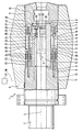
- the barrel weapon 1 has a weapon housing 3 at the rear end of the weapon barrel 2.
- the weapon housing 3 there is coaxial with the core axis 4 the storey 5 in which a sabot projectile 6 ready for firing is inserted.
- the storey 5 is formed by a cylindrical caliber part 7, which with its end faces 8 adjoins insert pieces 10 axially against the caliber part 7 with the interposition of a sealing ring 9.
- the inserts 10 are positively connected to the weapon housing 3 by means of a screw connection 11.
- annular piston 15 is inserted so as to be axially movable.
- the annular piston 15 has a piston head 16 and a piston shaft 17, the transitions from the piston head 16 to the piston shaft 17 on the radially inner and radially outer side having steps 18 and 19, which in corresponding recesses 20 and 21 of seal carriers 22 and 23 in the immerse the rear system.
- the seal carriers 22 and 23 have sealing elements 24 in annular grooves in order in this way to achieve a radial sealing of the cargo spaces 25 and 26 behind the piston head 16.
- Inflow channels 28 and 29 extend from the end face of the annular piston head 16 and open into the charge spaces 25 and 26.
- the openings 30, which are arranged in a ring circumferentially, are each separated from one another by webs 31.
- the openings 30, which are arranged in a circular manner, are each separated from one another by webs 31.
- the openings 30 open out as channels from the combustion chamber in the contact plane 27 in the storey 5 in the rear area.
- an annular body 33 made of an electrically insulating material, for example ceramic, is inserted axially and radially into corresponding recesses in the cylinder wall 32 of the storey 5.
- This annular body represents the plasma torch 33 with the annular electrode 34 inserted in the front area, which is inserted into an annular groove 35 of the plasma torch.
- the electrode 34 is formed from a total of three ring segments which are separate from one another and are each connected to their own electrically insulated supply lines 36 of an energy source 37. The number of segments corresponds to the number of channels 30.
- the position of the individual segments of the ring-shaped electrode 34 is in the area of the openings or of the channels 30 in the caliber part 7.
- the required second electrode 38 is at the rear end of the discharge path (33 ) attached and is in electrical contact with the weapon housing 7.
- the arc is ignited by a thin, electrically conductive layer on the surface of the sabot 39, which at this point is made of an insulating layer or is coated with an insulating layer.
- the arrangement and the amount of the electrically conductive layers in turn correspond to the position and the amount of the individual segments of the first electrode 33.
- a gas pressure is built up in the channels 30 and the combustion chamber area in front of the injection piston 15, which causes the axial injection movement of the piston 15.
- parts of the sabot 39 designed as an insulator can be vaporized by the arc.
- the propellant components 40 and / or the gases generated during the reaction of the propellant components 40 pass through the channels 30 behind the projectile 6 in the storey 5, whereby the projectile is accelerated. While the combustion gases and the partly unreacted propellant components 40 flow past through the plasma torch 33, the arc discharge continues to take place simultaneously via the two electrodes 34 and 38, so that the electrical energy generated thereby is also coupled into the material flowing past. As a result, the flowing matter is brought to a very high speed. With a suitable choice of the blowing agent components 40, combustion products of low molecular weights are also produced. On the basis of known internal ballistic relationships, it follows that the projectile leaves the barrel 2 at a muzzle velocity that is significantly higher than that of conventional weapons.
Landscapes
- Engineering & Computer Science (AREA)
- Physics & Mathematics (AREA)
- Electromagnetism (AREA)
- Plasma & Fusion (AREA)
- General Engineering & Computer Science (AREA)
- Plasma Technology (AREA)
Applications Claiming Priority (2)
| Application Number | Priority Date | Filing Date | Title |
|---|---|---|---|
| DE3820492 | 1988-06-16 | ||
| DE3820492A DE3820492A1 (de) | 1988-06-16 | 1988-06-16 | Rohrwaffe mit chemisch-elektrischem hybridantrieb mittels regenerativer treibmitteleinspritzung |
Publications (2)
| Publication Number | Publication Date |
|---|---|
| EP0346867A2 true EP0346867A2 (fr) | 1989-12-20 |
| EP0346867A3 EP0346867A3 (fr) | 1990-09-19 |
Family
ID=6356666
Family Applications (1)
| Application Number | Title | Priority Date | Filing Date |
|---|---|---|---|
| EP19890110792 Ceased EP0346867A3 (fr) | 1988-06-16 | 1989-06-14 | Canon travaillant avec une propulsion chimique-électrique hybride, créée par l'injection régénérative d'une charge propulsive |
Country Status (4)
| Country | Link |
|---|---|
| US (1) | US4930394A (fr) |
| EP (1) | EP0346867A3 (fr) |
| DE (1) | DE3820492A1 (fr) |
| IL (1) | IL90578A0 (fr) |
Cited By (2)
| Publication number | Priority date | Publication date | Assignee | Title |
|---|---|---|---|---|
| FR2672047A1 (fr) * | 1988-09-10 | 1992-07-31 | Diehl Gmbh & Co | Agent propulseur pour arme hybride. |
| EP0774453A1 (fr) | 1995-11-17 | 1997-05-21 | Ajinomoto Co., Inc. | Procédé pour la préparation des dérivés de 3-amino-2-oxo-1-halogénopropane |
Families Citing this family (9)
| Publication number | Priority date | Publication date | Assignee | Title |
|---|---|---|---|---|
| GB2212352B (en) * | 1986-09-02 | 1990-08-15 | Ferranti Plc | Deinterleaving of radiated signals |
| DE4020673A1 (de) * | 1990-06-29 | 1992-01-09 | Rheinmetall Gmbh | Vorrichtung zur kompaktumsetzung von fluessigtreibstoff in kanonen |
| DE4028411A1 (de) * | 1990-09-07 | 1992-03-12 | Diehl Gmbh & Co | Rohrwaffe mit chemisch-elektrischem hybridantrieb mittels regenerativer treibmitteleinspritzung |
| US5171932A (en) * | 1991-09-30 | 1992-12-15 | Olin Corporation | Electrothermal chemical propulsion apparatus and method for propelling a projectile |
| DE4227570C1 (de) * | 1992-05-29 | 1993-09-30 | Ieg Ind Engineering Gmbh | Anordnung zum Austreiben leichtflüchtiger Verunreinigungen an Ort und Stelle |
| US5608179A (en) * | 1994-02-18 | 1997-03-04 | The United States Of America As Represented By The Administration Of The National Aeronautics And Space Administration | Catalytic ignitor for regenerative propellant gun |
| US7096660B2 (en) * | 2002-05-20 | 2006-08-29 | Keady John P | Plasma impulse device |
| DE102020122337A1 (de) * | 2020-08-26 | 2022-03-03 | LabOrbital GmbH | Heißgaserzeugungsvorrichtung mit monergolem ionischen Treibstoff und Niederspannungsanzündung |
| US12203714B2 (en) * | 2022-03-08 | 2025-01-21 | Eddie L Brooks | Electrical velocity enhancement assembly |
Family Cites Families (10)
| Publication number | Priority date | Publication date | Assignee | Title |
|---|---|---|---|---|
| US4429612A (en) * | 1979-06-18 | 1984-02-07 | Gt - Devices | Method and apparatus for accelerating a solid mass |
| US4341147A (en) * | 1980-06-16 | 1982-07-27 | General Electric Company | Coaxial dual hollow piston regenerative liquid propellant gun |
| US4376406A (en) * | 1981-03-02 | 1983-03-15 | The United States Of America As Represented By The Secretary Of The Navy | Hybrid gun system |
| US4523508A (en) * | 1983-11-02 | 1985-06-18 | General Electric Company | In-line annular piston fixed bolt regenerative liquid propellant gun |
| US4586422A (en) * | 1984-04-10 | 1986-05-06 | General Electric Company | In-line annular piston fixed bolt regenerative variable charge liquid propellant gun with variable hydraulic control of piston |
| US4640180A (en) * | 1985-06-20 | 1987-02-03 | The United States Of America As Represented By The Secretary Of The Navy | Gun-firing system |
| US4706542A (en) * | 1985-08-05 | 1987-11-17 | The United States Of America As Represented By The United States Department Of Energy | Low voltage arc formation in railguns |
| US4664631A (en) * | 1985-10-31 | 1987-05-12 | Loral Electro-Optical Systems, Inc. | Surrogate weapon for weapons effects signatures |
| DE3613260A1 (de) * | 1986-04-19 | 1987-10-29 | Rheinmetall Gmbh | Vorrichtung zur beschleunigung von projektilen durch ein elektrisch aufgeheiztes plasma |
| US4693165A (en) * | 1986-06-27 | 1987-09-15 | General Electric Company | Liquid propellant gun |
-
1988
- 1988-06-16 DE DE3820492A patent/DE3820492A1/de active Granted
-
1989
- 1989-06-02 US US07/360,004 patent/US4930394A/en not_active Expired - Fee Related
- 1989-06-12 IL IL90578A patent/IL90578A0/xx unknown
- 1989-06-14 EP EP19890110792 patent/EP0346867A3/fr not_active Ceased
Cited By (2)
| Publication number | Priority date | Publication date | Assignee | Title |
|---|---|---|---|---|
| FR2672047A1 (fr) * | 1988-09-10 | 1992-07-31 | Diehl Gmbh & Co | Agent propulseur pour arme hybride. |
| EP0774453A1 (fr) | 1995-11-17 | 1997-05-21 | Ajinomoto Co., Inc. | Procédé pour la préparation des dérivés de 3-amino-2-oxo-1-halogénopropane |
Also Published As
| Publication number | Publication date |
|---|---|
| DE3820492A1 (de) | 1989-12-28 |
| DE3820492C2 (fr) | 1990-04-12 |
| IL90578A0 (en) | 1990-01-18 |
| US4930394A (en) | 1990-06-05 |
| EP0346867A3 (fr) | 1990-09-19 |
Similar Documents
| Publication | Publication Date | Title |
|---|---|---|
| DE68909659T2 (de) | Plasma-Waffe mit einem Verbrennungsverstärker. | |
| DE3820492C2 (fr) | ||
| DE3325868C2 (fr) | ||
| DE3344636A1 (de) | Geschossbeschleunigungseinrichtung | |
| DE10020020A1 (de) | Patrone | |
| DE69502041T2 (de) | Mit einer Hülse versehene teleskopische Patrone die kein Leitrohr hat | |
| DE68916770T2 (de) | Mit flüssigen Treibladungen arbeitendes Geschütz zum Abschiessen von Geschossen mit unterschiedlichen Massen und Geschwindigkeiten. | |
| DE2246854C2 (de) | Feuerwaffe, insbesondere kurzbauende Handfeuerwaffe | |
| DE3234638C1 (de) | Abdichtung fuer Differenzdruckkolben-Brennkammersysteme von Rohrwaffen | |
| DE69008208T2 (de) | Mit einer Kombination von Plasmaantrieb und chemischer Treibladung arbeitendes Geschütz. | |
| DE3814332C2 (de) | Vorrichtung zur Beschleunigung von Projektilen | |
| DE4337964C2 (de) | Elektrischer Hybridbeschleuniger für eine Spezialmuntion | |
| DE3716078A1 (de) | Lauf zur beschleunigung von geschossen | |
| DE3432650C2 (de) | Unterkalibriertes Projektil vom Pfeiltyp | |
| DE3816663C2 (fr) | ||
| DE3307730C2 (de) | Rohrwaffe | |
| DE1817694A1 (de) | Automatische Feuerwaffe | |
| DE4028411A1 (de) | Rohrwaffe mit chemisch-elektrischem hybridantrieb mittels regenerativer treibmitteleinspritzung | |
| DE3921400C2 (de) | Kanonenanordnung | |
| DE3836721C2 (fr) | ||
| DE3720297C1 (en) | Differential piston for weapons - uses ring piston coaxial to barrel and enclosing valve member | |
| DE4128575A1 (de) | Geschuetz mit einem geschossantrieb fuer hochgeschwindigkeitsgeschosse | |
| DE4142169A1 (de) | Zuendvorrichtung zum zuenden eines bei seiner verbrennung gase freisetzenden ladungsmaterials, insbesondere zum zuenden der projektil-treibladung einer waffe | |
| DE10335890A1 (de) | Plasmagenerator | |
| DE2366037C2 (de) | Vorrichtung zum gasdichten Abschließen einer Trennfuge |
Legal Events
| Date | Code | Title | Description |
|---|---|---|---|
| PUAI | Public reference made under article 153(3) epc to a published international application that has entered the european phase |
Free format text: ORIGINAL CODE: 0009012 |
|
| AK | Designated contracting states |
Kind code of ref document: A2 Designated state(s): DE FR GB IT NL |
|
| PUAL | Search report despatched |
Free format text: ORIGINAL CODE: 0009013 |
|
| AK | Designated contracting states |
Kind code of ref document: A3 Designated state(s): DE FR GB IT NL |
|
| 17P | Request for examination filed |
Effective date: 19900809 |
|
| 17Q | First examination report despatched |
Effective date: 19920109 |
|
| STAA | Information on the status of an ep patent application or granted ep patent |
Free format text: STATUS: THE APPLICATION HAS BEEN REFUSED |
|
| 18R | Application refused |
Effective date: 19930726 |