EP0346839B1 - Lernverfahren und -system für Roboter - Google Patents
Lernverfahren und -system für Roboter Download PDFInfo
- Publication number
- EP0346839B1 EP0346839B1 EP89110704A EP89110704A EP0346839B1 EP 0346839 B1 EP0346839 B1 EP 0346839B1 EP 89110704 A EP89110704 A EP 89110704A EP 89110704 A EP89110704 A EP 89110704A EP 0346839 B1 EP0346839 B1 EP 0346839B1
- Authority
- EP
- European Patent Office
- Prior art keywords
- robot
- data sets
- vehicle
- data
- robots
- Prior art date
- Legal status (The legal status is an assumption and is not a legal conclusion. Google has not performed a legal analysis and makes no representation as to the accuracy of the status listed.)
- Expired - Lifetime
Links
Images


Classifications
-
- G—PHYSICS
- G05—CONTROLLING; REGULATING
- G05B—CONTROL OR REGULATING SYSTEMS IN GENERAL; FUNCTIONAL ELEMENTS OF SUCH SYSTEMS; MONITORING OR TESTING ARRANGEMENTS FOR SUCH SYSTEMS OR ELEMENTS
- G05B19/00—Program-control systems
- G05B19/02—Program-control systems electric
- G05B19/42—Recording and playback systems, i.e. in which the program is recorded from a cycle of operations, e.g. the cycle of operations being manually controlled, after which this record is played back on the same machine
-
- B—PERFORMING OPERATIONS; TRANSPORTING
- B25—HAND TOOLS; PORTABLE POWER-DRIVEN TOOLS; MANIPULATORS
- B25J—MANIPULATORS; CHAMBERS PROVIDED WITH MANIPULATION DEVICES
- B25J9/00—Program-controlled manipulators
- B25J9/16—Program controls
- B25J9/1656—Program controls characterised by programming, planning systems for manipulators
- B25J9/1664—Program controls characterised by programming, planning systems for manipulators characterised by motion, path, trajectory planning
- B25J9/1666—Avoiding collision or forbidden zones
-
- G—PHYSICS
- G05—CONTROLLING; REGULATING
- G05B—CONTROL OR REGULATING SYSTEMS IN GENERAL; FUNCTIONAL ELEMENTS OF SUCH SYSTEMS; MONITORING OR TESTING ARRANGEMENTS FOR SUCH SYSTEMS OR ELEMENTS
- G05B19/00—Program-control systems
- G05B19/02—Program-control systems electric
- G05B19/418—Total factory control, i.e. centrally controlling a plurality of machines, e.g. direct or distributed numerical control [DNC], flexible manufacturing systems [FMS], integrated manufacturing systems [IMS] or computer integrated manufacturing [CIM]
- G05B19/41815—Total factory control, i.e. centrally controlling a plurality of machines, e.g. direct or distributed numerical control [DNC], flexible manufacturing systems [FMS], integrated manufacturing systems [IMS] or computer integrated manufacturing [CIM] characterised by the cooperation between machine tools, manipulators and conveyor or other workpiece supply system, workcell
-
- G—PHYSICS
- G05—CONTROLLING; REGULATING
- G05B—CONTROL OR REGULATING SYSTEMS IN GENERAL; FUNCTIONAL ELEMENTS OF SUCH SYSTEMS; MONITORING OR TESTING ARRANGEMENTS FOR SUCH SYSTEMS OR ELEMENTS
- G05B2219/00—Program-control systems
- G05B2219/30—Nc systems
- G05B2219/32—Operator till task planning
- G05B2219/32151—Prepare teach data by selecting data from two tables as function of type of work
-
- G—PHYSICS
- G05—CONTROLLING; REGULATING
- G05B—CONTROL OR REGULATING SYSTEMS IN GENERAL; FUNCTIONAL ELEMENTS OF SUCH SYSTEMS; MONITORING OR TESTING ARRANGEMENTS FOR SUCH SYSTEMS OR ELEMENTS
- G05B2219/00—Program-control systems
- G05B2219/30—Nc systems
- G05B2219/40—Robotics, robotics mapping to robotics vision
- G05B2219/40479—Use graphic display, layout of robot path, obstacles to indicate interference
-
- G—PHYSICS
- G05—CONTROLLING; REGULATING
- G05B—CONTROL OR REGULATING SYSTEMS IN GENERAL; FUNCTIONAL ELEMENTS OF SUCH SYSTEMS; MONITORING OR TESTING ARRANGEMENTS FOR SUCH SYSTEMS OR ELEMENTS
- G05B2219/00—Program-control systems
- G05B2219/30—Nc systems
- G05B2219/45—Nc applications
- G05B2219/45083—Manipulators, robot
-
- Y—GENERAL TAGGING OF NEW TECHNOLOGICAL DEVELOPMENTS; GENERAL TAGGING OF CROSS-SECTIONAL TECHNOLOGIES SPANNING OVER SEVERAL SECTIONS OF THE IPC; TECHNICAL SUBJECTS COVERED BY FORMER USPC CROSS-REFERENCE ART COLLECTIONS [XRACs] AND DIGESTS
- Y02—TECHNOLOGIES OR APPLICATIONS FOR MITIGATION OR ADAPTATION AGAINST CLIMATE CHANGE
- Y02P—CLIMATE CHANGE MITIGATION TECHNOLOGIES IN THE PRODUCTION OR PROCESSING OF GOODS
- Y02P90/00—Enabling technologies with a potential contribution to greenhouse gas [GHG] emissions mitigation
- Y02P90/02—Total factory control, e.g. smart factories, flexible manufacturing systems [FMS] or integrated manufacturing systems [IMS]
Definitions
- the present invention relates to a system and method as indicated in the precharacterizing parts of claims 1 and 9.
- Such a prior art system uses third and fourth storage means for storing working commands and basic working patterns, respectively. Repetitive working cycles are conducted which are similar but different in their working contents defined by the first and second data sets.
- JP-A-62-110581 shows a conventional example.
- a robot control system comprises first and second storage means and means for teaching at least one robot.
- the first storage means stores position data sets
- the second storage means stores motion pattern data sets.
- the teaching means selects one of the position data sets and one of the motion pattern data sets in accordance with a type of work, and prepares a teach data to teach motions to the robot by combining the selected position data set and motion pattern data set.
- the robot control system is suitable to an assembly system for assembling automobiles or other vehicles.
- each of the position data sets describing mathematically a position of one robot which may be a working position for spot-welding vehicle body panels, or for positing and holding a body panel, or which may be an original position of the robot.
- the first storage means stores such position data sets of each robot for different kinds and types of vehicles bodies to be assembled.
- Each of the motion pattern data sets is descriptive of a pattern of a path to be traveled by one robot.
- the second storage means stores such pattern data sets for different body types such as a sedan type, hardtop type, a van type and a wagon type.
- the motion pattern data set of each type is usable for vehicle bodies of different kinds as long as the body type is the same.
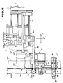
- Fig. 1 is a side view showing a vehicle body main body assembly system of a first embodiment of the present invention.
- Fig. 2 is a sectional view taken across a line II-II of Fig. 1.
- Fig. 3 is a perspective view of a vehicle main body to be assembled in the assembly system of Fig. 1.
- Fig. 4 is a front elevation showing one of robots of the assembly system shown in Fig. 1.
- Fig. 5 is a plan view of a hand portion of the robot shown in Fig. 4.
- Fig. 6 is a side view of the hand portion of the robot shown in Fig. 4.
- Fig. 7 is a view of the hand of the robot of Fig. 4, as viewed in the direction shown by arrows A in Fig. 6.
- Fig. 8 is a schematic view showing a procedure of the first embodiment for preparing a robot teach data.
- Fig. 9 is a schematic view showing the structure of standard motion pattern data used in the first embodiment.
- Figs. 10A, 10B and 10C are views for illustrating paths of hands of robots according to the standard pattern data of the first embodiment.
- Fig. 11 is a flowchart showing a program for conversion process and inversion process according to the first embodiment.
- Fig. 12 is a view showing a vehicle assembly system and a display system according to a second embodiment of the present invention.
- Fig. 13 is a perspective view showing one of assembling robots shown in Fig. 12.
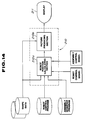
- Fig. 14 is a block diagram showing a graphic processor of the display system according to the second embodiment.
- Fig. 15 is a flowchart showing a process performed by the graphic processor of the second embodiment.
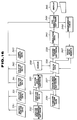
- Fig. 16 is a schematic view showing a robot teaching system according to a third embodiment of the present invention.
- Figs. 17 and 18 are flowcharts showing a main portion of the procedure according to the third embodiment.
- Fig. 19 is a view for illustrating the procedure of the third embodiment.
- Fig. 20 is a schematic view showing a multiaxis control unit employed in the third embodiment.
- Fig. 21-24 are view showing a vehicle body assembly system employed in the third embodiment.
- Fig. 25 is a perspective view for showing a robot-robot interference.
- Fig. 26 is a block diagram showing, as one example, a basic structure of the robot teaching system of the first embodiment.
- Fig. 26 shows a basic arrangement of a robot control system according to a first embodiment of the present invention.
- this system includes at least a first storage means for storing position data sets, a second storage means for storing motion pattern data sets, and a robot teaching means which, in this example, comprises a first selector means for selecting one of said position data sets, a second selector means for selecting one of said motion pattern data sets, and a conversion means for preparing a teach data by using the selected position data set and motion pattern data set.
- the control system further comprises a first discriminating means for producing a first identification signal representing a kind of an incoming work to be assembled, and a second discriminating means for producing a second identification signal representing a type of the incoming work.
- the first selector means is connected with both of the-first and second discriminating means, but the second selector means is connected only with the second discriminating means.
- the first embodiment of the present invention is concretely shown in Figs. 1-11.
- a main body assembly system of this embodiment has a frame structure 2 which has a rectangular section, and surrounds a shuttle bar 1.
- the shuttle bar 1 is used for conveying a work consisting of a plurality of body panels constituting a main vehicle body, to a provisional assembly station in a vehicle body assembly line, and conveying a provisionally assembled main body away from the provisional assembly station.
- the assembly system further has a plurality of robots 3-31 which are, in this embodiment, of a rectangular (orthogonal) coordinate type.
- the robots 3-31 are mounted on the frame structure 2, and distributed, approximately in a manner of bilateral symmetry, in top, bottom, left and right side surfaces of the frame structures 2 which all extend in parallel to the shuttle bar 1.
- Fig. 4 shows the robot 18 as an example.
- the robot 18 is provided in one side of the frame structure 2 as shown in Fig. 2, and used for locating or positioning a side sill portion 101a of a body side panel 101 of a vehicle main body 100 shown in Fig. 3.
- the robot 18 has a base 40, an arm 50, two movable wrist brackets 60 and 61, a base drive mechanism 41, an arm drive mechanism 51, and two bracket drive mechanisms 62.
- the base drive mechanism 51 can cause the base 40 to move relative of the frame structure 2 along a Y direction which is horizontal, and parallel to the longitudinaldirection of the shuttle bar 1.
- the Y direction (or axis) is shown by an arrow Y in Figs.
- the Y direction is perpendicular to the surface of the paper of Fig. 4.
- the arm drive mechanism 51 can move the robot arm 50 relative to the base 40 along an X direction which is horizontal and perpendicular to the Y direction.
- the X direction (or axis) is shown by an arrow X in Fig. 4 and other figures.
- the two bracket drive mechanisms 62 is capable of moving, respectively, the two wrist brackets 60 and 61 relative to the arm 50 in a Z direction (or axis) which is vertical.
- the Z direction is shown by an arrow Z in Fig. 4 and other figures.
- the base drive mechanism 41 moves the base 40 along horizontal rails 42 fixed to the frame structure 2.
- Circulating ball type sliders 43 fixed to the base 40 are in engagement with the rails 42, respectively.
- a ball nut 45 supported on the base 40 is fitted over a ball screw shaft 44 which is fixed to the frame structure 2.
- a servomotor 46 of the base drive mechanism 41 is provided in the base 40, and drivingly connected with the ball nut 45 through a coupling so that the servomotor 46 can rotate the ball nut 45.
- the arm drive mechanism 51 has guide rails 52 fixed to the arm 50, and circulating ball type sliders 53 which are fixed to the base 40 and engaged with the guide rails 52, respectively.
- a ball screw shaft 54 is mounted on the arm 50 between the guide rails 52, and a ball nut 55 is fixed to the base 40.
- the screw shaft 54 is screwed in the ball nut 55, and drivingly connected with a servomotor 56 of the arm drive mechanism 51 through a coupling.
- the servo motor 56 is provided in the arm 50.
- the ball screw shaft 54 is rotated by the servomotor 56.
- Each of the wrist bracket drive mechanism 62 includes two vertically extending guide rails 63 fixed to a forward end of the arm 50, circulating ball type sliders which are fixed to a bracket holder 64, and engaged with the guide rails 63, a ball screw shaft 66 which is supported on the forward end of the arm 50 between the guide rails 63, a ball nut 67 which is fixed to the bracket holder 64 and mounted on the screw rod 66, and a servomotor 68 which is provided in the forward end of the arm 50 and drivingly connected with the ball screw shaft 66 through a coupling so that the servomotor 68 can rotate the ball screw shaft 66.
- the base drive mechanism 41 can move the robot base 40 in the longitudinal Y direction
- the arm drive mechanism 51 can move the arm 50 in the lateral X direction
- the first bracket drive mechanism 62 can move the first wrist bracket 60 in the vertical Z direction
- the second bracket drive mechanism 62 can move the second bracket 61 in the vertical Z direction.
- the first wrist bracket 60 carries a lower positioning tool 70 and a lower welding gun 80
- the second wrist bracket 61 carries an upper positioning tool 90 and an upper welding gun 93, as shown in Figs. 5, 6 and 7.
- each wrist bracke of this example has two hands.
- the lower positioning tool 70 is a device for positioning a lower portion of the side sill 102a of a main floor panel 102.
- the lower welding gun 80 is used for joining the lower portions of the side sills 101a and 102a by spot-welding.
- the lower positioning tool 70 has a gauge holder 71 fixed to the movable wrist bracket 60, a servomotor 72 attached to the gauge holder 71, a gauge drive arm 73 connected with an output shaft 72a of the servomotor 72, and gauge plates 74 and 75.
- the gauge plates 74 and 75 are pivotally connected with the gauge drive arm 73 and the gauge holder 71, respectively, and both gauge plates are connected together to form a parallel link.
- This positioning tool 70 can vary an angle of a gauge surface 75a of the gauge plate 75 from the horizontal while holding a gauge surface 74a of the guage plate 74 vertical, by rotating the gauge drive arm 73 with the servomotor 72. Therefore, this positioning tool 70 can position the lower end of each of different side sills of various shapes.
- the lower spot-welding gun 80 has electrode tips 85 and 87.
- An air cylinder 83 is supported on a bracket 81 fixed to the gauge plate 74, through an equalizer mechanism 82 permitting movement along the X direction.
- the electrode tip 85 is attached to a main body of the air cylinder 83 through an arm 84, and the electrode tip 87 is attached to a piston rod 83a of the air cylinder 83 through an arm 86. Both electrode tips 85 and 87 confront each other.
- the arms 84 and 86 are connected with a welding transformer by feeder cables.
- the electrode tip 87 advances toward the opposite electrode tip 85 until the electrode tip 87 bumps against the workpiece. Then, the main body of the air cylinder 83 is moved backwardly by the action of the equalizer mechanism 82. Therefore, the electrode tips 85 and 87 clamp downwardly projecting flanges of the side sill portions 101a and 102 held at the predetermined position by the locator 70 and others, and then spot-weld the lower portions of the side sills 101a and 102a.
- the upper positioning tool 90 carried by the second movable wrist bracket 61 serves as a device for positioning an upper portion of the side sill 101a of the side panel 101 with respect to the upper portion of the side sill 102a of the main floor panel 102.
- the upper welding gun 93 carried by the second bracket 61 is used for spot-welding the upper portions of the side sills 101a and 102a.
- the upper positioning tool 90 has a gauge plate 92 which can be moved along the X direction with respect to the gauge plates 74 and 75 of the lower positioning tool 70 by a drive mechanism similar to the bracket drive mechanism 70. (In this drive mechanism, however, a servomotor is drivingly connected to a ball screw shaft by a belt drive.) Therefore, this positioning tool 90 can be used for side sills of various shapes.
- a gauge surface 92a of the gauge plate 92 is moved along the X axis to a correct position according to a predetermined side sill shape.
- the upper spot-welding gun 93 is sabstantially identical in construction to the lower welding gun 80.
- the upper welding gun 93 has electrode tips 94 and 95 which can clamp the upper flanges of the side sills 101a and 102a positioned by the upper locator 90 and others, and spot-weld the upper flanges of the side sill portions 101a and 102a.
- Each robot provided on the top and left and right sides of the frame structure 2 has at least one of various hands.
- the hand may be a positioning tool similar to the positioning tool 70 or 90 of the robot 18, or may be a positioning tool which is adaptable to various workpieces by selectively placing one of gauge plates of different kinds, or may be a spot-welding gun which is similar to the welding gun 80, or of some other conventional type.
- Each robot provided in the bottom of the frame structure 2 has at least one hand which may be a locate pin having a latch mechanism or may be a welding gun. In each robot, the hand is mounted on a movable wrist bracket at the forward end of the robot arm.
- a robot teaching system (or method) of this embodiment is arranged to make a computer 110 for CAD (shown in Fig. 8) prepare teach data for each robot, and teach the teach data directly to a control unit 120 of the main body assembly system.
- the teach data of each robot is data for causing the robot to provisionally assemble a vehicle main body in cooperation with the other robots, without interfering with any of the other robots.
- standard motion pattern data 111 is preliminarily inputted into the CAD computer 110 used for vehicle body design.
- the standard motion pattern data 111 consists of two or more parts each of which is prepared uniquely for one of different vehicle body types, and each of which is common to different vehicle kinds (or makes) of vehicles to be assembled in this assembly system.
- the vehicle body types are sedan type, hardtop type and van/wagon type, and there are a sedan type standard motion pattern data, a hardtop type standard motion pattern data, and a van/wagon type standard motion pattern data, as shown in Fig. 8.
- Vehicle of each kind are usually identified by the same name given by the maker, and each vehicle kind includes one or more body types.
- each of the three parts of the standard motion pattern data 111 includes a plurality of motion pattern data sets each of which consists of sequence data 121 and step data 122, and is prepared for a unique one of the robots.
- These motion pattern data sets for each vehicle body type are assigned to the robots so that each set corresponds to a unique one of the robots.
- the sequence data of each set includes a plurality of blocks which are prepared, respectively, for basic operations required for the provisional main body assembly.
- the step data 122 is data for performing these basic operations.
- Each block of the sequence data 121 for a unique one of the basic operations includes a description of motion sequence indicating robot motion pattern and interlock between robots or between a robot and another device (such as the control unit of the assembly line for controlling the shuttle conveyor 1), and a description of numbers of corresponding steps of the step data (, for example, from No. i to No. j) corresponding to the motion sequence.
- the step data 122 includes a plurality of steps, each of which includes descriptions of operating speed of the robot, motion pattern of each movable axis (for example, the base drive mechanism 41, arm drive mechanism 51, bracket drive mechanisms 62 and positioning device 70), data for the motion pattern of each axis, and step interface (I/O) for interlock and actuation of drive means, such as the air cylinder, other than the servomotors.
- steps each of which includes descriptions of operating speed of the robot, motion pattern of each movable axis (for example, the base drive mechanism 41, arm drive mechanism 51, bracket drive mechanisms 62 and positioning device 70), data for the motion pattern of each axis, and step interface (I/O) for interlock and actuation of drive means, such as the air cylinder, other than the servomotors.
- the robots wait for a signal from the control unit of the assembly line indicating a start of forward movement of the shuttle conveyor, and a start signal fo the assembly system. Thereafter, the robots on the bottom of the frame structure 2 put the locate pins at respective waiting positions, and the robots on top and both sides put the positioning tools at respective waiting positions. Furthermore, in the positioning tools, gauge plates of proper shapes are selected according to the vehicle kind of the main body to be assembled.
- the robot motion patterns are as follows: In each bottom robot provided on the bottom of the frame structure 2, for example, the locate pin is moved from the original position to the locating position along the X and Y directions (in the horizontal plane), but held at the original position along the Z axis. (That is, the locate pin is moved only in the horizontal plane without being moved vertically.)
- the lateral robot 18 for positioning the side sill portion 101a and the lateral robot for positioning a rear fender portion 101b (shown in Fig. 3) of the body side panel 101 for example, each positioning device is moved from the original position to the locating position via a predetermined path along the Y and Z directions (in the vertical plane), but held at the original position along the X direction.
- the movable axis motion pattern of each step data is designed to cause these movements.
- the original position of each robot is fixed, and held unchanged irrespective of change in vehicle kind and type.
- the robots waits until the assembly line control unit delivers a signal indicating an arrival of the shuttle conveyor at a predetermined forward limit position. Then, the bottom robots provided in the bottom of the frame structure 2 are caused to put their positioning devices at their respective approach positions at which the devices are ready for positioning.
- the main floor panel 102, body side panels 101 and other workpieces are preliminarily assembled in a rough and temporary manner at a preceding station, and then brought to this provisional assembly station in such a state that the robots can assemble the workpieces into the vehicle main body 100 by moving each workpiece only slightly, and welding the workpieces.
- each locate pin is moved upwardly along the Z direction from its waiting position to its approach position as shown by an arrow A1 in Fig. 10A.
- This approach position is just below the locating position, and at a predetermined distance "a" apart from the locating position.
- the locate pin does not yet reach a corresponding locate hole 102a formed in the main floor panel 102.
- each positioning device is moved laterally along the X direction from its waiting position to its approach position, as shown by arrow B1 in Fig. 10B. This approach position is at a predetermined distance "b" apart from the locating position along the X direction.
- the positioning device In the lateral robot on one side of the frame structure, for positioning the rear fender portion 101b, the positioning device is moved laterally from its waiting position to its approach position, as shown by an arrow C1 in Fig. 10C.
- This approach position is at a predetermined distance "c" downwardly along the Z axis, and at a predetermined distance "d” laterally along the X direction apart from the locating position, as shown in Fig. 10C.
- the movable axis motion patterns of each step are designed to cause these movements, and the axis motion pattern data indicates the predetermined distances a,b,c.
- the third basic operation of the first positioning is as follows: In the bottom robots, each locate pin is moved upwardly to the locating position, and inserted into the locate hole 102a of the main floor panel 102. Therefore, the main floor panel 102 is lifted up from the shuttle conveyor 1, and positioned at a predetermined correct position. Furthermore, the main floor panel 102 is firmly clamped at the predetermined correct position by the before-mentioned latch mechanisms. As to the lateral robots on each side, only the robot for positioning the rear fender portion 101 is moved, and the other robots remain at rest. In the robot for positioning the rear fender portion 101, the positioning tool is moved upwardly with the upward movement of the main floor panel 102. Then, a signal to return the shuttle conveyor is delivered to the assembly line control unit.
- each locate pin is moved upwardly through the distance "a” from the approach position to the locating positionn, as shown by arrow A2 in Fig. 10A.
- the positioning tool is moved upwardly along the Z direction from the approach position to a lift-up position through the distance "c", as shown by an arrow C2 in Fig. 10C.
- the interlock is arranged to cause the locate pins to lift up various portions of the main floor panel 102 simultaneously in unison and cause the rear fender portions 101b on the left and right sides to be lifted up simultaneously with each other and with the upward movement of the main floor panel 102 by synchronizing all the robots for moving the locate pins, and the robots for moving the positioning tools. Furthermore, the shuttle conveyor return signal is generated.
- the axis motion patterns of each step data are arranged to cause these movements, and the axis motion pattern data indicates the distances a, c.
- the step I/O data is designed to synchronize the robots, and to actuate the latch mechanisms.
- the fourth basic operation of second position is as follows: The robots wait until the main floor panel 102 reaches an upper limit position. Thereafter, in the lateral robots for positioning the body side panel 101 on each side, the positioning tools are moved toward the center line of the vehicle body as far as the respective locating positions. Therefore, the left and right side panels 101 are correctly positioned on both sides of the main floor panel. Then, the side panels 101 are firmly clamped by clamp mechanism which are provided in the positioning tools and actuated by air cylinders. In the topside robots located on the top of the frame structure 2, their positioning tools are placed on respective approach positions, and held ready for moving to the locating positions.
- the robot motion patterns in this basic operation are as follows:
- each positioning tool is moved laterally along the X direction from the approach position to the locating position through the distance "b", as shown by an arrow B2 in Fig. 10B. Therefore, the side sill portion 101a on each side is pushed toward the center of the vehicle body, and positioned correctly.
- each positioning tool is moved laterally along the X direction from the lift-up position to the locating position through the distance "d", as shown by an arrow C3 in Fig. 10C. Therefore, the rear fender portion 101b on each side is pushed against the main floor panel 102, and held at the correct position.
- the interlock is designed to synchronize all the robots for moving the positioning tools so that the robots can push and position various portions of the each side panel 101 simultaneously.
- the axis motion patterns of each step data is arranged to cause these movements, the axis motion pattern data is arranged to indicates the distances "b" and "d”, and the step I/O data is arranged to cause waiting for the termination of movements of the bottom robots, synchronization of the robots, and actuation of the clamp mechanisms.
- each positioning tool of the topside robots provided on the top of the frame structure 2 is moved from its approach position to its locating position. Therefore, roof rails, air box, shelf panel, rear panel and other workpieces lying between the left and right body side panels 101 are positioned, and held at correct positions. Then, a weld start signal is produced to start the welding operation.
- the robots having only the welding gun and the robots having both the welding gun and the positioning tool are caused to spot-weld the workpieces which are positioned and firmly held as the result of the first, second and third positioning operations.
- the workpieces are provisionally assembled into the main body 100.
- each of the lower and upper welding guns 80 and 93 is moved away from its first weld position W1 or W3 along the vertical Z direction through a predetermined distance "e", as shown by an arrow B3 in Fig. 6, then moved longitudinally along the Y direction as shown by an arrow B4 and finally moved vertically along the Z direction to a second weld position W2 or W4 through a predetermined distance "f", as shown by an arrow B5.
- the axis motion pattern data of the step data is arranged to indicate the distances "e" and "f".
- each positioning tool of the top and lateral robots is returned to its approach position by the path in the reverse direction.
- each locate pin of the bottom robots is returned to the original position via the approach position, and each positioning tool of the topside and lateral robots is returned to its original position. Therefore, the provisionally assembled vehicle main body 100 is placed on the shuttle conveyor 1. Thereafter, a signal is sent to the assembly line control unit to command a forward movement of the shuttle conveyor 1.
- the robot control system can automatically determine proper travel paths by being provided with only the data about the position coordinates of the original positions, locating positions, welding positions and other positions. These paths can be made to have a common pattern among the vehicles which are of the same type, and have approximately identical vehicle body constructions.
- the path of the positioning tool for positioning the rear upper portion of each body side panel for the sedan type shown in Fig. 3 is different from that for the van/wagon type.
- the positioning of the rear upper portion of the side panel is performed by applying a gauge portion to the upper portion of the rear pillar and the upper end of the trunk opening, from above. Therefore, the pattern for the sedan type is such that the positioning tool is first moved laterally to a position above the locating position, and then moved downwardly to the locating position.
- the positioning is performed by applying the gauge portion from below to the upper portion of a frame of a rear side window.
- each robot motion pattern is the form of a path of a predetermined point of the robot which is described by a continuous line consisting of line segments connected end to end.
- the line segments are straight, and connected at right angles or in alignment.
- the CAD computer 110 having the thus-arranged standard motion pattern data is notified of the kind and type of a vehicle to be assembled, and then prepares the teach data in the following process.
- the CAD computer 110 selectively takes out, from CAD data 112, information on the locating and welding positions, and cross sectional shapes at the locating positions, of a vehicle body of the specified kind and type. These positions and cross sectional shapes are preliminarily determined at the time of vehicle body design by the CAD computer 110, and stored in the CAD data 112.
- the storage device for CAD data 112 stores the locating and welding positions and cross sectional shapes of all the vehicle kinds and all the vehicle types employed in this assembly line.
- the CAD computer 110 performs a process 113 for determining locating and welding positions by using these locating and welding positions in the vehicle body, taken out from the CAD data 112, and by so doing produces locating and welding position data 114 indicating the locating and welding positions in the coordinate system of the main body assembly system.
- the CAD computer 110 produces teach data 116 by performing a conversion process 115 by the use of the thus-obtained locating and welding position data 114, data on the predetermined original positions of the robots, and the standard motion pattern data 111 of the specified vehicle type.
- Fig. 11 is a flowchart for showing the conversion process 115, and a reverse process 118 for modifying the standard motion pattern 111. Steps 172-180 correspond to the conversion process 115, and steps 181-191 correspond to the reverse process 118.
- the computer 110 proceeds from a step 171 to the step 172.
- the computer 110 reads the locating and welding position data 114, the above-mentioned original position data of the robots, and the standard motion pattern data 111 of the selected vehicle type.
- the computer 110 copies the sequence data 121 (shown in Fig. 9) of a predetermined one of the robots, and modifies, if necessary, the contents of the interlock of the sequence data 121 in accordance with the specified vehicle kind by using predetermined conditions.
- the computer 110 copies the operating speed of a predetermined part of the step data 122 at the step 176, and calculates the distance of each movement of each movable axis at the step 178 by using the above-mentioned locating and welding position data, original position data, axis motion pattern, and axis motion pattern data.
- the computer 110 copies the step I/O data, and modifies, if necessary, the step I/O data in conformity with the specified vehicle kind by using predetermined conditions.
- the steps 177 and 178 are repeated until it is determined at the step 177 that the operation of the step 178 is completed for all the axes.
- the steps 175-179 are repeated until it is determined at the step 175 that the operations of the steps 175-179 are performed for all the step data.
- the teach data for the predetermined robot is completed when the operations of the steps 175-179 are completed for all the step data. Therefore, if the steps 175-179 are repeated for all the step data, then the computer 110 returns from the step 175 to the step 173 to produce the teach data of the next robot.
- the computer 110 proceeds from the step 173 to a step 180 to register the teach data.
- the thus-prepared teach data 116 is transferred from the CAD computer 110 to the assembly line control unit 120 as shown in Fig. 8 after an examination to confirm the immunity from interference and other defects, with a display of the CAD computer 110 by which operating conditions are shown by a simulation based on the teach data.
- the teach system of this embodiment employs the reverse conversion process 118, as shown by broken lines in Fig. 8.
- the reverse process is designed to correct faulty portions of the teach data to produce modified teach data 117 on the basis of the results of the above-mentioned simulation or the results of an actual experimental operation of the main body assembly system.
- the modified teach data 117 is used by the assembly line control unit 120 for actual production of vehicle bodies.
- the reverse conversion process 118 of this embodiment is designed to modify the standard motion pattern data 111 by producing a modified standard pattern data and comparing the original standard motion pattern data 111 with the modified pattern data.
- the CAD computer 110 first proceeds from the step 171 to the step 181.
- the computer 110 reads the locating and welding position data 114, the above-mentioned original position data, the standard motion pattern data 11 and the original and modified versions 116 and 117 of the teach data.
- the computer 110 determines whether the motion sequence of each basic operation is equal between the original and modified versions 116 and 117 of the teach data. If it is not equal, the computer 110 modifies the motion sequence of the standard motion pattern data in conformity with the motion sequence of the modified version.
- the computer 110 determines the step numbers corresponding to each motion sequence are equal between the original and modified versions 116 and 117.
- the computer 110 changes the step numbers of the standard motion pattern data in conformity with the numbers of the modified version 117.
- the computer 110 determines whether there is any additional step in the modified version 117.
- the computer 110 determines whether each step data is equal between the original and modified versions 116 and 117. If there is some additional step or some step data is not equal, the computer 110 proceeds to the step 190.
- the computer 110 calculates data of a new travel path by using the modified teach data 117, and modifies the standard motion pattern data by modification or addition of step data in accordance with the result of the calculation. Furthermore, the computer 110 copies the altered or added step I/O data and operating speed of the modified version to the altered or added step data.
- the computer 110 determined whether check of all the step data is completed or not.
- the modification of the standard motion pattern data of the specified robot is completed when the step 181-190 are repeated for all the steps of the step data. Therefore, the computer 110 returns from the step 187 to the step 182 to repeat the steps 182-190 for the next robot.
- the steps 182-190 are repeated until the motion pattern data is modified for all the robots. Then, the computer 110 proceeds from the step 182 to the step 191 to register the standard motion pattern data (replace the original version of the standard motion pattern data by the modified version).
- the locating and welding positions in the vehicle body are preliminarily determined at the time of the vehicle body design by CAD.
- the teach system of this embodiment can cause the CAD computer to automatically produce the proper teach data of each robot by only specifying the vehicle kind and type of the vehicle to be assembled, and to transfer the thus-prepared teach data to the assembly line control unit. Therefore, the teach system of the embodiment can significantly reduce the time required for preparing the teach data of many robots, and the time for teaching the robots.
- the teach system of the embodiment can modify the standard motion pattern data 111 in accordance with the results of modification of the teach data. Therefore, the propriety of the teach data can be improved more and more by learning process as the preparation of the teach data is repeated.
- the teach system of the illustrated embodiment employs three vehicle body types, it is possible to add one or more other types, or to subdivide any one or more of the vehicle body types. Furthermore, it is possible to employ robots of various other types (for example, articulated robots).
- FIGs. 12-15 A second embodiment of the present invention is shown in Figs. 12-15.
- a vehicle body assembly system 201 is provided at a main body provisional assembly station of an assembly line. Workpieces, such as a main floor panel, left and right body side panels, a roof panel, a rear panel, a cowl top assembly and a shelf panel, are carried together into this provisional assembly station. There, the assembly system 201 positions these workpieces at predetermined relative positions so as to satisfy a predetermined assembly accuracy, and provisionally assembles these workpieces into a vehicle main body 202, like the assembly system of the first embodiment.
- the assembled main body 202 is carried from the provisional assembly station to a next station of the assembly line by a shuttle conveyor 203. At the stations following the provisional assembly station, the vehicle body is completed by additional shots of spot welding and addition of other panels.
- the assembly system 201 has a frame strucure 204, a plurality of robots 205, and an assembly robot control unit 206, like the assembly system of the first embodiment.
- the robots 205 are of an orthogonal type, and mounted on the frame structure 204.
- Each robot 205 has one or more tools at its hand portion.
- the tools of some robots are jigs (positioning tools) which are used for positioning a workpiece.
- a clamp device driven by an air cylinder for holding a workpiece.
- the tools of some robots are welding guns.
- Fig. 13 shows, as an example, the robot 205 which is encircled by a one dot chain line A in Fig. 12.
- This robot 205 is used for positioning a side sill portion of the body side panel.
- This robot 205 has linear motion mechanisms 205a, 205b, and 205c and servomotors 205d, 205e and 205f for driving the linear motion mechanisms, respectively.
- the linear motion mechanisms are of an ordinary type using a ball screw shaft and a ball nut.
- This robot carries a tool 207 which a jig.
- the robot can move the tool 207 along the Y axis which is horizontal and parallel to the longitudinal direction of the shuttle conveyor 203, the X axis which intersects the Y axis at right angles in a horizontal plane, and the vertical Z axis, to a predetermined locating position appropriate for positioning the side sill portion 208.
- Each of the other robots is constructed substantially in the same manner, and is capable of moving at least one tool and jig or the welding gun, along the X, Y and Z directions.
- the jig 207 shown in Fig. 13 has first and second gauge plates 207a and 207b, a linear motion mechanism 207c having a ball screw shaft and a ball nut for moving the gauge plate 207a along the Z axis, a rotary motion mechanism 207d for rotating the gauge plate 207b in a vertical plane, and servomotors 207e and 207f for driving the motion mechanisms 207c and 207d, respectively.
- the robot 205 can vary the space between the first and second gauge plates 207a and 207b, and the angle of the gauge plate 207b, so that this robot is usable for side sills of various shapes. All the other robots are also adaptable to vehicle bodies of various types and various makes.
- the robot control unit 206 has a plurality of robot group control sections 206a and an assembly control section 206b.
- the robots 205 are classified into several groups according to their functions. For example, there are a group of robots for positioning the main floor panel, a group of robots for positioning the body side panels and a group of robots for welding.
- Each of the robot group control sections 206a is designed to control one of the robot groups.
- the assembly control section 206b is designed to control operations of the tools of the robots, to monitor the existence or absence of workpieces and operating conditions of the tools by using sensors provided in the tools, and to control the interlock among the robot group control sections 206a.
- the robot group control sections 206a control each robot according to a group control program for controlling one of the robot groups, and an individual robot control program for controlling one of the robots, which are prepared by using a CAD data about shapes of parts of the vehicle body prepared by a CAD system, data about shapes of parts of each robot, and data about a shape of each tool.
- the assembly control section 206b controls operations of the robot groups according to an assembly control program so designed as to perform operations of an assembly in a sequence corresponding to the structure of the main body 2.
- the workpieces are positioned and held at the predetermined positions relative to one another, and spot-welded together.
- an internal state display system 209 for making visible the internal states of the assembly system 201 while the main body is being actually assembled in the assembly system 201.
- the display system 209 has graphic processor 210 having an ordinary CPU, a display unit 211 having a CRT, a work shape data memory 212, a device shape data memory 213, a robot control program memory 214, and an assembly sequence program memory 215.
- the work shape data memory 212 is a memory section for storing the CAD data describing a three dimensional shape of each vehicle body panel.
- the device shape data memory 213 is a memory section for storing shape data describing three dimensional shapes of various parts of the assembly system 201 such as the frame structure 204, the various portions of each robot 205, the jigs and the welding guns.
- the robot control program memory 214 is a memory section for storing the control programs for controlling the robots, preliminarily taken in from the robot group control sections 206a through an interface 216.
- the assembly sequence program memory 215 is a memory section for storing an assembly sequence program which is preliminarily taken in from the assembly control section 206b through an interface 216, and which is arranged to instruct the interlock of the robot groups, and sequences of operations of the jigs and welding guns.
- the graphic processor 210 has a robot position calculating section 210a and a picture producing section 210b.
- the robot position calculating section 210a reads the content of an operation currently being performed by the robot currently being examined, from the programs stored in the robot control program memory 214 and the assembly sequence program memory 215 in accordance with at least one robot control signal from the robot group control sections 206a and at least one assembly control signal from the assembly control section 206b.
- the robot position calculating section 210a reads the shape data describing the shapes of the various portions of the robot, from the device shape data memory 213. Then, the robot position calculating section 210a calculates current positions of the various portions of the robot by using the shape data and the content of the current operation (i.e.
- the picture producing section 210b produces a graphic model picture image of each of the portions of the robot and the workpiece by using the shape data of the workpiece and the robot portions taken from the work shape data memory 212 and the device shape data memory 213. Then, the picture producing section 210b produces a composite graphic model picture image of the robot by superimposing the graphic model pictures of the various robot portions over one another by placing them at the respective current positions calculated by the calculting section 210a. Furthermore, the picture producing section 210b can superimpose the graphic model picture image of the tool at the forward portion of the robot arm, and the graphic model picture image of the workpiece at the predetermined position over the composite image. Then, the picture producing section 210b delivers picture image data of the finally obtained composite picture image, to the display unit 211.
- the graphic processor 210 performs a procedure shown in Fig. 15 when the graphic processor 210 is instructed, before or during actual operation of the assembly system 201, to show a predetermined one or ones of the robots.
- the graphic processor 210 reads the currently existing robot control signal directed to the designated robot, through the interface 216.
- the graphic processor 210 reads the currently existing assembly control signal associated with the designated robot, through the interface 216.
- the graphic processor 210 calculates the current positions of the portions of the designated robot and workpiece, and produces the composite graphic picture image of the designated robot and its surroundings.
- the graphic processor 210 cause the display unit 221 to exhibit the picture image, as shown in Fig. 12, by sending thereto the picture image data.
- This display system is capable of showing each robot in either one of the two dimentional and three dimentional representations. One of the two dimentional and three dimentional representations is selected according to the need.
- the display system 209 of this embodiment makes it possible to observe the interior portions of the assembly system 201 during actual operation.
- FIG. 16-25 A third embodiment of the present invention is shown in Figs. 16-25.
- Figs. 21-24 show a vehicle body provisional assembly station of this embodiment, similar to those of the preceding embodiments.
- Parts constituting a vehicle body such as a main floor panel, left and right body side panel, a roof panel, and a rear panel are assembled in a temporary manner into a vehicle body B by bending ends of these panels at a preceding station of the assembly line, and then the thus-assembled body B is carried into the provisional assembly station for spot welding by a shuttle bar (or transfer bar) 301.
- a frame structure 303 surrounding the shuttle bar 301 is constructed on a foundation 302.
- a deck 5 is supported above the frame structure 303 by upright posts 304.
- a main controller 306 is installed on the deck 305.
- the deck 305 is provided with one or more ladders 307 for an operator to go up to the upper floor formed by the deck 5, and a safety fence 305a.
- a bottom 303a of the frame structure there are provided a plurality of bottom robots 320 which are locators for positioning and supporting the vehicle body B, as shown in Fig. 23.
- a plurality of assemblying robots 309 are provided in the top and left and right sides of the frame structure 303.
- the frame structure 303 has a plurality of longitudinal guide rails 310 extending along the longitudinal Y axis parallel to the longitudinal direction of the shuttle bar 301.
- the assemblying robots 309 are movable along the guide rails 310.
- the assemblying robots 309 are used for assemblying the vehicle body by positioning, clamping and welding vehicle body panels.
- This vehicle assembly system is arranged to assemble vehicle bodies of different kinds and different types automatically by controlling the robots.
- Fig. 20 shows two of the bottom robots, i.e. the positioning locators 320, by way of example.
- the locating positions are different according to the kind and type of a vehicle body to be assembled. Therefore, each locator 320 moves automatically along the X, Y and Z directions to a locating position adapted to the designated vehicle kind and type.
- the first and second positioning locators 320a and 320b taken as two examples in Fig. 20 are connected, respectively, first and second locator controllers 308a and 308b.
- the main controller 306 is connected with the locator controllers, and arranged to control data transmitted to the positioning locators 320.
- a host computer 312 is connected with the main controller 306 and a data file 311.
- the data file 311 takes the form of a storage device of a large capacity such as a magnetic drum storage or a hard disc storage.
- the data file 311 stores teach data describing paths (loca) and speeds of the robots which are preliminarily determined by a CAD simulation.
- the host computer 312 reads out the teach data from the data file 311, output data regarding start, stop and locating position of each robot, and controls and timings of actions of the robots and other devices.
- Figs. 16-19 show teaching system and method according to the third embodiment of the invention.
- a locator position determining software 332 is arranged to perform calculation to determine a locating position data 333 by using a section position data 330 and a locator position data 331.
- the locating position data 333 is sent to a pattern data conversion software 335 together with a standard pattern data 334 which is information on paths between points of the data 333.
- the pattern data conversion software 335 outputs a teach data 336 by performing a conversion process.
- This teach data 336 is fed back to the standard pattern data 334 by a teach data conversion software 337 for performing a conversion of the teach data 336.
- the teach data 336 is rearranged by an editor 338, and then converted into the form of a simulation data 340 by a graphic engine software.
- the simulation data 340 is sent to a CAD simulation software 344 together with a section display data 341, a locator display data 342 and a panel display data 343.
- the CAD simulation software 344 converts the input data into the form ready for display, and sends output data to a display unit 345 to show the result of the simulation.
- an interference check software 346 checks the result of the simulation to determine whether there exists any interference among the robots and workpieces. If it is judged that some robot interferes with another robot or some workpiece, then a teach data rewrite software 347 takes in the teach data 336 and modifies the teach data 336 so as to eliminate the interference. The modified teach data is sent again to the softwares 339, 344 and 346.
- Fig. 17 and 18 shows mainly the processes of the interference check 346 and the teach data rewrite 347.
- the teaching system of this embodiment first prepares a basic teach data for a manipulator of every robot.
- the basic teach data is data which describes a shortest path traveled by a predetermined portion of the manipulator 321 from the beginning to the end of each operation.
- This basic teach data is converted into a basic simulation data by the graphic engine software 339.
- the teaching system calculates, at a step 381, data representing a space S occupied by the manipulator of each robot.
- the data of the occupied space S is a function of time and changing with time.
- the space is divided into regularly arranged unit spaces (or cells) of the shape of a cube or a rectangular parallelpiped, as shown in Fig. 19.
- the teaching system indicates the unit spaces occupied by the manipulator of each robot, by an occupied space data which is changing with time.
- the teaching system prepares the occupied space data of each robot for all the operations, and stores it in a storage device of a CAD station.
- the control unit of the teach system sets a time register T for measuring time, at zero.
- the teaching control unit proceeds to a step 383 and there reads out the occupied space data of all the manipulators corresponding to an instant specified by the time register content T, that is, an end of the time length T staring from a reference time point.
- the teaching control unit sets a manipulator number of a manipulator number register equal to 1 to select one of the manipulators.
- the teaching control unit proceeds to a step 385.
- the control unit determines whether there exists an interference of the manipulator specified by the manipulator number MN with the other manipulators by checking whether there is any overlap between the occupied space of the designated manipulator and the occupied spaces of the other manipulators.
- the teach system may be arranged to further check interference between the designated manipulator and the workpieces in the same manner.
- step 386 the control unit proceeds to a teach data rewrite subroutine, and returns therefrom to the step 383. If the control unit judges that there is no intereference, then the control is transferred to a step 387 at which the control unit determines whether the manipulator number MN is equal to a final manipulator number MNEND. If MN is not equal to MNEND, then the control unit increases MN by one at the step 388, and returns to the step 385 to check the manipulator of the next number. When MN becomes equal to MNEND, the control unit determines, at a step 389, whether the time register content T becomes equal to a predetermined time length TEND representing a time length required for all the operations.
- control unit increments T at the step 390, and thereafter returns to the step 383. In this way, the control unit searches for interferences among all the manipulators (and the workpieces) from the beginning to the end of the assembly process at this assembly station until T becomes equal to TEND.
- the above-mentioned teach data rewrite subroutine is shown in Fig. 18. If any interference is found and this subroutine is entered, the control unit determines, at a step 391, whether there is any empty cell (unit space) around the manipulator of the number MN. If there is an empty cell or empty cells enough to avoid the interference in the immediate vicinity of the manipulator, then the control unit changes the teach data, at a step 392, so as to move the space occupied by the manipulator of the number MN at that instant, to the closest empty space. In this way, the control unit avoid the interference by modifying the teach data. If there remains no empty space around the manipulator currently under examination, then the control unit proceeds from the step 391 to a step 393.
- the control unit changes the teach data so as to move the space currently occupied by the manipulator of the number MN, to the space which was occupied by this manipulator, a unit time ago, at the previous instant when the time register content was equal to T-1.
- the control unit postpones the movement of the manipulator of the number MN so as to prevent the coincidence in time, and cause the manipulators to occupy the same space asynchronously.
- the control unit returns to the step 383 of the main routine.
- the teach system of the third embodiment can correct the teach data very easily.
Landscapes
- Engineering & Computer Science (AREA)
- Physics & Mathematics (AREA)
- Automation & Control Theory (AREA)
- General Physics & Mathematics (AREA)
- Quality & Reliability (AREA)
- Manufacturing & Machinery (AREA)
- General Engineering & Computer Science (AREA)
- Robotics (AREA)
- Mechanical Engineering (AREA)
- Manipulator (AREA)
- Automatic Assembly (AREA)
- Numerical Control (AREA)
- Automobile Manufacture Line, Endless Track Vehicle, Trailer (AREA)
Claims (10)
- Roboter-Steuersystem mit:
einer Maschinen-Anordnung (2, etc.), die mehrere Roboter (3-31) aufweist;
einer ersten Speichereinrichtung zum Speichern erster Datensätze (114);
einer zweiten Speichereinrichtung zum Speichern zweiter Datensätze (111) und
einer Lerneinrichtung (110) zum Auswählen eines der ersten Datensätze nach Maßgabe eines ersten Signals und eines der zweiten Datensätze nach Maßgabe eines zweiten Signals, die eine Art der Arbeit angeben, zum Bilden eines Lerndatensatzes (116) aus den ausgewählten Datensätzen und zum Lehren mindestens eines der Roboter;
dadurch gekennzeichnet,
daß die Maschinen-Anordnung (2, etc.) zur Montage unterschiedlicher Kraftfahrzeugkarosserien dient, die in Gruppen unterschiedlicher Fahrzeugarten klassifiziert sind, wobei jede Fahrzeugart eine oder mehrere Karosserietypen enthält;
jeder der ersten Datensätze (114) ein Positionsdatensatz ist, der eine Arbeitsposition eines der Roboter beschreibt, und jeder der zweiten Datensätze ein Bewegungsmuster-Datensatz ist, der ein Muster von Bewegungen eines der Roboter beschreibt, und
die Lerneinrichtung (110) einen der ersten Datensätze (114) nach Maßgabe beider, des ersten Signals, das ein erstes Identifizierungssignal zum Unterscheiden der Fahrzeugarten ist, und des zweiten Signals aussucht, das ein zweites Identifizierungssignal zum Unterscheiden der Karosserietypen ist, und die Lerneinrichtung einen der zweiten Datensätze (111) nach Maßgabe des zweiten Identifizierungssignals ohne Beziehung zu dem ersten Identifizierungssignal auswählt. - Roboter-Steuersystem nach Anspruch 1, dadurch gekennzeichnet, daß die Karosserietypen zwei oder mehrere eines Sedantyps, Hardtoptyps und Kombityps sind, jeder der Bewegungsmuster-Datensätze einem einheitlichen einen der Karosserietypen entspricht und den Fahrzeugarten gemeinsam ist, solange der Karosserietyp gleich ist, und
die Positionsdatensätze unterschiedliche Datensätze aufweisen, die jeweils den Fahrzeugarten des gleichen Karosserietyps entsprechen. - Roboter-Steuersystem nach Anspruch 1, dadurch gekennzeichnet, daß die Karosserietypen einen ersten Karosserietyp aufweisen, der ein Sedantyp ist, und einen zweiten Karosserietyp, der zum Sedantyp unterschiedlich ist, die Fahrzeugarten eine erste Fahrzeugart aufweisen, die die ersten und zweiten Karosserietypen enthalten, und eine zweite Fahrzeugart, die die ersten und zweiten Karosserietypen aufweist, die Bewegungsmuster-Datensätze einen ersten Musterdatensatz aufweisen, der dem ersten Karosserietyp entspricht, und einen zweiten Musterdatensatz, der dem zweiten Karosserietyp entspricht, die Positionsdatensätze einen ersten Positionsdatensatz aufweisen, der dem ersten Karosserietyp der ersten Fahrzeugart entspricht, einen zweiten Positionsdatensatz, der dem zweiten Karosserietyp der ersten Fahrzeugart entspricht, einen dritten Positionsdatensatz, der dem ersten Karosserietyp der zweiten Fahrzeugart entspricht, und einen vierten Positionsdatensatz, der dem zweiten Karosserietyp der zweiten Fahrzeugart entspricht, und die Lerneinrichtung (110) den ersten Musterdatensatz und den ersten Positionsdatensatz für den ersten Karosserietyp der ersten Fahrzeugart auswählt, den zweiten Musterdatensatz und den zweiten Positionsdatensatz für den zweiten Karosserietyp der ersten Fahrzeugart, den ersten Musterdatensatz und den dritten Positionsdatensatz für den ersten Karosserietyp der zweiten Fahrzeugart und den zweiten Musterdatensatz sowie den vierten Positionsdatensatz für den zweiten Karosserietyp der zweiten Fahrzeugart auswählt.
- Roboter-Steuersystem nach einem der vorhergehenden Ansprüche, wobei jeder der Bewegungsmuster-Datensätze eine Folge von Roboterbewegungen beschreibt und die Lerneinrichtung die Lerndaten derart bildet, daß einer der Roboter aus einer vorbestimmten ursprünglichen Position in eine ausgewählte eine der Arbeitspositionen durch Folgen der Folge von Roboterbewegungen bewegt wird, die durch den ausgewählten einen der Bewegungsmuster-Datensätze spezifiziert sind.
- Roboter-Steuersystem nach einem der vorangehenden Ansprüche, wobei das System eine erste Unterscheidungseinrichtung zum Erzeugen eines ersten Identifikationssignals und eine zweite Unterscheidungseinrichtung zum Erzeugen des zweiten Identifikationssignals aufweist und die Lerneinrichtung eine erste Auswähleinrichtung aufweist, die mit der ersten und der zweiten Unterscheidungseinrichtung verbunden ist, um einen der Positionsdatensätze auszuwählen, sowie eine mit der zweiten Unterscheidungseinrichtung verbundene zweite Auswähleinrichtung zum Auswählen eines der Musterdatensätze aufweist.
- Roboter-Steuersystem nach einem der vorangehenden Ansprüche, wobei das Roboter-Steuersystem außerdem eine Roboterpositions-Berechnungseinrichtung zum Bestimmen einer Position des Roboters zu einem bestimmten Zeitpunkt, eine Grafikmodell-Generatoreinrichtung zum Erzeugen eines Grafikmodells des Roboters durch Verwendung der Position des Roboters, die von der Roboterpositions-Berechnungseinrichtung bestimmt ist, sowie von Roboter-Formdaten, die die Formen der Teile des Roboters beschreiben, und eine Anzeigeeinrichtung zum Sichtbarmachen der Grafikmodelle des Roboters aufweist.
- Roboter-Steuersystem nach Anspruch 6, wobei die Grafikmodell-Generatoreinrichtung außerdem zusammengesetzte Bilddaten erzeugt, um ein Bild der Arbeit auf ein Bild des Roboters durch Verwendung des Grafikmodells des Roboters und eines Grafikmodells der Arbeit aufzutragen.
- Roboter-Steuersystem nach einem der vorhergehenden Ansprüche, wobei das System außerdem eine dritte Speichereinrichtung zum Speichern einer ersten Sammlung von Daten, die einen ersten besetzten Raum angeben, der ein von einem ersten Roboter besetzter Raum ist und sich mit der Zeit bewegt, und einer zweiten Sammlung von Daten, die einen zweiten besetzten Raum angeben, der der von einem zweiten Roboter besetzte Raum ist, und sich mit der Zeit bewegt, sowie eine Prüfeinrichtung zum Auslesen von Daten aus der dritten Speichereinrichtung, um die ersten und zweiten besetzten Räume zu einem beliebigen Zeitpunkt zu bestimmen, um zu bestimmen, ob die ersten und zweiten Roboter sich gegenseitig stören,durch Verwendung der aus der dritten Speichereinrichtung ausgelesenen Daten, und zum Modifizieren eines Inhaltes der dritten Speichereinrichtung, wenn festgestellt wird, daß eine Störung auftritt.
- Roboter-Steuerverfahren mit:
einem ersten Schritt zum Auswählen eines von ersten Datensätzen (114) nach Maßgabe eines ersten Signals und eines von zweiten Datensätzen (111) nach Maßgabe eines zweiten Signals;
einem zweiten Schritt zum Bilden eines Lerndatensatzes (116), um einem Roboter Bewegungen zu lehren durch Zusammenfassen der ausgewählten Datensätze und zum Lehren des Roboters mit dem Lerndatensatz;
dadurch gekennzeichnet, daß
die ersten und zweiten Datensätze (114, 111) zum Montieren unterschiedlicher Fahrzeugkarosserien unterschiedlicher Kategorien dienen, die in unterschiedliche Fahrzeugarten klassifiziert sind und außerdem in unterschiedliche Karosserietypen klassifiziert sind;
jeder der ersten Datensätze (114) ein Positionsdatensatz ist, der eine Arbeitsposition eines der Roboter beschreibt, und jeder der zweiten Datensätze ein Bewegungsmuster-Datensatz ist, der ein Bewegungsmuster eines der Roboter beschreibt, und
der erste Schritt durch Auswählen eines der ersten Datensätze (114) nach Maßgabe beider, des ersten Signals, das ein erstes Identifikationssignal ist, das die Fahrzeugarten unterscheidet, und des zweiten Signals, das ein zweites Identifizierungssignal ist, das die Karosserietypen unterscheidet, und durch Auswählen eines der zweiten Datensätze (111) nach Maßgabe des zweiten Identifizierungssignals ohne Beziehung zu dem ersten Identifizierungssignal ausgeführt wird. - Roboter-Steuerverfahren nach Anspruch 9, wobei die Roboter-Positionsdatensätze Datensätze sind, die unterschiedliche Positionen des Roboters jeweils beschreiben und zur Montage von Fahrzeugkarosserien unterschiedlicher Fahrzeugarten und unterschiedlicher Karosserietypen verwendet werden, und die Roboter-Bewegungsmuster-Datensätze Datensätze sind, die Bewegungsmuster der Roboter beschreiben, die jeweils für diese unterschiedlichen Typen benutzt werden, und wobei der erste Schritt durch Auswählen eines der Positionsdatensätze nach Maßgabe eines ersten Fahrzeug-Identifizierungssignals, das die Art eines Fahrzeuges bezeichnet, das zu montieren ist, und eines zweiten Fahrzeug-Identifizierungssignals, das den Typ bezeichnet, und durch Auswählen eines der Bewegungsmuster-Datensätze nach Maßgabe nur des zweiten Identifizierungssignals ausgeführt wird.
Applications Claiming Priority (6)
| Application Number | Priority Date | Filing Date | Title |
|---|---|---|---|
| JP143481/88 | 1988-06-13 | ||
| JP63143481A JPH07122822B2 (ja) | 1988-06-13 | 1988-06-13 | ロボットのティーチング方法 |
| JP7827088U JPH02296U (de) | 1988-06-15 | 1988-06-15 | |
| JP78270/88 | 1988-06-15 | ||
| JP15005888A JPH01321131A (ja) | 1988-06-20 | 1988-06-20 | 教示方法 |
| JP150058/88 | 1988-06-20 |
Publications (3)
| Publication Number | Publication Date |
|---|---|
| EP0346839A2 EP0346839A2 (de) | 1989-12-20 |
| EP0346839A3 EP0346839A3 (de) | 1992-08-19 |
| EP0346839B1 true EP0346839B1 (de) | 1995-09-13 |
Family
ID=27302662
Family Applications (1)
| Application Number | Title | Priority Date | Filing Date |
|---|---|---|---|
| EP89110704A Expired - Lifetime EP0346839B1 (de) | 1988-06-13 | 1989-06-13 | Lernverfahren und -system für Roboter |
Country Status (3)
| Country | Link |
|---|---|
| US (1) | US4998050A (de) |
| EP (1) | EP0346839B1 (de) |
| DE (1) | DE68924201T2 (de) |
Cited By (1)
| Publication number | Priority date | Publication date | Assignee | Title |
|---|---|---|---|---|
| EP1932618B2 (de) † | 2006-12-11 | 2017-02-22 | Index-Werke GmbH & Co. KG Hahn & Tessky | Arbeitsmaschine |
Families Citing this family (92)
| Publication number | Priority date | Publication date | Assignee | Title |
|---|---|---|---|---|
| JPH02178808A (ja) * | 1988-12-29 | 1990-07-11 | Yaskawa Electric Mfg Co Ltd | ロボットの制御方法 |
| US5600759A (en) * | 1989-03-20 | 1997-02-04 | Fanuc Ltd. | Robot capable of generating patterns of movement path |
| JPH02254503A (ja) * | 1989-03-29 | 1990-10-15 | Kobe Steel Ltd | オフライン教示システムの実行データ伝送方式 |
| US5161101A (en) * | 1989-04-28 | 1992-11-03 | Nissan Motor Co., Ltd. | Method of forming automatic machine operation program |
| US5642291A (en) * | 1989-12-22 | 1997-06-24 | Amada Company, Limited Of Japan | System for creating command and control signals for a complete operating cycle of a robot manipulator device of a sheet metal bending installation by simulating the operating environment |
| GB9021879D0 (en) * | 1990-10-09 | 1990-11-21 | Steel Castings Res | Apparatus and method for making a shaped article |
| US5247608A (en) * | 1991-04-01 | 1993-09-21 | At&T Bell Laboratories | Method and apparatus for achieving dynamic path control of multiple robots |
| EP0523889B1 (de) * | 1991-07-06 | 1996-12-27 | Daihen Corporation | Gerät zur Steuerung eines Industrieroboters zur Durchführung koordinierter Arbeitsvorgänge unter Verwendung eines Playbackteachingverfahrens und dies-bezügliches Verfahren |
| JP2702320B2 (ja) * | 1991-07-26 | 1998-01-21 | 川崎重工業株式会社 | ロボットの制御装置 |
| JP2764485B2 (ja) * | 1991-08-27 | 1998-06-11 | ファナック株式会社 | リアルタイムセンサの診断方法 |
| GB2259586B (en) * | 1991-09-11 | 1994-08-24 | Honda Motor Co Ltd | Method of and system for generating teaching data for robots |
| WO1993009654A1 (fr) * | 1991-11-07 | 1993-05-13 | Omron Corporation | Appareil de soudage automatique, son appareil d'apprentissage, procede d'apprentissage associe, appareil de controle de soudage, procede de controle associe, appareil automatique de correction du soudage et procede de correction associe |
| US5384704A (en) * | 1992-04-17 | 1995-01-24 | Prefix Corporation | Programmable vehicle model |
| JP3168682B2 (ja) * | 1992-04-27 | 2001-05-21 | ソニー株式会社 | 数値制御装置 |
| JP2785086B2 (ja) * | 1992-06-17 | 1998-08-13 | ファナック株式会社 | ロボットの手動送り方法 |
| JPH0699375A (ja) * | 1992-09-18 | 1994-04-12 | Kawasaki Heavy Ind Ltd | ロボット操作訓練装置 |
| US6535794B1 (en) | 1993-02-23 | 2003-03-18 | Faro Technologoies Inc. | Method of generating an error map for calibration of a robot or multi-axis machining center |
| US5511147A (en) * | 1994-01-12 | 1996-04-23 | Uti Corporation | Graphical interface for robot |
| EP0752633B1 (de) * | 1994-03-23 | 2001-11-14 | Kabushiki Kaisha Yaskawa Denki | Maschinensteuerung |
| JPH07295619A (ja) * | 1994-04-25 | 1995-11-10 | Mitsubishi Electric Corp | 工作機械の数値制御装置 |
| JP3804994B2 (ja) * | 1994-07-15 | 2006-08-02 | ファナック株式会社 | ロボットの教示方法 |
| US5495410A (en) * | 1994-08-12 | 1996-02-27 | Minnesota Mining And Manufacturing Company | Lead-through robot programming system |
| JP3406080B2 (ja) * | 1994-08-24 | 2003-05-12 | ファナック株式会社 | 溶接ロボットシステムにおける溶接装置の割当使用方法 |
| EP0780197B1 (de) * | 1995-07-05 | 1999-02-24 | Fanuc Ltd | Vorrichtung und verfahren zum steuern der bewegung eines roboters |
| JP4014662B2 (ja) * | 1995-09-18 | 2007-11-28 | ファナック株式会社 | ロボット教示操作盤 |
| US5724489A (en) * | 1995-09-25 | 1998-03-03 | Honda Giken Kogyo Kabushiki Kaisha | Apparatus for and method of generating robot teaching data on offline basis |
| US5956465A (en) * | 1996-04-04 | 1999-09-21 | Nissan Motor Co., Ltd. | Production facility with automatic movable body for man-machine cooperation |
| EP0864401B1 (de) * | 1996-07-24 | 2006-02-15 | Fanuc Ltd | Steuerverfahren zum schrittbetrieb eines roboters |
| JPH10264067A (ja) * | 1997-03-28 | 1998-10-06 | Fanuc Ltd | 作業線探索機能を備えたロボット−レーザセンサシステム |
| JP3596581B2 (ja) * | 1997-09-10 | 2004-12-02 | 本田技研工業株式会社 | オフラインティーチングにおけるツールの作業条件設定方法 |
| JPH1177569A (ja) * | 1997-09-10 | 1999-03-23 | Honda Motor Co Ltd | オフラインティーチング装置 |
| US6371766B1 (en) | 1997-10-02 | 2002-04-16 | Prefix Corporation | Programmable vehicle model |
| JPH11134017A (ja) * | 1997-10-27 | 1999-05-21 | Honda Motor Co Ltd | オフラインティーチング方法 |
| US6292712B1 (en) * | 1998-01-29 | 2001-09-18 | Northrop Grumman Corporation | Computer interface system for a robotic system |
| US6900132B2 (en) * | 1998-03-13 | 2005-05-31 | Semitool, Inc. | Single workpiece processing system |
| US6157873A (en) * | 1998-04-09 | 2000-12-05 | Motoman, Inc. | Robot programming system and method |
| US6266577B1 (en) | 1998-07-13 | 2001-07-24 | Gte Internetworking Incorporated | System for dynamically reconfigure wireless robot network |
| US6604020B1 (en) | 2000-03-24 | 2003-08-05 | Daimlerchrysler Corporation | Teach tool |
| US6718229B1 (en) * | 2000-11-03 | 2004-04-06 | Smc Kabushiki Kaisha | Linear actuator palletizing system and method |
| US7607440B2 (en) | 2001-06-07 | 2009-10-27 | Intuitive Surgical, Inc. | Methods and apparatus for surgical planning |
| JP3819883B2 (ja) * | 2003-08-27 | 2006-09-13 | ファナック株式会社 | ロボットプログラム位置修正装置 |
| US9390203B2 (en) | 2004-06-15 | 2016-07-12 | Abb Ab | Method and system for off-line programming of multiple interacting robots |
| ES2306161T3 (es) * | 2004-06-15 | 2008-11-01 | Abb Ab | Metodo y sistema para la programacion fuera de linea de multiples robots interactuantes. |
| JP4137927B2 (ja) | 2005-08-04 | 2008-08-20 | ファナック株式会社 | ロボットプログラミング装置 |
| JP2007098464A (ja) * | 2005-10-07 | 2007-04-19 | Nissan Motor Co Ltd | レーザー加工ロボット制御装置、レーザー加工ロボット制御方法およびレーザー加工ロボット制御プログラム |
| JP4153528B2 (ja) * | 2006-03-10 | 2008-09-24 | ファナック株式会社 | ロボットシミュレーションのための装置、プログラム、記録媒体及び方法 |
| WO2007116624A1 (ja) * | 2006-04-10 | 2007-10-18 | Kabushiki Kaisha Yaskawa Denki | 自動機械システム |
| US9104195B2 (en) | 2006-12-20 | 2015-08-11 | Lincoln Global, Inc. | Welding job sequencer |
| US10994358B2 (en) | 2006-12-20 | 2021-05-04 | Lincoln Global, Inc. | System and method for creating or modifying a welding sequence based on non-real world weld data |
| US9937577B2 (en) | 2006-12-20 | 2018-04-10 | Lincoln Global, Inc. | System for a welding sequencer |
| AT507021B1 (de) * | 2008-07-04 | 2010-04-15 | Fronius Int Gmbh | Vorrichtung zur simulation eines schweissprozesses |
| US9318026B2 (en) | 2008-08-21 | 2016-04-19 | Lincoln Global, Inc. | Systems and methods providing an enhanced user experience in a real-time simulated virtual reality welding environment |
| US8884177B2 (en) | 2009-11-13 | 2014-11-11 | Lincoln Global, Inc. | Systems, methods, and apparatuses for monitoring weld quality |
| US9330575B2 (en) | 2008-08-21 | 2016-05-03 | Lincoln Global, Inc. | Tablet-based welding simulator |
| US9196169B2 (en) | 2008-08-21 | 2015-11-24 | Lincoln Global, Inc. | Importing and analyzing external data using a virtual reality welding system |
| US8915740B2 (en) * | 2008-08-21 | 2014-12-23 | Lincoln Global, Inc. | Virtual reality pipe welding simulator |
| US9483959B2 (en) * | 2008-08-21 | 2016-11-01 | Lincoln Global, Inc. | Welding simulator |
| US8911237B2 (en) | 2008-08-21 | 2014-12-16 | Lincoln Global, Inc. | Virtual reality pipe welding simulator and setup |
| US8747116B2 (en) * | 2008-08-21 | 2014-06-10 | Lincoln Global, Inc. | System and method providing arc welding training in a real-time simulated virtual reality environment using real-time weld puddle feedback |
| US9280913B2 (en) | 2009-07-10 | 2016-03-08 | Lincoln Global, Inc. | Systems and methods providing enhanced education and training in a virtual reality environment |
| US8834168B2 (en) | 2008-08-21 | 2014-09-16 | Lincoln Global, Inc. | System and method providing combined virtual reality arc welding and three-dimensional (3D) viewing |
| US8851896B2 (en) | 2008-08-21 | 2014-10-07 | Lincoln Global, Inc. | Virtual reality GTAW and pipe welding simulator and setup |
| US8185240B2 (en) * | 2008-08-29 | 2012-05-22 | Williams Robotics, Llc | Automated apparatus for constructing assemblies of building components |
| US8274013B2 (en) | 2009-03-09 | 2012-09-25 | Lincoln Global, Inc. | System for tracking and analyzing welding activity |
| US9221117B2 (en) | 2009-07-08 | 2015-12-29 | Lincoln Global, Inc. | System for characterizing manual welding operations |
| US9773429B2 (en) | 2009-07-08 | 2017-09-26 | Lincoln Global, Inc. | System and method for manual welder training |
| US10748447B2 (en) | 2013-05-24 | 2020-08-18 | Lincoln Global, Inc. | Systems and methods providing a computerized eyewear device to aid in welding |
| US9011154B2 (en) | 2009-07-10 | 2015-04-21 | Lincoln Global, Inc. | Virtual welding system |
| US8569655B2 (en) | 2009-10-13 | 2013-10-29 | Lincoln Global, Inc. | Welding helmet with integral user interface |
| US8569646B2 (en) | 2009-11-13 | 2013-10-29 | Lincoln Global, Inc. | Systems, methods, and apparatuses for monitoring weld quality |
| US9468988B2 (en) | 2009-11-13 | 2016-10-18 | Lincoln Global, Inc. | Systems, methods, and apparatuses for monitoring weld quality |
| US9731419B2 (en) | 2010-08-03 | 2017-08-15 | Praxair S.T. Technology, Inc. | System and method for programming robots |
| CA2821671C (en) | 2010-12-13 | 2018-01-09 | Edison Welding Institute, Inc. | Welding training system |
| US9102012B2 (en) * | 2011-06-22 | 2015-08-11 | Caterpillar Inc. | Method and system for determining welding sequences |
| US20160093233A1 (en) | 2012-07-06 | 2016-03-31 | Lincoln Global, Inc. | System for characterizing manual welding operations on pipe and other curved structures |
| US9767712B2 (en) | 2012-07-10 | 2017-09-19 | Lincoln Global, Inc. | Virtual reality pipe welding simulator and setup |
| US10930174B2 (en) | 2013-05-24 | 2021-02-23 | Lincoln Global, Inc. | Systems and methods providing a computerized eyewear device to aid in welding |
| US20150072323A1 (en) | 2013-09-11 | 2015-03-12 | Lincoln Global, Inc. | Learning management system for a real-time simulated virtual reality welding training environment |
| US10083627B2 (en) | 2013-11-05 | 2018-09-25 | Lincoln Global, Inc. | Virtual reality and real welding training system and method |
| US9836987B2 (en) | 2014-02-14 | 2017-12-05 | Lincoln Global, Inc. | Virtual reality pipe welding simulator and setup |
| CN106233358A (zh) | 2014-06-02 | 2016-12-14 | 林肯环球股份有限公司 | 用于人工焊工培训的系统和方法 |
| US10363639B2 (en) * | 2015-10-23 | 2019-07-30 | Honda Motor Co., Ltd. | Lifting devices and methods of operating the same |
| JP2017104945A (ja) * | 2015-12-10 | 2017-06-15 | ソニー株式会社 | 組立装置及びその制御方法 |
| JP2018047509A (ja) * | 2016-09-20 | 2018-03-29 | ファナック株式会社 | ロボットシミュレーション装置 |
| EP3319066A1 (de) | 2016-11-04 | 2018-05-09 | Lincoln Global, Inc. | Magnetische frequenzwahl für elektromagnetische positionsverfolgung |
| US10913125B2 (en) | 2016-11-07 | 2021-02-09 | Lincoln Global, Inc. | Welding system providing visual and audio cues to a welding helmet with a display |
| US20180130226A1 (en) | 2016-11-07 | 2018-05-10 | Lincoln Global, Inc. | System and method for calibrating a welding trainer |
| WO2018158601A1 (en) * | 2017-03-01 | 2018-09-07 | Omron Corporation | Monitoring devices, monitored control systems and methods for programming such devices and systems |
| US10997872B2 (en) | 2017-06-01 | 2021-05-04 | Lincoln Global, Inc. | Spring-loaded tip assembly to support simulated shielded metal arc welding |
| US11475792B2 (en) | 2018-04-19 | 2022-10-18 | Lincoln Global, Inc. | Welding simulator with dual-user configuration |
| US11557223B2 (en) | 2018-04-19 | 2023-01-17 | Lincoln Global, Inc. | Modular and reconfigurable chassis for simulated welding training |
| US11292133B2 (en) * | 2018-09-28 | 2022-04-05 | Intel Corporation | Methods and apparatus to train interdependent autonomous machines |
Family Cites Families (7)
| Publication number | Priority date | Publication date | Assignee | Title |
|---|---|---|---|---|
| US4086522A (en) * | 1976-09-08 | 1978-04-25 | Unimation, Inc. | Computer assisted teaching arrangement for conveyor line operation |
| JPS57207908A (en) * | 1981-06-17 | 1982-12-20 | Hitachi Ltd | Robot controller |
| JPS59189415A (ja) * | 1983-04-13 | 1984-10-27 | Hitachi Ltd | 工業用ロボツトの動作教示方法および装置 |
| CA1216343A (en) * | 1983-05-02 | 1987-01-06 | Tomohiro Murata | Method and apparatus for controlling an operation sequence of a machinery |
| US4639878A (en) * | 1985-06-04 | 1987-01-27 | Gmf Robotics Corporation | Method and system for automatically determining the position and attitude of an object |
| JPH0659851B2 (ja) * | 1985-11-07 | 1994-08-10 | 三洋機工株式会社 | 複数種の車体モデルの組付け方法 |
| US4835730A (en) * | 1987-02-27 | 1989-05-30 | Adept Technology, Inc. | Database driven robot programming system and method |
-
1989
- 1989-06-11 US US07/365,643 patent/US4998050A/en not_active Expired - Lifetime
- 1989-06-13 DE DE68924201T patent/DE68924201T2/de not_active Expired - Lifetime
- 1989-06-13 EP EP89110704A patent/EP0346839B1/de not_active Expired - Lifetime
Cited By (1)
| Publication number | Priority date | Publication date | Assignee | Title |
|---|---|---|---|---|
| EP1932618B2 (de) † | 2006-12-11 | 2017-02-22 | Index-Werke GmbH & Co. KG Hahn & Tessky | Arbeitsmaschine |
Also Published As
| Publication number | Publication date |
|---|---|
| DE68924201D1 (de) | 1995-10-19 |
| EP0346839A2 (de) | 1989-12-20 |
| DE68924201T2 (de) | 1996-02-15 |
| US4998050A (en) | 1991-03-05 |
| EP0346839A3 (de) | 1992-08-19 |
Similar Documents
| Publication | Publication Date | Title |
|---|---|---|
| EP0346839B1 (de) | Lernverfahren und -system für Roboter | |
| US4429266A (en) | Method of controlling an industrial robot | |
| US8694160B2 (en) | NC machine tool system | |
| WO1991004522A1 (en) | Synchronized teaching of a robot cell | |
| US7321841B2 (en) | Three-dimensional shape measuring method and measuring apparatus thereof | |
| EP0123214A1 (de) | Verfahren und Vorrichtung zur Betätigungslehre eines Industrieroboters | |
| EP0361663A2 (de) | Verfahren und Einrichtung für eine Roboterbahn | |
| US20060212170A1 (en) | Laser-welding teaching device and method | |
| WO1993001080A1 (en) | Method and apparatus for assembly of car bodies and other 3-dimensional objects | |
| GB2087107A (en) | Manipulator welding apparatus with vision correction for workpiece sensing | |
| CN115423656A (zh) | 一种机器人协同作业可视化仿真示教系统和方法 | |
| US5405075A (en) | Welding apparatus and an operation method thereof | |
| FI112922B (fi) | Menetelmä työstökonesolun ohjauksessa | |
| EP0619536A1 (de) | Verfahren und Einrichtung für eine numerisch gesteuerte industrielle Maschine | |
| US12377543B2 (en) | Path planning during execution of robot control | |
| EP0359822B1 (de) | Bahnsteuerverfahren für roboter | |
| JP2773917B2 (ja) | ベンディング装置のワーク位置決め装置 | |
| US4912383A (en) | Method of controlling a robot | |
| JPH0811379B2 (ja) | 教示装置 | |
| JPH08194521A (ja) | 力制御ロボットを用いて嵌合データを取得する方法 | |
| JP2638935B2 (ja) | ロボット群の制御方法 | |
| JPH01312608A (ja) | ロボットのティーチング方法 | |
| JPH0798266A (ja) | シフトフィーリングチェック装置 | |
| JPS60195616A (ja) | 産業用ロボツト | |
| JPH01321131A (ja) | 教示方法 |
Legal Events
| Date | Code | Title | Description |
|---|---|---|---|
| PUAI | Public reference made under article 153(3) epc to a published international application that has entered the european phase |
Free format text: ORIGINAL CODE: 0009012 |
|
| 17P | Request for examination filed |
Effective date: 19890613 |
|
| AK | Designated contracting states |
Kind code of ref document: A2 Designated state(s): DE GB |
|
| PUAL | Search report despatched |
Free format text: ORIGINAL CODE: 0009013 |
|
| AK | Designated contracting states |
Kind code of ref document: A3 Designated state(s): DE GB |
|
| 17Q | First examination report despatched |
Effective date: 19940510 |
|
| GRAA | (expected) grant |
Free format text: ORIGINAL CODE: 0009210 |
|
| AK | Designated contracting states |
Kind code of ref document: B1 Designated state(s): DE GB |
|
| REF | Corresponds to: |
Ref document number: 68924201 Country of ref document: DE Date of ref document: 19951019 |
|
| PLBE | No opposition filed within time limit |
Free format text: ORIGINAL CODE: 0009261 |
|
| STAA | Information on the status of an ep patent application or granted ep patent |
Free format text: STATUS: NO OPPOSITION FILED WITHIN TIME LIMIT |
|
| 26N | No opposition filed | ||
| REG | Reference to a national code |
Ref country code: GB Ref legal event code: IF02 |
|
| PGFP | Annual fee paid to national office [announced via postgrant information from national office to epo] |
Ref country code: DE Payment date: 20080724 Year of fee payment: 20 |
|
| PGFP | Annual fee paid to national office [announced via postgrant information from national office to epo] |
Ref country code: GB Payment date: 20080618 Year of fee payment: 20 |
|
| REG | Reference to a national code |
Ref country code: GB Ref legal event code: PE20 Expiry date: 20090612 |
|
| PG25 | Lapsed in a contracting state [announced via postgrant information from national office to epo] |
Ref country code: GB Free format text: LAPSE BECAUSE OF EXPIRATION OF PROTECTION Effective date: 20090612 |