EP0361663A2 - Verfahren und Einrichtung für eine Roboterbahn - Google Patents
Verfahren und Einrichtung für eine Roboterbahn Download PDFInfo
- Publication number
- EP0361663A2 EP0361663A2 EP89308286A EP89308286A EP0361663A2 EP 0361663 A2 EP0361663 A2 EP 0361663A2 EP 89308286 A EP89308286 A EP 89308286A EP 89308286 A EP89308286 A EP 89308286A EP 0361663 A2 EP0361663 A2 EP 0361663A2
- Authority
- EP
- European Patent Office
- Prior art keywords
- workpiece
- coordinates
- path
- robot manipulator
- correcting
- Prior art date
- Legal status (The legal status is an assumption and is not a legal conclusion. Google has not performed a legal analysis and makes no representation as to the accuracy of the status listed.)
- Withdrawn
Links
Images
Classifications
-
- G—PHYSICS
- G05—CONTROLLING; REGULATING
- G05B—CONTROL OR REGULATING SYSTEMS IN GENERAL; FUNCTIONAL ELEMENTS OF SUCH SYSTEMS; MONITORING OR TESTING ARRANGEMENTS FOR SUCH SYSTEMS OR ELEMENTS
- G05B19/00—Program-control systems
- G05B19/02—Program-control systems electric
- G05B19/18—Numerical control [NC], i.e. automatically operating machines, in particular machine tools, e.g. in a manufacturing environment, so as to execute positioning, movement or co-ordinated operations by means of program data in numerical form
- G05B19/408—Numerical control [NC], i.e. automatically operating machines, in particular machine tools, e.g. in a manufacturing environment, so as to execute positioning, movement or co-ordinated operations by means of program data in numerical form characterised by data handling or data format, e.g. reading, buffering or conversion of data
- G05B19/4083—Adapting program, configuration
-
- B—PERFORMING OPERATIONS; TRANSPORTING
- B25—HAND TOOLS; PORTABLE POWER-DRIVEN TOOLS; MANIPULATORS
- B25J—MANIPULATORS; CHAMBERS PROVIDED WITH MANIPULATION DEVICES
- B25J9/00—Program-controlled manipulators
- B25J9/16—Program controls
- B25J9/1679—Program controls characterised by the tasks executed
- B25J9/1684—Tracking a line or surface by means of sensors
Definitions
- This invention relates to a method and system for correcting the preprogrammed path of a robot manipulator to compensate for variability in the positioning of a workpiece.
- a plethora of different types of robot manipulators is used in the industrial setting for performing a variety of tasks such as spray painting, spot welding, sealing, parts picking, and other operations.
- a common setting involves the use of a robot manipulator to perform the same operation upon a succession of workpieces. This requires that each workpiece be received into the workstation of the robot and be fixtured in place during the robot's operation upon the workpiece.
- An alternative to rigid fixturing of a workpiece involves placement of the workpiece in the approximate position required for the given operation followed by correction of the robot path to compensate for deviations from the idealized location of the workpiece. This is generally accomplished in a two-step process with the first step involving sensing of the precise location of the workpiece followed by correction of the robot path based upon the results of the sensing step.
- U.S. Patents 4,017,721; 4,146,924; 4,380,696; 4,402,053; and 4,575,304 all disclose various details of systems which may be used for the purpose of sensing the position of a workpiece. These systems do not include a path correction method of the type disclosed herein.
- Patents 4,432,063 and 4,433,382 disclose robot manipulators and control systems providing for movement of a robot manipulator on a piecewise digression from a preprogrammed path, followed by resumption of the program path. These systems do not include a system for correct a robot path in the wholesale fashion taught by this specification.
- U.S. Patents 4,639,878 and 4,707,647 disclose methods and systems for sensing the placement of a workpiece and for correcting the path of a robot manipulator based upon the location of the workpiece.
- the systems disclosed in the '878 and '647 patents require the solution of simultaneous equations by numerical techniques in order to obtain location data defining the position and attitude of the workpiece with respect to a fixed coordinate system. Such a method is both costly and time consuming.
- a system operating according to this invention is able to use a small number of measurement points, for example, one or two points, depending upon the type of operation being performed, the architecture of the workpiece and the type of workpiece fixturing employed. Two points will provide a sufficient amount of data for the sealing or welding of a substantially straight seam located on a workpiece.
- the systems disclosed in the '878 and '647 patents always require data from at least three measurement points.
- a method for correcting a programmed path for a robot manipulator to compensate for variability in the location of a workpiece comprises the steps of sensing and measuring offsets between the idealized location and the actual location of the workpiece at a plurality of points, converting such measured offsets into translations and rotations of the workpiece by multiplying a matrix comprised of the offset measurement by a previously prepared conversion matrix, correcting the coordinates of waypoints within the programmed path by applying such translations and rotations to said coordinates and transforming the corrected preprogrammed path coordinates into machine-controlled coordinates. Thereafter, the method further includes providing a controller for the robot manipulator with such machine control coordinates.
- the offsets may be measured at a plurality of waypoints extending along a path to be traversed by the robot manipulator.
- the conversion matrix used in this method is formed according to the steps of converting machine control coordinates corresponding to a plurality of waypoints along an idealized motion path for the robot manipulator into world space coordinates and unit measurement direction vectors, followed by arrangement of a measurement matrix having rows comprised of the components of the unit measurement direction vectors and the components of the vector cross-products of world space coordinates and the unit measurement vectors and finally, inverting such measurement matrix.
- the measurement matrix may be inverted according to several methods including the decomposition method.
- a system for correcting a programmed path for a robot manipulator to compensate for variability in the location of a workpiece includes means for sensing and measuring path offsets between the idealized location and the actual location of a workpiece at a plurality of waypoints, and means for converting such measured offsets into translations and rotations of the workpiece by multiplying a matrix comprised of such offset measurements by a previously prepared conversion matrix.
- a system according to this invention may further include means for correcting the coordinates of waypoints within the preprogrammed path by applying such calculated translations and rotations to such waypoint coordinates, and means for transforming the corrected preprogrammed path coordinates into machine control coordinates and for providing a controller for such robot manipulator with such machine control coordinates.
- the means for sensing and measuring the path offsets in a system according to the present invention may comprise a single structured light device which projects a plane of light upon the workpiece and determines the position of the workpiece.
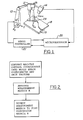
- Figure 1 contains a schematic representation of a robot manipulator 10 including end effector 12.
- the end effector may comprise a sealant application gun, a paint spray gun, a welding device, a drill, or other types of tools known to those skilled in the art and suggested by this disclosure.
- robot manipulator 10 is shown as causing end effector 12 to traverse workpiece 18 along locus of end effector operation 19.
- Locus 19 could comprise, without limitation, a weld seam, a seam to which sealer is to be applied, or a region which is to be machined by end effector 12.
- Camera 14 and laser light source 16 are mounted adjacent to end effector 12. Although a laser light source is described herein, those skilled in the art will appreciate in view of this disclosure that similar structured light devices which project a plane of light upon the workpiece could be employed in practicing the present invention.
- Laser light source 16 projects a plane of light which intersects with workpiece 18 along line 23 of Figure 1.
- Camera 14 works in conjunction with microprocessor 20 to determine the offset of locus 19 by a triangulation method, for example.
- Such methods are known in the art to which this invention pertains and in general involve storing an idealized image of the workpiece, which is compared with an actual image which is created as camera 14 views the workpiece, including locus 19 at a 45 degree angle from the plane of laser light.
- U.S. Patent 4,188,544 which discloses a method and apparatus for determining the offset location of a workpiece, is hereby incorporated by reference into this workpiece, is hereby incorporated by reference into this specification.
- a method and system according to the present invention may be employed with as few as a single measurement point, or as many as twenty or more points. Although a few points may be adequate for simple structures such as linear seams, more complex structures such as an automobile door may require 5 or 6 points. Those skilled in the art will appreciate in view of this disclosure that the use of additional points may require additional travel of the camera to added locations, which will, of course, increase the cycle time of the operation being performed by the robot.
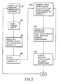
- the computer moves to block 36.
- the offset array is multiplied by a previously prepared conversion matrix "M" to yield a six component vector.
- the vector has the following form: where p x , p y , and p z and x , y and z represent the three-dimensional offsets and rotations of the workpiece from its idealized location.
- correction matrix T is formed according to the following arrangement:
- the computer moves to block 40, wherein the coordinates of the idealized robot manipulator path, as set forth in a world coordinate system, are corrected by multiplying each of the preprogrammed coordinates by matrix T.
- the corrected world path coordinates are transformed at block 42 to machine control coordinates using any one of several known methods for performing this operation.
- One such method is described in "Kinematics of Major Robot Linkage", which was authored by the present inventors and which was published in the Proceedings of the 13th. International Symposium on Industrial Robots, 1983, Volume 2. This article is hereby incorporated by reference herein.
- the corrected machine control coordinates are sent to servo controller 22 via microprocessor 20 so that the robot's end effector 12 may be guided precisely along locus 19 in workpiece 18.
- the steps contained within blocks 40-44 are repeated for each of the waypoints along the path the robot manipulator is programmed to traverse. With each new workpiece, the entire sequence is repeated, beginning with block 32.
- Preparation of conversion matrix "M" is performed during a teaching phase of robot programming. Because the conversion matrix is formed only once, a system and method according to the present invention provides an economical use of computing resources insofar as the correction of the machine control coordinates to compensate for successive alignments of workpieces requires fewer calculations than conventional systems employing such methods as least squares or other types of solutions requiring the solving of large numbers of simultaneous equations representing differences between a preprogrammed robot path and the path necessitated by the actual orientation of a workpiece.
- the first step in the formation of conversion matrix "M" is shown at block 24, Figure 2, wherein machine control coordinates of the expected path of end effector 12 are converted into world space coordinates and unit direction vectors for a series of waypoints prescribing the anticipated path of end effector 12.
- Figure 1 shows the architecture of the world space coordinate and unit measurement direction vector systems used with a system and method according to this invention.
- measurement matrix H is formed with the components of the unit measurement direction vectors and the components of the vector cross products of the world space coordinates and the unit measurement direction vectors.
- measurement matrix H is inverted to form conversion matrix M.
- This inversion may be done according to a variety of methods known to those skilled in the art and suggested by this disclosure. However, the decomposition method which is known to those skilled in the arts to which this invention pertains has proven to be useful for performing this operation.
Landscapes
- Engineering & Computer Science (AREA)
- Robotics (AREA)
- Mechanical Engineering (AREA)
- Human Computer Interaction (AREA)
- Manufacturing & Machinery (AREA)
- Physics & Mathematics (AREA)
- General Physics & Mathematics (AREA)
- Automation & Control Theory (AREA)
- Numerical Control (AREA)
- Manipulator (AREA)
Applications Claiming Priority (2)
| Application Number | Priority Date | Filing Date | Title |
|---|---|---|---|
| US249020 | 1988-09-26 | ||
| US07/249,020 US4945493A (en) | 1988-09-26 | 1988-09-26 | Method and system for correcting a robot path |
Publications (2)
| Publication Number | Publication Date |
|---|---|
| EP0361663A2 true EP0361663A2 (de) | 1990-04-04 |
| EP0361663A3 EP0361663A3 (de) | 1990-06-06 |
Family
ID=22941702
Family Applications (1)
| Application Number | Title | Priority Date | Filing Date |
|---|---|---|---|
| EP89308286A Withdrawn EP0361663A3 (de) | 1988-09-26 | 1989-08-15 | Verfahren und Einrichtung für eine Roboterbahn |
Country Status (2)
| Country | Link |
|---|---|
| US (1) | US4945493A (de) |
| EP (1) | EP0361663A3 (de) |
Cited By (13)
| Publication number | Priority date | Publication date | Assignee | Title |
|---|---|---|---|---|
| FR2666761A1 (fr) * | 1990-09-18 | 1992-03-20 | Aerospatiale | Procede et dispositif de guidage de moyens de prehension d'un robot. |
| WO1995007217A1 (de) * | 1993-09-11 | 1995-03-16 | Putzmeister-Werk Maschinenfabrik Gmbh | Verfahren zur bearbeitung eines objekts mittels eines mindestens eine bearbeitungseinheit aufweisenden bearbeitungsgeräts |
| EP0937974A3 (de) * | 1998-02-23 | 1999-12-15 | Fanuc Ltd | Roboter und Verfahren zur Kalibrierung eines auf dem Roboter befestigten Kraftsensors |
| EP1125695A3 (de) * | 2000-02-15 | 2002-07-24 | General Electric Company | Robotischer Laserzeiger |
| FR2846413A1 (fr) * | 2002-10-24 | 2004-04-30 | Luc Vergnaud | Dispositif de numerisation sans contact d'un objet en 3 dimensions |
| WO2004026673A3 (de) * | 2002-09-13 | 2004-07-22 | Daimler Chrysler Ag | Verfahren und vorrichtung zur lagegenauen montage eines anbauteils an eine fahrzeugkarosserie |
| WO2004108363A1 (en) * | 2003-06-11 | 2004-12-16 | Abb Ab | A method for fine tuning of a robot program |
| WO2016078760A1 (de) * | 2014-11-21 | 2016-05-26 | Kuka Roboter Gmbh | Verfahren und system zur korrektur einer bearbeitungsbahn eines robotergeführten werkzeugs |
| CN106926233A (zh) * | 2015-12-29 | 2017-07-07 | 楚天科技股份有限公司 | 一种平面机械手运动路径的规划方法 |
| WO2018072134A1 (en) * | 2016-10-19 | 2018-04-26 | Abb Schweiz Ag | Robot processing path automatic compensation method |
| CN108705530A (zh) * | 2018-04-10 | 2018-10-26 | 广州启帆工业机器人有限公司 | 一种工业机器人路径自动修正的方法及系统 |
| WO2019025130A1 (de) * | 2017-07-31 | 2019-02-07 | Siemens Aktiengesellschaft | Bearbeitung von werkstücken mit fehlerkompensation |
| DE112020007606B4 (de) | 2020-09-14 | 2024-06-13 | Mitsubishi Electric Corporation | Robotersteuervorrichtung |
Families Citing this family (41)
| Publication number | Priority date | Publication date | Assignee | Title |
|---|---|---|---|---|
| US5208763A (en) * | 1990-09-14 | 1993-05-04 | New York University | Method and apparatus for determining position and orientation of mechanical objects |
| US5083073A (en) * | 1990-09-20 | 1992-01-21 | Mazada Motor Manufacturing U.S.A. Corp. | Method and apparatus for calibrating a vision guided robot |
| JPH04169905A (ja) * | 1990-11-01 | 1992-06-17 | Fanuc Ltd | 3次元レーザの座標変換方式 |
| US5535306A (en) * | 1993-01-28 | 1996-07-09 | Applied Materials Inc. | Self-calibration system for robot mechanisms |
| US5390128A (en) * | 1993-04-12 | 1995-02-14 | Cargill Detroit Corporation | Robotic processing and inspection system |
| JPH07266272A (ja) * | 1994-03-29 | 1995-10-17 | Nippon Telegr & Teleph Corp <Ntt> | マニピュレータ用追従方法及び装置 |
| JP3394322B2 (ja) | 1994-05-19 | 2003-04-07 | ファナック株式会社 | 視覚センサを用いた座標系設定方法 |
| US6789039B1 (en) * | 2000-04-05 | 2004-09-07 | Microsoft Corporation | Relative range camera calibration |
| US6591160B2 (en) * | 2000-12-04 | 2003-07-08 | Asyst Technologies, Inc. | Self teaching robot |
| NO317898B1 (no) * | 2002-05-24 | 2004-12-27 | Abb Research Ltd | Fremgangsmate og system for a programmere en industrirobot |
| SE525108C2 (sv) * | 2002-12-30 | 2004-11-30 | Abb Research Ltd | Metod och system för programmering av en industrirobot, datorprogramprodukt, datorläsbart medium samt användning |
| RU2250498C2 (ru) * | 2003-02-25 | 2005-04-20 | Курский государственный технический университет | Способ автоматической адаптивной трехмерной калибровки бинокулярной системы технического зрения и устройство для его реализации |
| SE526119C2 (sv) * | 2003-11-24 | 2005-07-05 | Abb Research Ltd | Metod och system för programmering av en industrirobot |
| US7236854B2 (en) * | 2004-01-05 | 2007-06-26 | Abb Research Ltd. | Method and a system for programming an industrial robot |
| RU2286598C1 (ru) * | 2005-03-01 | 2006-10-27 | Государственное образовательное учреждение высшего профессионального образования "Курский государственный технический университет" | Способ внешней калибровки бинокулярной системы технического зрения |
| DE602008000416D1 (de) * | 2008-02-13 | 2010-01-28 | Abb As | System und Verfahren zur Visualisierung von Verfahrensfehlern |
| CN102371584B (zh) * | 2010-08-11 | 2014-02-19 | 上海高威科电气技术有限公司 | 可扩展的工业机器人控制系统 |
| EP2931485B1 (de) * | 2012-12-14 | 2023-09-13 | ABB Schweiz AG | Freihändiges roboterpfad-training |
| ES2899585T3 (es) | 2016-07-15 | 2022-03-14 | Fastbrick Ip Pty Ltd | Pluma para transporte de material |
| JP7061119B2 (ja) * | 2016-07-15 | 2022-04-27 | ファストブリック・アイピー・プロプライエタリー・リミテッド | 車両に組み込まれた煉瓦/ブロック敷設機 |
| CN111095355B (zh) | 2017-07-05 | 2023-10-20 | 快砖知识产权私人有限公司 | 实时定位和定向跟踪器 |
| US11958193B2 (en) | 2017-08-17 | 2024-04-16 | Fastbrick Ip Pty Ltd | Communication system for an interaction system |
| AU2018317941B2 (en) | 2017-08-17 | 2023-11-09 | Fastbrick Ip Pty Ltd | Laser tracker with improved roll angle measurement |
| CN111212799B (zh) | 2017-10-11 | 2023-04-14 | 快砖知识产权私人有限公司 | 用于传送物体的机器以及与其一起使用的多隔间转盘 |
| MX386786B (es) | 2018-04-30 | 2025-03-19 | Path Robotics Inc | Escaner láser que rechaza la reflexión. |
| US12311546B2 (en) | 2018-07-16 | 2025-05-27 | Fastbrick Ip Pty Ltd | Active damping system |
| WO2020014737A1 (en) | 2018-07-16 | 2020-01-23 | Fastbrick Ip Pty Ltd | Backup tracking for an interaction system |
| US10926416B2 (en) | 2018-11-21 | 2021-02-23 | Ford Global Technologies, Llc | Robotic manipulation using an independently actuated vision system, an adversarial control scheme, and a multi-tasking deep learning architecture |
| CN115443363A (zh) | 2020-04-22 | 2022-12-06 | 快砖知识产权私人有限公司 | 块传送装置及用于与其一起使用的改进的夹紧组件 |
| CN113618728A (zh) * | 2020-05-09 | 2021-11-09 | 北京配天技术有限公司 | 机器人运动轨迹的补偿方法、装置及计算机存储介质 |
| AU2021304545B2 (en) | 2020-07-08 | 2025-12-04 | Fastbrick Ip Pty Ltd | Adhesive application system |
| WO2022016152A1 (en) | 2020-07-17 | 2022-01-20 | Path Robotics, Inc. | Real time feedback and dynamic adjustment for welding robots |
| CN112659121B (zh) * | 2020-12-09 | 2024-03-29 | 北京配天技术有限公司 | 机器人磨轮半径补偿方法、装置、机器人及存储介质 |
| MX2023009878A (es) | 2021-02-24 | 2024-01-08 | Path Robotics Inc | Robots soldadores autonomos. |
| US12277369B2 (en) | 2021-10-18 | 2025-04-15 | Path Robotics, Inc. | Generating simulated weld paths for a welding robot |
| CA3239078A1 (en) | 2021-11-19 | 2023-05-25 | Path Robotics, Inc. | Machine learning logic-based adjustment techniques for robots |
| CN114355840B (zh) * | 2021-12-20 | 2024-07-05 | 深圳泰德激光技术股份有限公司 | 多轴机床校正方法、装置、终端及计算机可读存储介质 |
| US12508665B2 (en) | 2022-04-19 | 2025-12-30 | Path Robotics, Inc. | Autonomous assembly robots |
| US12521884B2 (en) | 2022-07-26 | 2026-01-13 | Path Robotics, Inc. | Techniques for multipass welding |
| CN116394240A (zh) * | 2023-03-29 | 2023-07-07 | 安徽省配天机器人集团有限公司 | 轨迹补偿方法、装置及计算机可读存储介质 |
| CN121568816A (zh) * | 2023-07-28 | 2026-02-24 | Abb瑞士股份有限公司 | 用于确定用于加工工件的路径的方法和系统 |
Family Cites Families (12)
| Publication number | Priority date | Publication date | Assignee | Title |
|---|---|---|---|---|
| US4017721A (en) * | 1974-05-16 | 1977-04-12 | The Bendix Corporation | Method and apparatus for determining the position of a body |
| US4146924A (en) * | 1975-09-22 | 1979-03-27 | Board Of Regents For Education Of The State Of Rhode Island | System for visually determining position in space and/or orientation in space and apparatus employing same |
| US4402053A (en) * | 1980-09-25 | 1983-08-30 | Board Of Regents For Education For The State Of Rhode Island | Estimating workpiece pose using the feature points method |
| US4380696A (en) * | 1980-11-12 | 1983-04-19 | Unimation, Inc. | Method and apparatus for manipulator welding apparatus with vision correction for workpiece sensing |
| JPH065486B2 (ja) * | 1981-03-26 | 1994-01-19 | 株式会社安川電機 | ロボットの軌跡制御方法 |
| US4433382A (en) * | 1981-07-20 | 1984-02-21 | Cincinnati Milacron Inc. | Apparatus for automatically adjusting the programmed location of a robot arm |
| US4432063A (en) * | 1981-10-06 | 1984-02-14 | Cincinnati Milacron Inc. | Apparatus for automatically moving a robot arm along a nonprogrammed path |
| JPS58177295A (ja) * | 1982-04-07 | 1983-10-17 | 株式会社日立製作所 | ロボット制御装置 |
| US4590578A (en) * | 1983-07-11 | 1986-05-20 | United Technologies Corporation | Off-line programmable robot |
| US4575802A (en) * | 1983-07-11 | 1986-03-11 | United Technologies Corporation | Robot/workpiece orientation |
| US4639878A (en) * | 1985-06-04 | 1987-01-27 | Gmf Robotics Corporation | Method and system for automatically determining the position and attitude of an object |
| US4707647A (en) * | 1986-05-19 | 1987-11-17 | Gmf Robotics Corporation | Gray scale vision method and system utilizing same |
-
1988
- 1988-09-26 US US07/249,020 patent/US4945493A/en not_active Expired - Fee Related
-
1989
- 1989-08-15 EP EP89308286A patent/EP0361663A3/de not_active Withdrawn
Cited By (25)
| Publication number | Priority date | Publication date | Assignee | Title |
|---|---|---|---|---|
| EP0477078A1 (de) * | 1990-09-18 | 1992-03-25 | AEROSPATIALE Société Nationale Industrielle | Verfahren und Einrichtung zur Führung von Robotergreifarmen |
| FR2666761A1 (fr) * | 1990-09-18 | 1992-03-20 | Aerospatiale | Procede et dispositif de guidage de moyens de prehension d'un robot. |
| WO1995007217A1 (de) * | 1993-09-11 | 1995-03-16 | Putzmeister-Werk Maschinenfabrik Gmbh | Verfahren zur bearbeitung eines objekts mittels eines mindestens eine bearbeitungseinheit aufweisenden bearbeitungsgeräts |
| EP0937974A3 (de) * | 1998-02-23 | 1999-12-15 | Fanuc Ltd | Roboter und Verfahren zur Kalibrierung eines auf dem Roboter befestigten Kraftsensors |
| US6382012B2 (en) | 1998-02-23 | 2002-05-07 | Fanuc Ltd. | Method for calibrating force sensor mounted on robot, and robot |
| CZ301571B6 (cs) * | 2000-02-15 | 2010-04-21 | General Electric Company | Kalibracní zamerovac, robotizovaný stroj s kalibracním zamerovacem, a zpusob nastavení robotizovaného stroje prostrednictvím kalibracního zamerovace |
| EP1125695A3 (de) * | 2000-02-15 | 2002-07-24 | General Electric Company | Robotischer Laserzeiger |
| KR100784171B1 (ko) * | 2000-02-15 | 2007-12-10 | 제너럴 일렉트릭 캄파니 | 캘리브레이션 포인터 및 그 사용 방법 |
| WO2004026672A3 (de) * | 2002-09-13 | 2004-09-23 | Daimler Chrysler Ag | Verfahren und vorrichtung zur lagegenauen montage einer klappe an einem bauteil |
| WO2004026673A3 (de) * | 2002-09-13 | 2004-07-22 | Daimler Chrysler Ag | Verfahren und vorrichtung zur lagegenauen montage eines anbauteils an eine fahrzeugkarosserie |
| EP1539562B1 (de) | 2002-09-13 | 2015-06-03 | VMT Vision Machine Technic Bildverarbeitungssysteme GmbH | Verfahren und vorrichtung zur lagegenauen montage eines anbauteils an eine fahrzeugkarosserie |
| WO2004040235A3 (fr) * | 2002-10-24 | 2004-07-01 | Luc Vergnaud | Dispositif de numerisation sans contact d'un objet en 3 dimensions |
| FR2846413A1 (fr) * | 2002-10-24 | 2004-04-30 | Luc Vergnaud | Dispositif de numerisation sans contact d'un objet en 3 dimensions |
| CN100396450C (zh) * | 2003-06-11 | 2008-06-25 | Abb公司 | 用于微调机器人程序的方法 |
| WO2004108363A1 (en) * | 2003-06-11 | 2004-12-16 | Abb Ab | A method for fine tuning of a robot program |
| WO2016078760A1 (de) * | 2014-11-21 | 2016-05-26 | Kuka Roboter Gmbh | Verfahren und system zur korrektur einer bearbeitungsbahn eines robotergeführten werkzeugs |
| CN107073714A (zh) * | 2014-11-21 | 2017-08-18 | 库卡罗伯特有限公司 | 用于修正机器人引导工具的加工轨迹的方法和系统 |
| US10394216B2 (en) | 2014-11-21 | 2019-08-27 | Kuka Deutschland Gmbh | Method and system for correcting a processing path of a robot-guided tool |
| CN106926233A (zh) * | 2015-12-29 | 2017-07-07 | 楚天科技股份有限公司 | 一种平面机械手运动路径的规划方法 |
| CN106926233B (zh) * | 2015-12-29 | 2019-04-16 | 楚天科技股份有限公司 | 一种平面机械手运动路径的规划方法 |
| WO2018072134A1 (en) * | 2016-10-19 | 2018-04-26 | Abb Schweiz Ag | Robot processing path automatic compensation method |
| WO2019025130A1 (de) * | 2017-07-31 | 2019-02-07 | Siemens Aktiengesellschaft | Bearbeitung von werkstücken mit fehlerkompensation |
| CN108705530A (zh) * | 2018-04-10 | 2018-10-26 | 广州启帆工业机器人有限公司 | 一种工业机器人路径自动修正的方法及系统 |
| CN108705530B (zh) * | 2018-04-10 | 2021-01-19 | 广州启帆工业机器人有限公司 | 一种工业机器人路径自动修正的方法及系统 |
| DE112020007606B4 (de) | 2020-09-14 | 2024-06-13 | Mitsubishi Electric Corporation | Robotersteuervorrichtung |
Also Published As
| Publication number | Publication date |
|---|---|
| US4945493A (en) | 1990-07-31 |
| EP0361663A3 (de) | 1990-06-06 |
Similar Documents
| Publication | Publication Date | Title |
|---|---|---|
| US4945493A (en) | Method and system for correcting a robot path | |
| EP0158447B2 (de) | System zum Steuern eines Roboters in Zusammenhang mit einem Drehtisch | |
| EP0188623B1 (de) | Verfahren zum einstellen der werkzeugkoordinaten | |
| FI83176B (fi) | Foerfarande foer styrning av roerelser hos en robot och en styckemanipulator under en robotcells inlaerningsskede. | |
| EP0123214B1 (de) | Verfahren und Vorrichtung zur Betätigungslehre eines Industrieroboters | |
| KR100311663B1 (ko) | 여유축을이용하여물체의외형을추적하는장치및방법 | |
| US5380978A (en) | Method and apparatus for assembly of car bodies and other 3-dimensional objects | |
| US4590578A (en) | Off-line programmable robot | |
| CA1275670C (en) | Kinematic parameter identification for robotic manipulators | |
| JPH023808A (ja) | ロボット・システム | |
| Jinno et al. | Development of a force controlled robot for grinding, chamfering and polishing | |
| Khosla et al. | An algorithm for seam tracking applications | |
| JP2728399B2 (ja) | ロボツトの制御方法 | |
| US4972347A (en) | Method and apparatus for determining the correct tool dimensions for a three dimensional tool mounted on a manipulator | |
| JPH06131032A (ja) | ロボット装置およびロボット装置のティ−チング方法。 | |
| EP0172257A1 (de) | Gradeinteilungsverfahren für eine automatische schweissmaschine | |
| CN112297003A (zh) | 设定机器人坐标系的装置、机器人控制装置、机器人系统以及方法 | |
| EP0359822B1 (de) | Bahnsteuerverfahren für roboter | |
| TSAI et al. | Mathematical model for robotic arc-welding off-line programming system | |
| JPS6111815A (ja) | ロボツトの位置ズレ補正システム | |
| KR100336459B1 (ko) | 로봇의 오프-라인 제어 방법 | |
| Red et al. | Calibration control of robot vertical assembly | |
| Park et al. | Calibration-based absolute localization of parts for multi-robot assembly | |
| Wang et al. | Off-Line Integration Techniques for Robot Path Planning | |
| JP2652444B2 (ja) | ロボットシステム |
Legal Events
| Date | Code | Title | Description |
|---|---|---|---|
| PUAI | Public reference made under article 153(3) epc to a published international application that has entered the european phase |
Free format text: ORIGINAL CODE: 0009012 |
|
| AK | Designated contracting states |
Kind code of ref document: A2 Designated state(s): DE FR GB SE |
|
| PUAL | Search report despatched |
Free format text: ORIGINAL CODE: 0009013 |
|
| AK | Designated contracting states |
Kind code of ref document: A3 Designated state(s): DE FR GB SE |
|
| 17P | Request for examination filed |
Effective date: 19901030 |
|
| 17Q | First examination report despatched |
Effective date: 19921214 |
|
| STAA | Information on the status of an ep patent application or granted ep patent |
Free format text: STATUS: THE APPLICATION IS DEEMED TO BE WITHDRAWN |
|
| 18D | Application deemed to be withdrawn |
Effective date: 19930427 |