EP0346610A2 - Anlage zur Verpackung der Einzelkomponenten eines Mehrstoffgemisches - Google Patents
Anlage zur Verpackung der Einzelkomponenten eines Mehrstoffgemisches Download PDFInfo
- Publication number
- EP0346610A2 EP0346610A2 EP89108360A EP89108360A EP0346610A2 EP 0346610 A2 EP0346610 A2 EP 0346610A2 EP 89108360 A EP89108360 A EP 89108360A EP 89108360 A EP89108360 A EP 89108360A EP 0346610 A2 EP0346610 A2 EP 0346610A2
- Authority
- EP
- European Patent Office
- Prior art keywords
- container
- weighing
- filling
- bag
- station
- Prior art date
- Legal status (The legal status is an assumption and is not a legal conclusion. Google has not performed a legal analysis and makes no representation as to the accuracy of the status listed.)
- Granted
Links
Images
Classifications
-
- B—PERFORMING OPERATIONS; TRANSPORTING
- B65—CONVEYING; PACKING; STORING; HANDLING THIN OR FILAMENTARY MATERIAL
- B65B—MACHINES, APPARATUS OR DEVICES FOR, OR METHODS OF, PACKAGING ARTICLES OR MATERIALS; UNPACKING
- B65B1/00—Packaging fluent solid material, e.g. powders, granular or loose fibrous material, loose masses of small articles, in individual containers or receptacles, e.g. bags, sacks, boxes, cartons, cans, or jars
- B65B1/30—Devices or methods for controlling or determining the quantity or quality or the material fed or filled
- B65B1/32—Devices or methods for controlling or determining the quantity or quality or the material fed or filled by weighing
-
- B—PERFORMING OPERATIONS; TRANSPORTING
- B65—CONVEYING; PACKING; STORING; HANDLING THIN OR FILAMENTARY MATERIAL
- B65B—MACHINES, APPARATUS OR DEVICES FOR, OR METHODS OF, PACKAGING ARTICLES OR MATERIALS; UNPACKING
- B65B1/00—Packaging fluent solid material, e.g. powders, granular or loose fibrous material, loose masses of small articles, in individual containers or receptacles, e.g. bags, sacks, boxes, cartons, cans, or jars
- B65B1/04—Methods of, or means for, filling the material into the containers or receptacles
- B65B1/10—Methods of, or means for, filling the material into the containers or receptacles by rotary feeders
- B65B1/12—Methods of, or means for, filling the material into the containers or receptacles by rotary feeders of screw type
Definitions
- the invention relates to a plant for the production and packaging of a multi-substance mixture according to the preamble of claim 1.
- Known filling and packaging systems for individual components consist of one-component containers with an assigned multi-component scale.
- the production of a certain composition of substances from the individual components takes place in that the additive weighing of the individual components on a balance produces the mixture of substances and then packs it.
- the weighing of chemicals in small quantities for medical technology or other areas must be carried out with high-precision weighing equipment.
- considerable weight differences of the individual substance components can occur, ie a large amount of the first substance is mixed, for example, with a very small amount of a second substance.
- the weighing devices to be used have to cover very large weight ranges, which on the one hand is high technical effort and secondly an inevitable imprecision due to large weight ranges.
- Additive weighing of individual components also has the disadvantage that the weighing process takes a very long time, since this is only completed when all individual components have been weighed on the multi-component scale.
- a number of such multi-component scales or multi-component filling stations could indeed be arranged one behind the other. However, these cannot work together because each filling station carries out a self-contained process for the complete weighing and filling of the individual components.
- the invention is based on the object of proposing a system for the production and packaging of a multi-material mixture in which the aforementioned disadvantages are avoided and with which, in particular, highly accurate weighing and combining of individual components at a high throughput or filling speed is made possible.
- the invention is based on the knowledge that an extremely precise weighing process in an economically justifiable degree and at high speed is only sensible with a one-component weighing device. Therefore, the invention proposes the series connection of one-component containers with associated filling devices for recipes consisting of one or more individual substances.
- a filling device consists of a discharge device, possibly specially adapted to the substance to be filled, and a downstream weighing device and a transfer device of the weighed individual substance into a container. This container is then fed to a next filling station with a further individual substance in cycles, it also being possible, if appropriate, for the containers to be stationary and the fill-up containers with the associated discharge, weighing and transfer device to be clocked past them.
- the individual stations can each be specifically adapted to the substance to be discharged.
- one or more specific stations have a cooling device for temperature-sensitive products, or that the discharge and weighing devices are specially adapted to the respective substance.
- the discharge and weighing devices are specially adapted to the respective substance.
- a special feature of the invention is the dust-free treatment of the materials, in particular the type of loading of the fill-up containers.
- they are fed, for example, from sacks with individual chemicals, the emptied sacks being conveyed in a conveying channel for empty sacks by vacuum to a sack compressor located at the end of the system.
- a sack compressor located at the end of the system.
- an additional suction device is provided which also sucks off the dust or vapors via the sack channel.
- an electronically controlled discharge device for. B. in the form of an electronically controlled screw transport of the individual components from the hopper, the control taking place depending on the weighing process.
- Essential to the invention is also a hemispherical weighing container assigned to the weighing station, which enables complete emptying of the weighed goods by rotation through 180 °. It is also advantageous that the exact amount to be observed is determined by a controlled valve.
- Another special feature of the invention lies in the special closing device of the plastic bag used.
- the upper edge of the plastic bag which is turned over the edge of the container, is sucked into a ring-shaped upper slot by means of a suction device and pulled apart by means of two laterally arranged grippers in order to then be welded together.
- a special bag ejection station with a downstream bag check weigher is also advantageous.
- the system according to the invention has the advantage that it is almost fully automatic, i. H. can usually only be operated with a supervisor. High throughput rates can be achieved with the utmost precision and accuracy of the filling and packaging process.
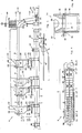
- Plant 1 shown schematically in side view in FIG. 1 and in plan view in FIG. 2, is used in the special exemplary embodiment for weighing and packaging individual chemicals. In general, up to about 10 individual components for the production of a specific recipe from z. B. 44 different individual components selected and metered.
- Filling stations 4 to 6 are arranged one behind the other along a linear conveyor belt 2 with individual containers 3 displaceable thereon. As can be seen from FIG. 2 in a top view, 4 to 6 each have two filling containers 7, 7 'arranged side by side so that in the illustration according to FIG. 2, for example, twenty-two pairs of filling containers connected in series, ie a total of forty four filling containers are provided.
- the numbered fillers 1 to 4 (filling stations 4), the fillers 5 to 10 (filling stations 5) and the fillers 11 to 44 (filling stations 6) are each listed in the same design in the exemplary embodiment.
- the individual filling stations 4 to 6 with respective fill-up containers 7 are loaded with individual chemicals from above. This happens, for example, in that the individual chemicals delivered in bags are poured into the respective fill-up container 7 as a silo or storage container.
- a special feature of the system is that the cut and emptied plastic bags 8 are sucked off in a special conveyor channel 9 for empty bags and fed to a special bag compressor 10.
- the conveying channel serves as a suction channel for the dust or vapors which arise when the chemicals are poured into the filling container 7.
- a special suction and filter device 11 is provided for producing the negative pressure in the delivery line 9 and filtering the dust or vapors.
- the suction and filter device 11 consists of a funnel-shaped container 12 in the lower region and an upper central filter 13, and a fan 14 arranged behind the filter for generating the negative pressure.
- a container 15 for residues from the container 12 is arranged below the funnel-shaped container 12.
- the conveyor channel 9 crosses the container 12 and leads via the subsequent line 9 'to the bag compressor 10.
- the empty bags 8 are pressed into bales 17 or packaging.
- each filler container 7 has in its upper region a sack filler 18 with a fill opening 19 for the respective filler container 7 and an empty sack insertion opening 20 for the conveying and suction channel 9 for the empty sacks 8.
- the filling stations 5, d. H. the individual containers 5 to 10 are equipped in the exemplary embodiment with an outer water cooling jacket 21 for temperature-sensitive chemicals.
- a combined discharge, weighing and transfer device 22 for the individual component is assigned to each fill-up container 7 in its lower region. This also applies to the arrangement shown in Fig. 2 with side-by-side filling containers 7, 7 '.
- the discharge, weighing and transfer device of the rear filler 7 ' is identified by reference numeral 22'.
- the first filling station type 4 (individual containers 1 to 4) shown in FIG. 1 has a discharge device 23 which consists of two electronically controlled screw conveyors 24 and an electronically controlled shut-off valve 25 arranged one above the other.
- the double screw conveyor serves to adapt the metering capacity to the material to be conveyed or to the weight to be weighed out of the filling container 7.
- the screw speed of the screw conveyor 24 is electronically controlled by the weighing device 26 arranged below it, which has a hemispherical weighing container 28 on an arm 27 which can be rotated through 180 °. Due to the electronically controlled screw transport of the screw conveyor 24, the quantity conveyed by the screw into the hemispherical container 28 is measured via the weighing device and the screw drive is continuously regulated back towards the end of the measuring process. An exact metering can finally be ensured by the electronically controlled shut-off valve 25 provided between the screw conveyor 24 and the weighing container 28.
- the discharge, weighing and transfer devices 22 of the further filling stations 5 and 6 do not differ in principle from that of the filling station 4. As shown in FIG. 1, these can have, for example, a discharge device 23 designed only with a screw conveyor 24, the combined one Discharge, weighing and transfer process can each be adapted to the specific component to be treated or the substance in the respective dumping container.
- additional suction lines 29 are also provided between the discharge, weighing and transfer device 22 and the suction and filter device 11 in order to keep this area completely dust-free by suction of dust and vapors.
- a single container 3 is arranged below the discharge, weighing and transfer device 22 in order to receive the substance to be removed from the respective filling station.
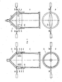
- the containers 3 are loaded manually or automatically with a plastic bag 30, the upper edge 31 of the plastic bag 30 being turned over the container edge 32 is. 3, the container 3 loaded with a plastic bag 30 is covered with an eyeglass-shaped cover 33, so that the outer edge 31 of the plastic bag is protected behind a cover and cannot collect dust.
- the discharge, weighing and transfer device 22 has in its lower region of the transfer device 34 a connecting flange 35 which interacts with the eyeglass-shaped cover 33 and enables the material from the transfer device 34 to be filled into the plastic bag 30 without dust from the outside.
- the refilling process takes place by a 180 ° rotary movement of the hemispherical weighing container 28, so that the material contained therein is emptied.
- the light barrier 36 checks for the plastic bag inserted in the container 3.
- the individual containers 3 shown in FIG. 1 are pushed one behind the other on the linear conveyor belt 2, so that no play can occur between the individual containers 3. With a large number of filling stations 4 to 6 connected in series, this is expedient in order to obtain the most precise and simple positioning of the individual containers below the respective filling station.
- the last filling station 6, z. B. passed single station 44 or a preceding station, it is fed to a special stationary welding station 37 shown in FIGS. 4a-d.
- the eyeglass-shaped lid 33 is folded away to the side and a separate sack rim suction device 38 is placed over the rim 32 of the container.
- the sack edge suction device 38 has a slotted annular channel 39, in which the upper edge 31 of the plastic bag 30 is sucked in by negative pressure (edge 31 ').
- the upper edge of the bag 31 is gripped by two opposite grippers 40, 40 'projecting through the side slots and pulled apart laterally (see FIG.
- the welding station 37 is followed by a discharge station 42 for the filled plastic bags 30.
- the container 3 is equipped in its lower region with a pivotable flap 43, the flap 43 being opened gently and gradually by means of a cam control 44 in such a way that the sack 30 does not suddenly arrives at the control weighing station 45 arranged below the discharge station 42.
- the exact total weight of the filled individual components is checked again by the control weighing station 45 and faulty batches are sorted out if necessary.
- the weighed end product then arrives on a conveyor belt 46 for further transport.
- the container emptied in the discharge station 42 is transported further on the conveyor belt 2, a cam control 47 or an equivalent mechanism leading to the closing of the pivotable flap 43.
- the stations 37, 42, 45 arranged after the last filling station 6 can be stations running parallel to the filling stations 4 to 6 be carried out to shorten the total length of the system.
- An additional swivel station 48 for swiveling the eyeglass-shaped cover away from the welding station 37 is indicated in FIG. 2.
- a faulty batch belt 49 is drawn in after the control weighing station 45, the faulty batches being sorted out from the system.
- the empty containers 3 are filled manually or automatically with empty plastic sacks 30 in a sack filling station 50 before they are returned to the first filling container 7 in the first filling station 4 in the circuit. Before that, the light control barrier 26 is still provided for the bag control.
- the invention is not restricted to the exemplary embodiment shown and described. Rather, it also encompasses all professional training courses without their own inventive content.
- the filling stations 4 to 6 can also be arranged on a circular or oval ring, the individual containers 3 on the conveyor belt 2 again preferably being clocked under the filling stations.
- the further processing stations 37, 42, 45 can be located inside or outside the circular or oval transport arrangement.
Landscapes
- Engineering & Computer Science (AREA)
- Mechanical Engineering (AREA)
- Quality & Reliability (AREA)
- Basic Packing Technique (AREA)
- Agricultural Chemicals And Associated Chemicals (AREA)
Abstract
Description
- Die Erfindung betrifft eine Anlage zur Herstellung und Verpackung eines Mehrstoffgemisches nach dem Oberbegriff des Anspruchs 1.
- Bekannte Abfüll- und Verpackungsanlagen für Einzelkomponenten bestehen aus Einkomponentenbehältern mit einer zugeordneten Mehrkomponentenwaage. Die Herstellung einer bestimmten Stoffzusammensetzung aus den Einzelkomponenten geschieht dadurch, daß durch additives Zuwiegen der einzelnen Komponenten auf einer Waage das Stoffgemisch hergestellt und anschließend verpackt wird. Insbesondere das Verwiegen von Chemikalien in kleinen Mengen für die Medizintechnik oder sonstige Gebiete muß mit hochpräzisen Wiegeeinrichtungen vorgenommen werden. In jeder abzuwiegenden Charge können dabei aber erhebliche Gewichtsunterschiede der einzelnen Stoffkomponenten auftreten, d. h. es wird eine große Menge des ersten Stoffes beispielsweise mit einer sehr kleinen Menge eines zweiten Stoffes vermischt. Die zu verwendenden Wiegeeinrichtungen müssen hierfür sehr große Gewichtsbereiche überdecken, was zum einen einen hohen technischen Aufwand und zum anderen eine letztlich nicht vermeidbare Ungenauigkeit durch zu große Gewichtsbereiche mit sich bringt. Weiterhin hat das additive Verwiegen von Einzelkomponenten den Nachteil, daß der Wiegevorgang sehr lange dauert, da dieser erst abgeschlossen ist, wenn alle Einzelkomponenten auf der Mehrkomponentenwaage abgewogen sind. Es könnten zwar mehrere derartige Mehrkomponentenwaagen bzw. Mehrkomponentenabfüllstationen hintereinander angeordnet sein. Diese können jedoch nicht im Verbund miteinander arbeiten, da jede Abfüllstation einen in sich abgeschlossenen Arbeitsvorgang für das komplette Abwiegen und Abfüllen der Einzelkomponenten vornimmt.
- Der Erfindung liegt die Aufgabe zugrunde, eine Anlage zur Herstellung und Verpackung eines Mehrstoffgemisches vorzuschlagen, bei welcher die vorgenannten Nachteile vermieden werden und mit welcher insbesondere ein hochgenaues Abwiegen und Zusammenführen von Einzelkomponenten bei einer hohen Durchsatzleistung bzw. Abfüllgeschwindigkeit ermöglicht wird.
- Diese Aufgabe wird ausgehend von einer Anlage der einleitend bezeichnenden Art erfindungsgemäß durch die kennzeichnenden Merkmale des Anspruchs 1 gelöst.
- Insbesondere bei der Verpackung von Chemikalien wird die Forderung einer absoluten staubfreien Behandlung erhoben. Diese Nebenaufgabe wird gemäß dem unechten Unteranspruch 2 durch eine spezielle Leersackabsaug- und Sackverdichtereinrichtung gelöst.
- Eine weitere spezielle Teilaufgabe liegt in der staubfreien Einfüllung der Einzelkomponenten beispielsweise in einen Kunststoffsack und einer zuverlässigen Verschließung dieses Behältnisses. Dies wird erfindungsgemäß durch den unechten Unteranspruch 6 gelöst. Gleiches gilt für die vorteilhafte Lösung der kombinierten Austrags-, Wiege- und Übergabevorrichtung nach dem unechten Unteranspruch 4.
- Die übrigen Unteransprüche betreffen jeweils vorteilhafte und zweckmäßige Verbesserungen des übergeordneten Erfindungsgedankens.
- Der Erfindung liegt die Erkenntnis zugrunde, daß ein äußerst präziser Wiegevorgang in wirtschaftlich vertretenbarem Maße und mit hoher Geschwindigkeit nur mit einer Einkomponentenwiegeeinrichtung sinnvoll ist. Deshalb schlägt die Erfindung die Hintereinanderschaltung von Einkomponentenbehälter mit jeweils zugehöriger Abfüllvorrichtung für aus ein oder mehreren Einzelstoffen bestehenden Rezepturen vor. Eine solche Abfüllvorrichtung besteht aus einer, ggf. speziell an den abzufüllenden Stoff angepaßten Austragsvorrichtung und einer nachgeschalteten Wiegeeinrichtung sowie einer Übergabevorrichtung des abgewogenen Einzelstoffes in einen Behälter. Dieser Behälter wird dann einer nächsten Abfüllstation mit einem weiteren Einzelstoff taktweise zugeführt, wobei ggf. auch die Behälter stationär und die Aufschüttbehälter mit zugehöriger Austrags-, Wiege- und Übergabevorrichtung an diesen vorbeigetaktet werden können. Durch die erfindungsgemäße Anordnung können die einzelnen Stationen jeweils speziell auf den auszutragenden Stoff abgestimmt werden. Beispielsweise ist es möglich, daß eine oder mehrere bestimmte Stationen eine Kühlvorrichtung für temperaturempfindliche Produkte aufweisen oder daß die Austrags- und Wiegevorrichtungen speziell dem jeweiligen Stoff angepaßt sind. Selbstverständlich wird man versuchen eine weitgehende Vereinheitlichung der Einzelbauteile aus Kostengründen anzustreben.
- Eine Besonderheit der Erfindung liegt in der möglichst staubfreien Behandlung der Stoffe, insbesondere in der Beschickungsart der Aufschüttbehälter. Hierfür werden diese beispielsweise aus Säcken mit einzelnen Chemikalien beschickt, wobei die geleerten Säcke in einem Förderkanal für Leersäcke durch Unterdruck zu einem am Ende der Anlage befindlichen Sackverdichter gefördert werden. Um die eventuell schädlichen Staubbildungen und Dämpfe der Chemikalien abzusaugen, ist eine zusätzliche Saugvorrichtung vorgesehen, die ein Absaugen des Staubes bzw. der Dämpfe ebenfalls über den Sackkanal bewerkstelligt.
- Erfindungswesentlich und vorteilhaft ist weiterhin die Kombination einer elektronisch gesteuerten Austragsvorrichtung, z. B. in Form eines elektronisch gesteuerten Schneckentransports der Einzelkomponenten aus dem Aufschüttbehälter, wobei die Steuerung in Abhängigkeit des Wiegevorgangs erfolgt. Erfindungswesentlich ist auch ein der Wiegestation zugeordneter halbkugelförmiger Wiegebehälter, der durch Drehung um 180° eine vollständige Entleerung des gewogenen Gutes ermöglicht. Vorteilhaft ist weiterhin, daß die exakt einzuhaltende Menge durch ein gesteuertes Ventil bestimmt wird.
- Eine weitere Besonderheit der Erfindung liegt in der speziellen Verschließeinrichtung des verwendeten Kunststoffsacks. Hierzu wird über eine spezielle Vorrichtung der über den Behälterrand umgestülpte obere Rand des Kunststoffsacks durch eine Ansaugung in einen ringförmigen oberen Schlitz eingesaugt und mittels zwei seitlich angeordneten Greifern auseinander gezogen, um danach zusammengeschweißt zu werden.
- Vorteilhaft ist weiterhin eine spezielle Beutelabwurfstation mit nachgeschalteter Beutelkontrollwaage.
- Die erfindungsgemäße Anlage hat den Vorteil, daß sie nahezu vollautomatisch, d. h. normalerweise lediglich mit einer Aufsichtsperson betrieben werden kann. Dabei sind hohe Durchsatzleistungen erreichbar, bei einer äußersten Präzision und Genauigkeit des Abfüll- und Verpackungsvorganges.
- Weitere erfindungswesentliche Einzelheiten und Besonderheiten sind in der Zeichnung dargestellt und anhand des nachfolgend beschriebenen Ausführungsbeispiels näher erläutert. Es zeigen
- Fig. 1 ein Anlagenschema der erfindungsgemäßen Anlage,
- Fig. 2 eine Draufsicht auf eine schematisch dargestellte Anlage,
- Fig. 3 den Aufbau des Behälterverschlusses mit Anschluß zur Abfüllstation und
- Fig. 4a - d die nähere Darstellung der erfindungsgemäßen Sackrandansaugung mit Schweißstation.
- Die in Fig. 1 in Seitenansicht sowie in Fig. 2 in Draufsicht schematisch dargestellte Anlage 1 dient im speziellen Ausführungsbeispiel zur Abwiegung und Verpackung von Einzelchemikalien. Im allgemeinen werden bis zu ca. 10 Einzelkomponenten zur Herstellung einer bestimmten Rezeptur aus z. B. 44 verschiedenen Einzelkomponenten ausgewählt und zudosiert.
- Längs eines linearen Transportbandes 2 mit darauf verschiebbaren Einzelbehältern 3 sind Abfüllstationen 4 bis 6 hintereinander angeordnet. Wie aus Fig. 2 in Draufsicht ersichtlich, sind an jeder Abfüllstation 4 bis 6 jeweils zwei Aufschüttbehälter 7, 7′ paarweise nebeneinander angeordnet, so daß in der Darstellung nach Fig. 2 beispielsweise zweiundzwanzig hintereinander geschaltete Aufschüttbehälterpaare, d. h. insgesamt vierundvierzig Aufschüttbehälter vorgesehen sind. Dabei sind im Ausführungsbeispiel die durchnummerierten Aufschüttbehälter 1 bis 4, (Abfüllstationen 4), die Aufschüttbehälter 5 bis 10 (Abfüllstationen 5) und die Aufschüttbehälter 11 bis 44 (Abfüllstationen 6) in jeweils gleicher Bauweise aufgeführt.
- Es können demnach vierundvierzig unterschiedliche Stoffe in drei verschiedenen Abfüllstationstypen 4 bis 6 behandelt werden, wobei vorzugsweise aus diesen Stoffen eine Rezeptur ausgewählt wird.
- Die einzelnen Abfüllstationen 4 bis 6 mit jeweiligen Aufschüttbehältern 7 werden von oben her mit Einzelchemikalien beschickt. Dies geschieht beispielsweise dadurch, daß die in Säcken angelieferten Einzelchemikalien in den jeweiligen Aufschüttbehälter 7 als Silo oder Lagerungsbehälter eingeschüttet werden. Dabei liegt eine Besonderheit der Anlage darin, daß die aufgeschnittenen und entleerten Kunststoffsäcke 8 in einem speziellen Förderkanal 9 für Leersäcke abgesaugt und einem speziellen Sackverdichter 10 zugeführt werden. Gleichzeitig dient der Förderkanal als Absaugkanal für die beim Einfüllen der Chemikalien in den Aufschüttbehälter 7 entstehenden Staubentwicklungen oder Dämpfe. Hierfür ist eine spezielle Absaug- und Filtervorrichtung 11 zur Herstellung des Unterdrucks in der Förderleitung 9 und der Filterung des Staubes bzw. der Dämpfe vorgesehen. Die Absaug- und Filtervorrichtung 11 besteht aus einem, im unteren Bereich trichterförmigen Behälter 12 und einem oberen Zentralfilter 13, sowie einem hinter dem Filter angeordneten Ventilator 14 zur Erzeugung des Unterdrucks.
- Unterhalb des trichterförmigen Behälters 12 ist ein Behälter 15 für Rückstände aus dem Behälter 12 angeordnet. Der Förderkanal 9 durchquert den Behälter 12 und führt über die anschließende Leitung 9′ zum Sackverdichter 10. Hier findet mittels eines Schneckenförderers 16 ein Verpressen der leeren Säcke 8 in Ballen 17 oder Emballagen statt.
- Sofern die Beschickung der einzelnen Aufschüttbehälter 7 mit einzelnen Chemikalien manuell erfolgt, besitzt jeder Aufschüttbehälter 7 in seinem oberen Bereich eine Sackeinschüttgosse 18 mit Einfüllöffnung 19 zum jeweiligen Aufschüttbehälter 7 sowie eine Leersackeinwurfsöffnung 20 zum Förder- und Absaugkanal 9 für die Leersäcke 8.
- Die Abfüllstationen 5, d. h. die Einzelbehälter 5 bis 10 sind im Ausführungsbeispiel mit einem äußeren Wasserkühlungsmantel 21 für temperaturempfindliche Chemikalien ausgerüstet.
- Jedem Aufschüttbehälter 7 ist in seinem unteren Bereich eine kombinierte Austrags-, Wiege- und Übergabevorrichtung 22 für die Einzelkomponente zugeordnet. Dies gilt auch für die in Fig. 2 dargestellte Anordnung mit nebeneinander positionierten Aufschüttbehälter 7, 7′. Die Austrags-, Wiege- und Übergabevorrichtung des hinteren Aufschüttbehälters 7′ ist mit Bezugszeichen 22′ gekennzeichnet.
- Die in Fig. 1 dargestellte erste Abfüllstationsart 4 (Einzelbehälter 1 bis 4) weist eine Austragsvorrichtung 23 auf, die aus zwei übereinander angeordnete, elektronisch gesteuerte Schneckenförderer 24 und einem elektronisch gesteuerten Absperrventil 25 besteht. Der doppelte Schneckenförderer dient zur Anpassung der Dosierleistung an das zu fördernde Material bzw. an das abzuwiegende Gewicht aus dem Aufschüttbehälter 7.
- Die Schneckendrehzahl des Schneckenförderers 24 wird elektronisch von der darunter angeordneten Wiegevorrichtung 26 geregelt, die an einem, um 180° drehbaren Arm 27 einen halbkugelförmigen Wiegebehälter 28 aufweist. Durch den elektronisch gesteuerten Schneckentransport des Schneckenförderers 24 wird die von der Schnecke in den halbkugelförmigen Behälter 28 geförderte Menge über die Wiegeeinrichtung gemessen und der Schneckenantrieb kontinuierlich gegen Ende des Meßvorgangs zurückgeregelt. Eine exakte Dosierung kann schließlich durch das zwischen den Schneckenförderer 24 und dem Wiegebehälter 28 vorgesehene, elektronisch gesteuerte Absperrventil 25 sichergestellt werden.
- Die Austrags-, Wiege- und Übergabevorrichtungen 22 der weiteren Abfüllstationen 5 und 6 unterscheiden sich prinzipiell nicht von derjenigen der Abfüllstation 4. Wie in der Fig. 1 dargestellt, können diese beispielsweise eine nur mit einem Schneckenförderer 24 ausgebildete Austragsvorrichtung 23 aufweisen, wobei der kombinierte Austrags-, Wiege- und Übergabevorgang jeweils an die bestimmte zu behandelne Komponente bzw. den Stoff im jeweiligen Aufschüttbehälter angepaßt sein kann.
- In der Fig. 1 sind weiterhin zusätzliche Absaugleitungen 29 zwischen der Austrags-, Wiege- und Übergabevorrichtung 22 und der Absaug- und Filtervorrichtung 11 vorgesehen, um auch diesen Bereich völlig staubfrei durch Absaugung von Staub und Dämpfen zu halten.
- Unterhalb der Austrags-, Wiege- und Übergabevorrichtung 22 ist jeweils ein Einzelbehälter 3 angeordnet, zur Aufnahme des, der jeweiligen Abfüllstation zu entnehmenden Stoffes. Hierfür werden die Behälter 3 manuell oder automatisch mit einem Kunststoffsack 30 beschickt, wobei der obere Rand 31 des Kunststoffsacks 30 über den Behälterrand 32 umgestülpt ist. Wie weiterhin aus Fig. 3 ersichtlich, wird der mit einem Kunststoffsack 30 beschickte Behälter 3 mit einem brillenförmigen Deckel 33 abgedeckt, so daß der äußere Rand 31 des Kunststoffsacks hinter einer Abdeckung geschützt ist und nicht verstauben kann. Die Austrags-, Wiege- und Übergabevorrichtung 22 weist in ihrem unteren Bereich der Übergabevorrichtung 34 einen Anschlußflansch 35 auf, der mit dem brillenförmigen Deckel 33 zusammenwirkt und ein nach außen hin staubfreies Einfüllen des Stoffes aus der Übergabevorrichtung 34 in den Kunststoffsack 30 ermöglicht. Dabei geschieht der Umfüllvorgang durch eine 180°-Drehbewegung des halbkugelförmigen Wiegebehälters 28, so daß das darin enthaltene Gut entleert wird.
- Eine Kontrolle für den in dem Behälter 3 eingelegten Kunststoffsack geschieht durch die Lichtschranke 36.
- Die in der Fig. 1 dargestellten Einzelbehälter 3 werden auf dem linearen Transportband 2 hintereinander geschoben, so daß keinerlei Spiel zwischen den einzelnen Behältern 3 entstehen kann. Dies ist bei einer großen Anzahl von hintereinander geschalteten Abfüllstationen 4 bis 6 zweckmäßig, um eine genaueste und einfache Positionierung der Einzelbehälter unterhalb der jeweiligen Abfüllstation zu erhalten.
- Nachdem der Behälter die letzte Abfüllstation 6, z. B. Einzelstation 44 oder eine davor geschaltete letzte Station passiert hat, wird er einer speziellen, in Fig. 4a - d dargestellten stationären Schweißstation 37 zugeführt. In dieser oder kurz vor dieser Schweißstation 37 wird der brillenförmige Deckel 33 seitlich weggeklappt und eine gesonderte Sackrandansaugvorrichtung 38 über den Behälterrand 32 gestülpt. Die Sackrandansaugevorrichtung 38 weist einen geschlitzten Ringkanal 39 auf, in welchen der obere Rand 31 des Kunststoffsacks 30 durch Unterdruck hineingesaugt wird (Rand 31′). Dabei wird der obere Sackrand 31 von zwei gegenüberliegenden durch die seitlichen Schlitze ragenden Greifern 40, 40′ erfaßt und seitlich auseinandergezogen (siehe Fig. 4c), so daß der obere Rand 31′ des Kunststoffsacks 30 flach zu liegen kommt (siehe Fig. 4d). Eine Kunststoff-Schweißeinrichtung 41 kann dann den oberen Sackrand 31 dicht zusammenschweißen, nachdem die Ausgangsvorrichtung 38 nach oben hin weggezogen ist. Um diesen Schweißvorgang völlig zuverlässig durchführen zu können, muß der obere Rand 31 des Kunststoffsackes 30 völlig staubfrei gehalten werden, wozu der brillenförmige Deckel 33 während des Abfüllvorgangs dient.
- Der Schweißstation 37 folgt eine Abwurfstation 42 für die abgefüllten Kunststoffsäcke 30. Hierzu ist der Behälter 3 in seinem unteren Bereich mit einer schwenkbaren Klappe 43 ausgerüstet, wobei die Klappe 43 mittels einer Kurvensteuerung 44 sanft und allmählich derart geöffnet wird, daß der Sack 30 nicht schlagartig auf die unterhalb der Abwurfstation 42 angeordneten Kontroll-Wiegestation 45 gelangt. Durch die Kontroll-Wiegestation 45 wird das genaue Gesamtgewicht der abgefüllten Einzelkomponenten nochmals kontrolliert und Fehlchargen ggf. aussortiert. Das abgewogene Endprodukt gelangt dann auf ein Förderband 46 zum Weitertransport.
- Der in der Abwurfstation 42 entleerte Behälter wird auf dem Transportband 2 weiter transportiert, wobei eine Kurvensteuerung 47 oder eine gleichwirkende Mechanik zur Schließung der schwenkbaren Klappe 43 führt.
- Wie in Fig. 2 dargestellt, können die nach der letzten Abfüllstation 6 angeordneten Stationen 37, 42, 45 als zu den Abfüllstationen 4 bis 6 parallel laufende Stationen ausgeführt sein, um die Gesamtlänge der Anlage zu verkürzen. In Fig. 2 ist eine zusätzliche Schwenkstation 48 zum Wegschwenken des brillenförmigen Deckels vor der Schweißstation 37 angedeutet. Weiterhin ist ein Fehlchargenband 49 nach der Kontroll-Wiegestation 45 eingezeichnet, wobei die Fehlchargen aus dem System aussortiert werden. Die leeren Behälter 3 werden in einer Sackfüllstation 50 manuell oder automatisch mit leeren Kunststoffsäcken 30 gefüllt, bevor sie wieder im Kreislauf dem ersten Aufschüttbehälter 7 in der ersten Abfüllstation 4 zugeführt werden. Davor ist noch die Lichtkontrollschranke 26 für die Sackkontrolle vorgesehen.
- Die Erfindung ist nicht auf das dargestellte und beschriebene Ausführungsbeispiel beschränkt. Sie umfaßt auch vielmehr alle fachmännischen Weiterbildungen ohne eigenen erfinderischen Gehalt. Insbesondere können die Abfüllstationen 4 bis 6 auch auf einem kreisförmigen oder ovalen Ring angeordnet sein, wobei vorzugsweise wiederum die Einzelbehälter 3 auf dem Transportband 2 unter die Abfüllstationen durchgetaktet werden. Die weiteren Bearbeitungsstationen 37, 42, 45 können innerhalb oder außerhalb der Kreis- oder ovalen Transportanordnung liegen.
- Es wäre auch denkbar, die Transportbehälter 3 stationär und die Abfüllstationen 4 bis 6 sowie die übrigen Stationen zu takten, dies dürfte jedoch nur in speziellen Sonderfällen aufgrund des erhöhten technischen Aufwandes sinnvoll sein.
Claims (13)
Priority Applications (1)
| Application Number | Priority Date | Filing Date | Title |
|---|---|---|---|
| AT89108360T ATE86197T1 (de) | 1988-05-11 | 1989-05-10 | Anlage zur verpackung der einzelkomponenten eines mehrstoffgemisches. |
Applications Claiming Priority (2)
| Application Number | Priority Date | Filing Date | Title |
|---|---|---|---|
| DE3816202A DE3816202A1 (de) | 1988-05-11 | 1988-05-11 | Anlage zur herstellung und verpackung eines mehrstoffgemisches |
| DE3816202 | 1988-05-11 |
Publications (3)
| Publication Number | Publication Date |
|---|---|
| EP0346610A2 true EP0346610A2 (de) | 1989-12-20 |
| EP0346610A3 EP0346610A3 (en) | 1990-06-13 |
| EP0346610B1 EP0346610B1 (de) | 1993-03-03 |
Family
ID=6354228
Family Applications (1)
| Application Number | Title | Priority Date | Filing Date |
|---|---|---|---|
| EP89108360A Expired - Lifetime EP0346610B1 (de) | 1988-05-11 | 1989-05-10 | Anlage zur Verpackung der Einzelkomponenten eines Mehrstoffgemisches |
Country Status (4)
| Country | Link |
|---|---|
| US (1) | US4959947A (de) |
| EP (1) | EP0346610B1 (de) |
| AT (1) | ATE86197T1 (de) |
| DE (2) | DE3816202A1 (de) |
Cited By (3)
| Publication number | Priority date | Publication date | Assignee | Title |
|---|---|---|---|---|
| WO1992012899A1 (de) * | 1991-01-29 | 1992-08-06 | Bühler AG Maschinenfabrik | Verfahren zum gewichtsgenauen erstellen von vordefinierten schüttgut-füllmengen sowie füllvorrichtung |
| EP0521252A1 (de) * | 1991-06-25 | 1993-01-07 | Helpmann Holding B.V. | Abfüllanlage für gefährliche, schütt- oder fliessfähige Medien |
| EP2796045A1 (de) * | 2013-04-26 | 2014-10-29 | Andreas Kisch | Vorrichtung zur Bereitstellung von Back- und Backzusatzstoffen |
Families Citing this family (28)
| Publication number | Priority date | Publication date | Assignee | Title |
|---|---|---|---|---|
| DE3818637A1 (de) * | 1988-06-01 | 1989-12-21 | Azo Gmbh & Co | Vorrichtung zum zusammenfuehren rieselfaehiger materialkomponenten zu einer mischung |
| GB9202702D0 (en) * | 1992-02-08 | 1992-03-25 | Kodak Ltd | Liquid preparation method |
| GB9202697D0 (en) * | 1992-02-08 | 1992-03-25 | Kodak Ltd | Dispersion preparation method |
| AU668577B2 (en) * | 1992-08-17 | 1996-05-09 | Precision Preweighs Pty. Ltd. | Method and apparatus for the provision of prepackaged components |
| ES2099323T3 (es) * | 1993-07-12 | 1997-05-16 | Nestle Sa | Procedimiento y dispositivo para la fabricacion de un alimento de varias capas. |
| WO1995022042A1 (en) * | 1994-02-15 | 1995-08-17 | Precision Preweighs Pty. Ltd | Method and apparatus for the provision of pre-packaged components |
| ES2152356T3 (es) * | 1995-09-27 | 2001-02-01 | Teepack Spezialmaschinen | Procedimiento y dispositivo para aromatizar te y productos similares al te. |
| US8642051B2 (en) | 2000-03-21 | 2014-02-04 | Suzanne Jaffe Stillman | Method of hydration; infusion packet system(s), support member(s), delivery system(s), and method(s); with business model(s) and Method(s) |
| CH709629B1 (de) * | 2000-10-06 | 2015-11-30 | Chemspeed Technologies Ag | Vorrichtung mit einem Werkzeughalter, einem Werkzeug und einer Waage. |
| ATE366072T1 (de) | 2001-03-16 | 2007-07-15 | Procter & Gamble | Aufbrühgeräte zur herstellung von sahnigen getränken |
| DE10142949C2 (de) * | 2001-09-01 | 2003-11-06 | Reimelt Gmbh | Vorrichtung zum Herstellen eines Gemischs aus Ausgangsstoffen und Transportfahrzeug für die Vorrichtung |
| DE10161424A1 (de) * | 2001-12-13 | 2003-07-03 | Winkler & Duennebier Ag | Verfahren und Vorrichtung zum Erkennen von Produktfehlern bei der Herstellung von Briefhüllen, Versandtaschen und dergleichen |
| AT413092B (de) * | 2003-05-12 | 2005-11-15 | Steinwald Kurt | Vorrichtung zum dosieren und mischen pulverförmiger materialien |
| AT503853B1 (de) * | 2003-05-12 | 2008-01-15 | Steinwald Kurt | Vorrichtung zum dosieren pulverförmiger materialien |
| US7134573B2 (en) * | 2004-05-07 | 2006-11-14 | Fluid Management, Inc. | Apparatus for dispensing a plurality of powders and method of compounding substances |
| US7311223B2 (en) | 2004-05-07 | 2007-12-25 | Fluid Management, Inc. | Apparatus for dispensing a plurality of powders and method of compounding substances |
| US7543979B2 (en) * | 2006-03-15 | 2009-06-09 | Neng-Kuei Yeh | Measuring apparatus for micro-amount of materials |
| DE102008020256A1 (de) * | 2008-04-22 | 2009-10-29 | Haver & Boecker Ohg | Packanlage |
| US8333224B2 (en) * | 2009-06-30 | 2012-12-18 | The Coca-Cola Company | Container filling systems and methods |
| AU2013205046B2 (en) * | 2009-06-30 | 2015-09-24 | The Coca-Cola Company | Container filling systems and methods |
| CN102530585A (zh) * | 2010-12-13 | 2012-07-04 | 软控股份有限公司 | 应用于物料称量的除尘方法和采用该方法的除尘罩 |
| US9505504B2 (en) * | 2011-02-18 | 2016-11-29 | Pouch Pac Innovations, Llc | Apparatus for the two stage filling of flexible pouches |
| ITMI20132210A1 (it) * | 2013-12-27 | 2015-06-28 | Concetti Spa | Metodo per il riempimento di sacchi con una quantita' dosata di materiale alla rinfusa, apparecchiatura e macchina automatica di attuazione del metodo |
| US9392814B2 (en) | 2014-06-06 | 2016-07-19 | Nicholas J. Singer | Delivery system for drinks |
| USD773313S1 (en) | 2015-06-23 | 2016-12-06 | Nicholas J. Singer | Package |
| CN106965957A (zh) * | 2016-06-28 | 2017-07-21 | 荆门市熊兴化工有限公司 | 用于氨基磺酸生产线上的冷包系统 |
| DE102017103089B4 (de) * | 2017-02-15 | 2022-08-04 | Windmöller & Hölscher Kg | System zum Stapeln von gefüllten Säcken, sowie Verfahren zum Stapeln von gefüllten Säcken |
| CN106864790A (zh) * | 2017-02-28 | 2017-06-20 | 东莞市北扬工业设计有限公司 | 一种用于发泡剂填充袋的填充装置 |
Family Cites Families (20)
| Publication number | Priority date | Publication date | Assignee | Title |
|---|---|---|---|---|
| DE1250769B (de) * | 1967-09-21 | |||
| DE654352C (de) * | 1933-10-19 | 1937-12-23 | Vladimir Dmitrijevic Popov | Verfahren zum laufenden selbsttaetigen Abwiegen von Wiegegut |
| DE661799C (de) * | 1934-07-08 | 1938-06-27 | Jagenberg Werke Ag | Maschine zum Fuellen und Schliessen von Verpackungshuellen |
| US2638305A (en) * | 1949-04-04 | 1953-05-12 | Robert L Miller | Weight proportioning means and method |
| US3065839A (en) * | 1957-05-20 | 1962-11-27 | Continental Can Co | Container filling and closing machine conveyor |
| US3045720A (en) * | 1959-04-14 | 1962-07-24 | Fr Hesser Maschinenfabrik Ag F | Packaging machines |
| CH386913A (de) * | 1962-10-05 | 1965-01-15 | Hoefliger & Karg | Einrichtung zum Abwiegen von Füllgut |
| GB1104301A (en) * | 1965-11-05 | 1968-02-21 | Pneumatic Scale Corp | Weighing machine for filling containers with predetermined weights of material |
| DE2324258A1 (de) * | 1973-05-14 | 1974-11-21 | Fritz Beckschulte | Vorrichtung zum beschicken einer dosiereinrichtung |
| US3914917A (en) * | 1974-05-08 | 1975-10-28 | John E Young | Method and apparatus for hermetically sealing packages |
| US4084626A (en) * | 1976-11-24 | 1978-04-18 | King Alfred T | Automatically operational net weight filling machine |
| US4074507A (en) * | 1976-12-27 | 1978-02-21 | St. Regis Paper Company | Bag filling machine for powdery material |
| SE424433B (sv) * | 1978-04-18 | 1982-07-19 | Tsni I P Experimen Akademia Ko | Anleggning for pneumatisk transport av sopor |
| US4485855A (en) * | 1982-05-10 | 1984-12-04 | Dillingham Julia E | Bag filling kit |
| US4526215A (en) * | 1983-07-14 | 1985-07-02 | Harrison William J | Apparatus for forming mixtures of fluids |
| CH663183A5 (de) * | 1984-05-09 | 1987-11-30 | Sig Schweiz Industrieges | Verfahren und einrichtung zum nachdosieren von schuettbaren guetern. |
| JPS6278002A (ja) * | 1985-10-02 | 1987-04-10 | 田中 壮吉 | 溶融物の自動袋詰め装置 |
| DK156935C (da) * | 1985-12-13 | 1990-03-26 | Gram Brdr As | Produktionsapparat med en trinvis drevet transportmekanisme |
| DE3602493A1 (de) * | 1986-01-28 | 1987-07-30 | Edelmann Carl Verpackung | Verfahren und vorrichtung zum dosierten, gewichtsgerechten abfuellen einer vorbestimmten menge eines fliessfaehigen abfuellguts |
| DE3628952A1 (de) * | 1986-08-28 | 1988-03-03 | Icoma Packtechnik Gmbh | Form- und fuelleinrichtung fuer verpackungen aus karton |
-
1988
- 1988-05-11 DE DE3816202A patent/DE3816202A1/de not_active Withdrawn
-
1989
- 1989-05-09 US US07/349,230 patent/US4959947A/en not_active Expired - Fee Related
- 1989-05-10 AT AT89108360T patent/ATE86197T1/de active
- 1989-05-10 DE DE8989108360T patent/DE58903632D1/de not_active Expired - Fee Related
- 1989-05-10 EP EP89108360A patent/EP0346610B1/de not_active Expired - Lifetime
Cited By (5)
| Publication number | Priority date | Publication date | Assignee | Title |
|---|---|---|---|---|
| WO1992012899A1 (de) * | 1991-01-29 | 1992-08-06 | Bühler AG Maschinenfabrik | Verfahren zum gewichtsgenauen erstellen von vordefinierten schüttgut-füllmengen sowie füllvorrichtung |
| TR28082A (tr) * | 1991-01-29 | 1996-01-03 | Buehler Ag Geb | Onceden belirlenmis dökme ürün dolum miktarinin agirlikca tam hassaslikta verilmesini saglayan yöntem ile dolum düzeni. |
| EP0521252A1 (de) * | 1991-06-25 | 1993-01-07 | Helpmann Holding B.V. | Abfüllanlage für gefährliche, schütt- oder fliessfähige Medien |
| US5322095A (en) * | 1991-06-25 | 1994-06-21 | Alfred Bolz Gmbh & Co. Kg | Filling plant for hazardous media |
| EP2796045A1 (de) * | 2013-04-26 | 2014-10-29 | Andreas Kisch | Vorrichtung zur Bereitstellung von Back- und Backzusatzstoffen |
Also Published As
| Publication number | Publication date |
|---|---|
| DE58903632D1 (de) | 1993-04-08 |
| EP0346610B1 (de) | 1993-03-03 |
| US4959947A (en) | 1990-10-02 |
| ATE86197T1 (de) | 1993-03-15 |
| DE3816202A1 (de) | 1989-11-23 |
| EP0346610A3 (en) | 1990-06-13 |
Similar Documents
| Publication | Publication Date | Title |
|---|---|---|
| EP0346610B1 (de) | Anlage zur Verpackung der Einzelkomponenten eines Mehrstoffgemisches | |
| EP0240508B1 (de) | Vorrichtung zum abmessen und abfüllen von mengen aus zerbrechlichem stückigem gut | |
| DE19628098A1 (de) | Vertikale Schlauchbeutelmaschine und Verfahren zum Betreiben einer Schlauchbeutelmaschine | |
| WO2011069578A1 (de) | Vorrichtung und verfahren zum dosieren von flachen erzeugnissen | |
| DE602005000656T2 (de) | Einheit für die Übergabe von Produkten von einer Verpackungsmaschine zur Verschachtelung | |
| EP1918209A1 (de) | Verfahren zum Betreiben einer Verpackungsentleerstation | |
| AT401736B (de) | Mischvorrichtung zum mischen riesel- oder schüttfähigen gutes | |
| DE2147660A1 (de) | Beutelherstell- und fuellmaschine | |
| EP1361185A2 (de) | Vorrichtung zum Zuteilen von fliessfähige Materialien | |
| DE1914541B2 (de) | Pneumatische Förderanlage zur chargenweisen Beschickung von mehreren Verbraucherstationen mit feinkörnigem Gut | |
| EP0344521A2 (de) | Vorrichtung zum Zusammenführen rieselfähiger Materialkomponenten zu einer Mischung | |
| EP0223088A2 (de) | Kombinationswaage | |
| DE19719337B4 (de) | Abgabevorrichtung für fließfähige, insbesondere pulverförmige Produkte | |
| DE19909896C2 (de) | Verfahren und Vorrichtung zum Herstellen eines Gemischs aus Ausgangsstoffen | |
| DE3725157C2 (de) | ||
| EP4705189A1 (de) | Vorrichtung zum beschicken eines zuführsystem zur verpackung von medikamenten | |
| DE69015054T2 (de) | Verpackungsmaschine zum Füllen von Röhrchen mit Tabletten oder dgl. | |
| EP4201390B1 (de) | Kapselfüllmaschine zur befüllung zweiteiliger kapseln und verfahren zur befüllung zweiteiliger kapseln | |
| DE2057724A1 (de) | Vorrichtung zur Herstellung einer,insbesondere aus verschiedenen Bonbonsorten gebildeten Sammelpackung | |
| DE677579C (de) | Verfahren und Vorrichtung zum Einfuellen gleicher Mengen pulverfoermiger oder aehnlich beschaffener Stoffe in eine Anzahl Behaelter | |
| DE4431458A1 (de) | Vorrichtung zum Füllen, Verdichten, Evakuieren und Verschließen von Beuteln | |
| DE2523242A1 (de) | Zuliefervorrichtung fuer eine verpackungsmaschine | |
| DE3722978A1 (de) | Verfahren und anordnung zur gewichtsgenauen abgabe von vorbestimmten gewichtsmengen von schuettguetern | |
| DE2018416C3 (de) | Vorrichtung zum Füllen von Säcken usw | |
| EP0623810A1 (de) | Wägefüllmaschine für fliess- oder schüttfähige Füllgüter |
Legal Events
| Date | Code | Title | Description |
|---|---|---|---|
| PUAI | Public reference made under article 153(3) epc to a published international application that has entered the european phase |
Free format text: ORIGINAL CODE: 0009012 |
|
| AK | Designated contracting states |
Kind code of ref document: A2 Designated state(s): AT BE CH DE ES FR GB IT LI LU NL SE |
|
| PUAL | Search report despatched |
Free format text: ORIGINAL CODE: 0009013 |
|
| AK | Designated contracting states |
Kind code of ref document: A3 Designated state(s): AT BE CH DE ES FR GB IT LI LU NL SE |
|
| 17P | Request for examination filed |
Effective date: 19901015 |
|
| 17Q | First examination report despatched |
Effective date: 19910808 |
|
| GRAA | (expected) grant |
Free format text: ORIGINAL CODE: 0009210 |
|
| AK | Designated contracting states |
Kind code of ref document: B1 Designated state(s): AT BE CH DE ES FR GB IT LI LU NL SE |
|
| PG25 | Lapsed in a contracting state [announced via postgrant information from national office to epo] |
Ref country code: SE Effective date: 19930303 Ref country code: ES Free format text: THE PATENT HAS BEEN ANNULLED BY A DECISION OF A NATIONAL AUTHORITY Effective date: 19930303 Ref country code: BE Effective date: 19930303 |
|
| REF | Corresponds to: |
Ref document number: 86197 Country of ref document: AT Date of ref document: 19930315 Kind code of ref document: T |
|
| REF | Corresponds to: |
Ref document number: 58903632 Country of ref document: DE Date of ref document: 19930408 |
|
| PG25 | Lapsed in a contracting state [announced via postgrant information from national office to epo] |
Ref country code: AT Effective date: 19930510 |
|
| GBT | Gb: translation of ep patent filed (gb section 77(6)(a)/1977) |
Effective date: 19930423 |
|
| ITF | It: translation for a ep patent filed | ||
| PG25 | Lapsed in a contracting state [announced via postgrant information from national office to epo] |
Ref country code: LU Free format text: LAPSE BECAUSE OF NON-PAYMENT OF DUE FEES Effective date: 19930531 Ref country code: LI Effective date: 19930531 Ref country code: CH Effective date: 19930531 |
|
| PGFP | Annual fee paid to national office [announced via postgrant information from national office to epo] |
Ref country code: NL Payment date: 19930531 Year of fee payment: 5 |
|
| ET | Fr: translation filed | ||
| PGFP | Annual fee paid to national office [announced via postgrant information from national office to epo] |
Ref country code: FR Payment date: 19930826 Year of fee payment: 6 |
|
| PLBE | No opposition filed within time limit |
Free format text: ORIGINAL CODE: 0009261 |
|
| STAA | Information on the status of an ep patent application or granted ep patent |
Free format text: STATUS: NO OPPOSITION FILED WITHIN TIME LIMIT |
|
| REG | Reference to a national code |
Ref country code: CH Ref legal event code: PL |
|
| 26N | No opposition filed | ||
| PGFP | Annual fee paid to national office [announced via postgrant information from national office to epo] |
Ref country code: GB Payment date: 19940426 Year of fee payment: 6 |
|
| PG25 | Lapsed in a contracting state [announced via postgrant information from national office to epo] |
Ref country code: NL Effective date: 19941201 |
|
| NLV4 | Nl: lapsed or anulled due to non-payment of the annual fee | ||
| PG25 | Lapsed in a contracting state [announced via postgrant information from national office to epo] |
Ref country code: FR Effective date: 19950131 |
|
| REG | Reference to a national code |
Ref country code: FR Ref legal event code: ST |
|
| PG25 | Lapsed in a contracting state [announced via postgrant information from national office to epo] |
Ref country code: GB Effective date: 19950510 |
|
| GBPC | Gb: european patent ceased through non-payment of renewal fee |
Effective date: 19950510 |
|
| PGFP | Annual fee paid to national office [announced via postgrant information from national office to epo] |
Ref country code: DE Payment date: 19960604 Year of fee payment: 8 |
|
| PG25 | Lapsed in a contracting state [announced via postgrant information from national office to epo] |
Ref country code: DE Free format text: LAPSE BECAUSE OF NON-PAYMENT OF DUE FEES Effective date: 19980203 |
|
| PG25 | Lapsed in a contracting state [announced via postgrant information from national office to epo] |
Ref country code: IT Free format text: LAPSE BECAUSE OF NON-PAYMENT OF DUE FEES;WARNING: LAPSES OF ITALIAN PATENTS WITH EFFECTIVE DATE BEFORE 2007 MAY HAVE OCCURRED AT ANY TIME BEFORE 2007. THE CORRECT EFFECTIVE DATE MAY BE DIFFERENT FROM THE ONE RECORDED. Effective date: 20050510 |