EP0346040A2 - Regelbare Dämpfungsvorrichtung für Stossdämpfer - Google Patents
Regelbare Dämpfungsvorrichtung für Stossdämpfer Download PDFInfo
- Publication number
- EP0346040A2 EP0346040A2 EP89305642A EP89305642A EP0346040A2 EP 0346040 A2 EP0346040 A2 EP 0346040A2 EP 89305642 A EP89305642 A EP 89305642A EP 89305642 A EP89305642 A EP 89305642A EP 0346040 A2 EP0346040 A2 EP 0346040A2
- Authority
- EP
- European Patent Office
- Prior art keywords
- damper
- piston
- opening
- fluid
- during
- Prior art date
- Legal status (The legal status is an assumption and is not a legal conclusion. Google has not performed a legal analysis and makes no representation as to the accuracy of the status listed.)
- Withdrawn
Links
Images


Classifications
-
- F—MECHANICAL ENGINEERING; LIGHTING; HEATING; WEAPONS; BLASTING
- F16—ENGINEERING ELEMENTS AND UNITS; GENERAL MEASURES FOR PRODUCING AND MAINTAINING EFFECTIVE FUNCTIONING OF MACHINES OR INSTALLATIONS; THERMAL INSULATION IN GENERAL
- F16F—SPRINGS; SHOCK-ABSORBERS; MEANS FOR DAMPING VIBRATION
- F16F9/00—Springs, vibration-dampers, shock-absorbers, or similarly-constructed movement-dampers using a fluid or the equivalent as damping medium
- F16F9/32—Details
- F16F9/44—Means on or in the damper for manual or non-automatic adjustment; such means combined with temperature correction
-
- F—MECHANICAL ENGINEERING; LIGHTING; HEATING; WEAPONS; BLASTING
- F16—ENGINEERING ELEMENTS AND UNITS; GENERAL MEASURES FOR PRODUCING AND MAINTAINING EFFECTIVE FUNCTIONING OF MACHINES OR INSTALLATIONS; THERMAL INSULATION IN GENERAL
- F16F—SPRINGS; SHOCK-ABSORBERS; MEANS FOR DAMPING VIBRATION
- F16F9/00—Springs, vibration-dampers, shock-absorbers, or similarly-constructed movement-dampers using a fluid or the equivalent as damping medium
- F16F9/32—Details
- F16F9/50—Special means providing automatic damping adjustment, i.e. self-adjustment of damping by particular sliding movements of a valve element, other than flexions or displacement of valve discs; Special means providing self-adjustment of spring characteristics
- F16F9/516—Special means providing automatic damping adjustment, i.e. self-adjustment of damping by particular sliding movements of a valve element, other than flexions or displacement of valve discs; Special means providing self-adjustment of spring characteristics resulting in the damping effects during contraction being different from the damping effects during extension, i.e. responsive to the direction of movement
-
- Y—GENERAL TAGGING OF NEW TECHNOLOGICAL DEVELOPMENTS; GENERAL TAGGING OF CROSS-SECTIONAL TECHNOLOGIES SPANNING OVER SEVERAL SECTIONS OF THE IPC; TECHNICAL SUBJECTS COVERED BY FORMER USPC CROSS-REFERENCE ART COLLECTIONS [XRACs] AND DIGESTS
- Y10—TECHNICAL SUBJECTS COVERED BY FORMER USPC
- Y10T—TECHNICAL SUBJECTS COVERED BY FORMER US CLASSIFICATION
- Y10T137/00—Fluid handling
- Y10T137/7722—Line condition change responsive valves
- Y10T137/7837—Direct response valves [i.e., check valve type]
- Y10T137/7879—Resilient material valve
- Y10T137/7888—With valve member flexing about securement
- Y10T137/7891—Flap or reed
- Y10T137/7892—With stop
Definitions
- the invention relates to a damper means for a shock absorber which damper means comprises a damper-fluid filled piston and cylinder arrangement, an auxiliary tank, and a flow channel between the two. More specifically, the invention relates to such a damper means including variable high damper-fluid flow speed restriction means and variable low damper-fluid flow speed restriction means in the flow channel, and a variable high damper-fluid flow speed restriction means and a variable low damper-fluid flow speed restriction means in the piston and cylinder arrangement.
- damper means comprising oil-filled or damper-fluid filled piston and cylinder arrangements with auxiliary tanks as illustrated in, for example, United States Patent 4,546,959, Tanno, October 15, 1985, United States Patent 4,706,787, Wossner, November 17, 1987, and United States Patent 4,159,106, Nyman, June 26, 1979.
- the Tanno patent teaches the use of a variable restriction in the flow channel between the piston and cylinder arrangement and the auxiliary tank, but it is a single variable restriction and therefore has a limited range of adjustment.
- Tanno teaches a fixed restriction and a possibly variable restriction associated with the piston and cylinder arrangement.
- the Wossner patent also teaches a damper arrangement of the same general class.
- the variable restrictions in the piston and cylinder arrangement of Wossner is disposed in serial arrangement, and Wossner does not teach any restrictions between the piston and cylinder arrangement and the auxiliary tank.
- Nyman teaches a single variable restriction in the flow channel, and the possibility of a single variable restriction associated with the piston and cylinder arrangement.
- an adjustable damper means for a shock absorber which comprises a piston and cylinder arrangement comprising a cylinder, and a piston and piston rod assembly slidably mounted in the cylinder and dividing the cylinder into a first chamber and a second chamber, the cylinder being filled with a damper-fluid.
- the damper means also includes an auxiliary tank, and a flow channel permits flow of the damper-fluid between the cylinder and the auxiliary tank.
- the damper means also includes a first restriction means associated with the piston and piston rod assembly and substantially controlling the low velocity flow of the damper-fluid during the extenstion strokes, and a second restriction means associatd with the piston and piston rod assembly substantially controlling the high velocity flow of the damper-fluid during the extension strokes.
- a third restriction means in the flow channel substantially controls the low velocity flow of the damper-fluid during the compression strokes, and a fourth restriction means in the flow channel substantially controls the high velocity flow of the damper-fluid during the compression strokes.
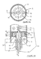
- the damper means consists of a piston and cylinder arrangement, illustrated generally at 1, and including a cylinder 3 and a piston and piston rod assembly 5.
- the piston and piston rod assembly 5 includes a piston head 7 and a piston rod 9.
- the piston head 7 divides the cylinder 3 into a first chamber 11 and a second chamber 13.
- the cylinder is filled with a damper-fluid, for example, oil, 14.
- the damper means also includes an auxiliary tank 15 including a free floating piston 17. Disposed below the free floating piston is a low pressure gas such as nitrogen 19. The upper chamber of the auxiliary tank is also filled with the same damper-fluid 14 as the cylinder 3.
- a flow channel 21 connects the cylinder to the auxiliary tank and permits the flow of the damper-fluid between the two.
- a variable low velocity restriction 23 and a variable high velocity restriction 25 in the flow channel. Restrictions 23 and 25 will be further described below.
- means 27 are provided in the piston and piston rod assembly 5 for permitting substantially unrestricted flow across the piston head from chamber 11 to chamber 13.
- variable low velocity restriction 23 comprises a reed valve 37 and a slidable adjustment block 39.
- Orifice adjustment means 47 adjusts the size of the orifice 45.
- the variable high velocity restriction 25 comprises a reed valve 41 and a slidable adjustment block 43.
- Reed valve 37 covers orifice 45 and an orifice adjustment means 47 adjusts the size of orifice 45.
- Reed valve 41 covers orifice 49.
- Reed valve 37 is relatively flexible, and reed valve 41 is relatively rigid. During the low velocity flow, flexible reed valve 37 will be moved, but rigid reed valve 41 will be moved very little if at all. Accordingly, the flow rate is determined substantially by the movement of reed valve 37.
- reed valve 37 will be substantially completely open so that the flow rate is controlled substantially by reed valve 41.
- Figure 5 illustrates the operation of the restriction means in the flow channel under different conditions.
- a e is the effective area, i.e., the effective area through which fluid can flow.
- ⁇ P is the pressure differential between the high and low pressure chambers.
- Dotted line 1 illustrates the effect of the bleed orifice 58. If the bleed orifice is completely closed by needle adjuster 60, then dotted line 1 would lie on the 0 line of the A e axis. As the needle 60 is pulled out more and more from the orifice 58, then a greater effective area opens through the orifice 58 so that, even under 0 change in pressure, there will still be an effective open area through which fluid can flow.
- Dotted line 2 shows the effect of more flexible reed valve 37.
- the straight horizontal part of dotted line 2 reflects the fact that there is a maximum effective area over the reed, i.e., when the reed is completely out of the way of its orifice, then increasing the pressure will not increase the effective area of the orifice.
- the maximum effective area is adjusted by needle valve 47 in much the same way that needle valve 60 affects the bleed orifice effective area.
- Dotted line 3 illustrates the effect of rigid reed valve 41. As can be seen, it takes a relatively large increase in pressure to provide even a small increase in effective area.
- Solid line 4 is a composite of the three dotted lines and shows the complete action of the restriction means in the flow channels. Briefly, at first, small increases in pressure will bring about large increases in effective area. After the break point, even a large increase in pressure will bring about only a small increase in effective area.
- a third reed valve would be supplied.
- the third reed valve would be even more rigid than rigid reed valve 41.
- the effect of the further reed valve would be as illustrated by line 101 in Figure 5A. That is, it will take an even greater increase in pressure to bring about a small increase in effective area.
- opening 51 in enclosure 35 is in communication with the auxiliary tank 15, while opening 53 in enclosure 35 is in communication with the cylinder 3.
- the means 29 for permitting substantially unrestricted flow through the flow channel comprises a one way valve 54.
- the one way valve 54 will be completely closed and will therefore not affect operation.
- one way valve 54 will be completely open to permit substantially unrestricted flow through opening 55 and thereby the channel 21.
- the arrangement also includes a bleed orifice 58 and a needle adjuster 60 for the orifice 58. By opening the bleed orifice 58, flow through can be increased during the compression stroke.
- variable low velocity restriction 31 in the piston and piston rod assembly comprises a hollow piston rod 59, concentric with piston head 7, and attached by means 57, to the piston head 7. Opening 61 extends through a wall of the piston rod 59.
- Restriction 31 further includes an inner cylinder 65, concentric with piston rod 59, and slidable up and down within the piston rod 59. By sliding the cylinder 65 up and down, the size of opening 61 is decreased and increased, to thereby vary restriction 31.
- a central opening 67 in piston head 7 permits the passage of fluid from chamber 13 through opening 61 through opening 67 into chamber 11 during the extension strokes.
- the variable high velocity restriction 33 comprises two openings 69 extending through the piston head 7.
- Rectangular plate 71 mounts two protrusions 72, each one of the protrusions being aligned with and being extendable through a respective opening 69.
- Control rod 75 extends through the central opening 67 and includes a cap 77. Disposed between the cap 77 and the rectangular plate 71 is a spring 79. The spring forces the plate 71 against the top surface 80 of the piston 7. The tension of the spring 79 is adjustable by the control rod 75. When the force of the fluid exceeds the force of the spring, the plate 71 will be forced upwardly and the protrusions 72 will be substantially out of their respective openings 69. This condition is referred to as blow-off and the entire valve is referred to as a blow-off valve.
- the blow-off point is, as above-mentioned, adjustable by adjustment of the rod 75.
- variable high velocity restriction 33 is illustrated.
- a e is the effective area and ⁇ P is the change in pressure.
- Line 2 has opening 61 only partially opened and includes a higher preload on the spring 79. Accordingly, it takes a larger pressure to begin moving plate 71 upwardly.
- the means 27 for permitting substantially unrestricted flow across the piston head comprises a series of holes or slots concentric around the piston with openings 81 and a covering flap valve 83.
- valve 83 will be forced away from opening 81 to permit substantially unrestricted flow across the valve.
- valve 83 will completely cover opening 81 so that it has no effect during the extension stroke.
- the novel damper means comprises a wide range of adjustment, and it will be obvious to one skilled in the art that all of the adjusting mechanisms can be made to be accessed externally. More consistent temperature distribution through the fluid is brought about by the remote location of the compression damping adjuster means relative to the extension adjuster means, and the reasons for reduction of possibility of cavitation have been discussed above. Accordingly, all of the objectives of the invention have been met.
Landscapes
- Engineering & Computer Science (AREA)
- General Engineering & Computer Science (AREA)
- Mechanical Engineering (AREA)
- Fluid-Damping Devices (AREA)
Applications Claiming Priority (2)
| Application Number | Priority Date | Filing Date | Title |
|---|---|---|---|
| US07/203,315 US4872537A (en) | 1988-06-06 | 1988-06-06 | Adjustable damper means for shock absorber |
| US203315 | 1988-06-06 |
Publications (2)
| Publication Number | Publication Date |
|---|---|
| EP0346040A2 true EP0346040A2 (de) | 1989-12-13 |
| EP0346040A3 EP0346040A3 (de) | 1990-09-19 |
Family
ID=22753447
Family Applications (1)
| Application Number | Title | Priority Date | Filing Date |
|---|---|---|---|
| EP19890305642 Withdrawn EP0346040A3 (de) | 1988-06-06 | 1989-06-05 | Regelbare Dämpfungsvorrichtung für Stossdämpfer |
Country Status (3)
| Country | Link |
|---|---|
| US (1) | US4872537A (de) |
| EP (1) | EP0346040A3 (de) |
| JP (1) | JPH0257739A (de) |
Cited By (5)
| Publication number | Priority date | Publication date | Assignee | Title |
|---|---|---|---|---|
| EP0662570A1 (de) * | 1994-01-11 | 1995-07-12 | Hks Co., Ltd. | Vorrichtung zum Einstellen der Dämpfungskraft von Dämpfern |
| FR2721670A1 (fr) * | 1994-06-24 | 1995-12-29 | Fichtel & Sachs Ag | Dispositif destiné à l'amortissement de systèmes élastiques de suspension de roues. |
| EP0740086A1 (de) * | 1995-04-27 | 1996-10-30 | Automobiles Peugeot | Einrichtung zur Dämpfung durch Flüssigkeitsschichtung und Kraftfahrzeugaufhängungssystem mit einer solchen Dämpfungseinrichtung |
| FR2776731A1 (fr) * | 1998-03-31 | 1999-10-01 | Donerre Amortisseur | Dispositif de reglage d'amortisseur a huile |
| EP1577580A3 (de) * | 2004-03-20 | 2006-05-31 | Krauss-Maffei Wegmann GmbH & Co. KG | Hydropneumatisches Federelement für Fahzeuge, insbesondere Kettenfahrzeuge, sowie Laufradaufhängung an einem Kettenfahrzeug mit einem derartigen Federelement |
Families Citing this family (21)
| Publication number | Priority date | Publication date | Assignee | Title |
|---|---|---|---|---|
| DE3827255C2 (de) * | 1988-08-11 | 1999-05-27 | Teves Gmbh Alfred | Regelbarer hydraulischer Schwingungsdämpfer für Kraftfahrzeuge |
| US6053486A (en) * | 1998-03-16 | 2000-04-25 | Suspa, Incorporated | Damping cylinder |
| US6267400B1 (en) | 1999-04-06 | 2001-07-31 | Specialized Bicycle Components, Inc. | Bicycle damping enhancement system |
| US6254067B1 (en) * | 1999-08-02 | 2001-07-03 | Giant Manufacturing Co., Ltd. | Fluid regulating device for use with a hydraulic cylinder to obtain a variable shock absorbing effect |
| US6460664B1 (en) | 2000-05-22 | 2002-10-08 | Tenneco Automotive Inc. | Independently tunable variable bleed orifice |
| AU2003208002A1 (en) * | 2003-01-31 | 2004-08-23 | Arvin Technologies | Integrated damping adjustment valve |
| DE102004026043B3 (de) * | 2004-05-27 | 2005-12-15 | Zf Friedrichshafen Ag | Drehschwingungsdämpfer |
| JP4911496B2 (ja) * | 2006-06-14 | 2012-04-04 | 下西技研工業株式会社 | 原稿圧着板の開閉装置 |
| US8616351B2 (en) | 2009-10-06 | 2013-12-31 | Tenneco Automotive Operating Company Inc. | Damper with digital valve |
| US9884533B2 (en) | 2013-02-28 | 2018-02-06 | Tenneco Automotive Operating Company Inc. | Autonomous control damper |
| WO2014134500A1 (en) | 2013-02-28 | 2014-09-04 | Tenneco Automotive Operating Company Inc. | Damper with integrated electronics |
| US9217483B2 (en) | 2013-02-28 | 2015-12-22 | Tenneco Automotive Operating Company Inc. | Valve switching controls for adjustable damper |
| US9879746B2 (en) | 2013-03-15 | 2018-01-30 | Tenneco Automotive Operating Company Inc. | Rod guide system and method with multiple solenoid valve cartridges and multiple pressure regulated valve assemblies |
| US9163691B2 (en) | 2013-03-15 | 2015-10-20 | Tenneco Automotive Operating Company Inc. | Rod guide arrangement for electronically controlled valve applications |
| US9879748B2 (en) | 2013-03-15 | 2018-01-30 | Tenneco Automotive Operating Company Inc. | Two position valve with face seal and pressure relief port |
| EP2971847A4 (de) | 2013-03-15 | 2016-12-21 | Tenneco Automotive Operating Co Inc | Stangenführungsanordnung mit mehrteiliger ventilanordnung |
| JP6408818B2 (ja) * | 2014-07-23 | 2018-10-17 | Kyb株式会社 | ピストンの製造方法 |
| JP6793296B2 (ja) | 2015-07-16 | 2020-12-02 | パナソニックIpマネジメント株式会社 | グラファイトプレート及びその製造方法 |
| US10479160B2 (en) | 2017-06-06 | 2019-11-19 | Tenneco Automotive Operating Company Inc. | Damper with printed circuit board carrier |
| US10588233B2 (en) | 2017-06-06 | 2020-03-10 | Tenneco Automotive Operating Company Inc. | Damper with printed circuit board carrier |
| CN108869622B (zh) * | 2018-07-24 | 2023-05-23 | 广东机电职业技术学院 | 一种柱塞式缓冲装置 |
Family Cites Families (22)
| Publication number | Priority date | Publication date | Assignee | Title |
|---|---|---|---|---|
| DE636841C (de) * | 1934-02-23 | 1937-01-30 | Ernst Wagner Appbau | Fluessigkeitsbremse, insbesondere fuer Hubwagen |
| DE1086567B (de) * | 1953-12-18 | 1960-08-04 | Willy Honnef | Hydraulischer Teleskopstossdaempfer fuer Kraftfahrzeuge mit im Kolben fuer beide Bewegungs-richtungen vorgesehenen federbelasteten Ventilen |
| DE1736883U (de) * | 1956-11-02 | 1956-12-27 | Gabriel Bloch | Stossdaempfer fuer kraftfahrzeuge u. dgl., insbesondere hydraulische stossdaempfer. |
| US4010829A (en) * | 1974-09-30 | 1977-03-08 | Yamaha, Hatsudoki Kabushiki Kaisha | Hydraulic shock absorber |
| US4153237A (en) * | 1976-11-01 | 1979-05-08 | Supalla Steven A | Hydrapneumatic suspension unit and valving structure |
| US4159106A (en) * | 1977-11-10 | 1979-06-26 | Nyman Bengt E | Vehicular suspension unit |
| US4159756A (en) * | 1978-01-17 | 1979-07-03 | Kayaba K.K. | Adjusting device for damping force of rear shock-absorbers of motorcycles |
| FR2415752A1 (fr) * | 1978-01-25 | 1979-08-24 | Sirven Jacques | Amortisseur hydraulique de suspension de vehicule |
| JPS54120375A (en) * | 1978-03-10 | 1979-09-18 | Showa Mfg Co Ltd | Oil pressure shock absorber |
| DE2855561A1 (de) * | 1978-12-22 | 1980-07-10 | Fichtel & Sachs Ag | Federbein oder stossdaempfer fuer fahrzeuge mit druckanschlag |
| JPS573144U (de) * | 1980-06-06 | 1982-01-08 | ||
| CA1152116A (en) * | 1980-07-10 | 1983-08-16 | Showa Manufacturing Co., Ltd. | Hydraulic shock absorber |
| DE3036079A1 (de) * | 1980-09-25 | 1982-05-06 | Volkswagenwerk Ag, 3180 Wolfsburg | Hydropneumatischer pralldaempfer |
| JPS58116841U (ja) * | 1982-02-01 | 1983-08-09 | カヤバ工業株式会社 | 複筒型油圧緩衝器の減衰力調整装置 |
| ES533297A0 (es) * | 1983-06-29 | 1985-03-01 | Boge Gmbh | Amortiguador hidraulico regulable |
| GB2149055B (en) * | 1983-09-26 | 1987-11-04 | Nhk Spring Co Ltd | Vehicle suspension unit with damping & spring rate adjustable |
| US4542768A (en) * | 1984-03-12 | 1985-09-24 | Rotron, Inc. | Pressure relief valve |
| DE3446133A1 (de) * | 1984-12-18 | 1986-06-19 | Fichtel & Sachs Ag, 8720 Schweinfurt | Schwingungsdaempfer mit veraenderbarer daempfkraft |
| DE3523628A1 (de) * | 1985-07-02 | 1987-01-15 | Bayerische Motoren Werke Ag | Ventilsystem fuer steuerbare, hydraulische schwingungsdaempfer |
| DE3532293C2 (de) * | 1985-09-11 | 1994-09-22 | Fichtel & Sachs Ag | Schwingungsdämpfer mit verstellbarer Dämpfkraft |
| NL8600211A (nl) * | 1986-01-30 | 1987-08-17 | White Power Prod Bv | Hydraulische schokdemper. |
| FR2618507B1 (fr) * | 1987-07-21 | 1993-12-03 | Sirven Jacques | Amortisseur hydraulique muni de moyens permettant de faire varier les caracteristiques de fonctionnement |
-
1988
- 1988-06-06 US US07/203,315 patent/US4872537A/en not_active Expired - Fee Related
-
1989
- 1989-06-05 EP EP19890305642 patent/EP0346040A3/de not_active Withdrawn
- 1989-06-06 JP JP1143945A patent/JPH0257739A/ja active Pending
Cited By (11)
| Publication number | Priority date | Publication date | Assignee | Title |
|---|---|---|---|---|
| EP0662570A1 (de) * | 1994-01-11 | 1995-07-12 | Hks Co., Ltd. | Vorrichtung zum Einstellen der Dämpfungskraft von Dämpfern |
| US5507371A (en) * | 1994-01-11 | 1996-04-16 | Hks Co., Ltd. | Damping force adjusting device for dampers |
| FR2721670A1 (fr) * | 1994-06-24 | 1995-12-29 | Fichtel & Sachs Ag | Dispositif destiné à l'amortissement de systèmes élastiques de suspension de roues. |
| US5833037A (en) * | 1994-06-24 | 1998-11-10 | Fichtel & Sachs Ag | Vibration damper or shock absorber having apparatus for damping spring-mounted wheel suspension systems |
| ES2123382A1 (es) * | 1994-06-24 | 1999-01-01 | Fichtel & Sachs Ag | Dispositivo para la amortiguacion de sistemas elasticos de suspension de rueda. |
| EP0740086A1 (de) * | 1995-04-27 | 1996-10-30 | Automobiles Peugeot | Einrichtung zur Dämpfung durch Flüssigkeitsschichtung und Kraftfahrzeugaufhängungssystem mit einer solchen Dämpfungseinrichtung |
| FR2733564A1 (fr) * | 1995-04-27 | 1996-10-31 | Peugeot | Agencement d'amortissement par laminage d'un fluide et systeme de suspension, notamment de vehicule automobile, equipe d'un tel agencement d'amortissement |
| US5842688A (en) * | 1995-04-27 | 1998-12-01 | Automobiles Peugeot-Automobiles Citroen | Arrangement for damping through wire-drawing of a fluid and suspension system in particular of an automotive vehicle fitted with such a damping arrangement |
| FR2776731A1 (fr) * | 1998-03-31 | 1999-10-01 | Donerre Amortisseur | Dispositif de reglage d'amortisseur a huile |
| US6334517B1 (en) | 1998-03-31 | 2002-01-01 | Amortisseur Donerre | Adjustment device for a hydraulic shock absorber |
| EP1577580A3 (de) * | 2004-03-20 | 2006-05-31 | Krauss-Maffei Wegmann GmbH & Co. KG | Hydropneumatisches Federelement für Fahzeuge, insbesondere Kettenfahrzeuge, sowie Laufradaufhängung an einem Kettenfahrzeug mit einem derartigen Federelement |
Also Published As
| Publication number | Publication date |
|---|---|
| US4872537A (en) | 1989-10-10 |
| JPH0257739A (ja) | 1990-02-27 |
| EP0346040A3 (de) | 1990-09-19 |
Similar Documents
| Publication | Publication Date | Title |
|---|---|---|
| EP0346040A2 (de) | Regelbare Dämpfungsvorrichtung für Stossdämpfer | |
| US4844428A (en) | Air spring assembly | |
| GB2164417A (en) | An adjustable hydraulic damper | |
| US20200318707A1 (en) | Vehicle suspension damper | |
| US12031604B2 (en) | Vibration damper having a two-stage restricted damping force control | |
| US20100109277A1 (en) | Adjustable Monotube Shock Absorber | |
| EP1588072B1 (de) | Ventil mit integrierter dämpfungseinstellung | |
| JPH06147252A (ja) | 油圧緩衝器 | |
| GB2222227A (en) | Damping force adjustable hydraulic shock absorber | |
| JPS60260731A (ja) | 調整可能な油圧式シヨツクアブソ−バ | |
| JPH03125044A (ja) | 緩衝機構 | |
| JP2002188674A (ja) | 速度依存の緩衝性を有するピストン−シリンダ装置 | |
| GB2327250A (en) | Adjustable vibration damper | |
| US5873437A (en) | Shock absorber | |
| WO1996008950A3 (en) | Continuously variable twin-tube shock damper | |
| US3351160A (en) | Remotely controlled, adjustable valve means for shock absorbers | |
| RU2020320C1 (ru) | Амортизатор с регулируемой силой гидродемпфирования | |
| DE60302304T2 (de) | Selbstnivellierender Fahrzeugradaufhängungsdämpfer | |
| US20070144848A1 (en) | Hydraulic damper for vehicle | |
| DE3434659C2 (de) | ||
| JP4048507B2 (ja) | 減衰力調整式油圧緩衝器 | |
| US4232767A (en) | Arrangement for adjusting the damping force of a shock absorber | |
| JPS6227726Y2 (de) | ||
| JPH0154202B2 (de) | ||
| DE3434658C2 (de) |
Legal Events
| Date | Code | Title | Description |
|---|---|---|---|
| PUAI | Public reference made under article 153(3) epc to a published international application that has entered the european phase |
Free format text: ORIGINAL CODE: 0009012 |
|
| AK | Designated contracting states |
Kind code of ref document: A2 Designated state(s): DE FR GB IT NL SE |
|
| PUAL | Search report despatched |
Free format text: ORIGINAL CODE: 0009013 |
|
| AK | Designated contracting states |
Kind code of ref document: A3 Designated state(s): DE FR GB IT NL SE |
|
| STAA | Information on the status of an ep patent application or granted ep patent |
Free format text: STATUS: THE APPLICATION HAS BEEN WITHDRAWN |
|
| 18W | Application withdrawn |
Withdrawal date: 19910503 |