EP0346040A2 - Adjustable damper means for shock absorber - Google Patents
Adjustable damper means for shock absorber Download PDFInfo
- Publication number
- EP0346040A2 EP0346040A2 EP89305642A EP89305642A EP0346040A2 EP 0346040 A2 EP0346040 A2 EP 0346040A2 EP 89305642 A EP89305642 A EP 89305642A EP 89305642 A EP89305642 A EP 89305642A EP 0346040 A2 EP0346040 A2 EP 0346040A2
- Authority
- EP
- European Patent Office
- Prior art keywords
- damper
- piston
- opening
- fluid
- during
- Prior art date
- Legal status (The legal status is an assumption and is not a legal conclusion. Google has not performed a legal analysis and makes no representation as to the accuracy of the status listed.)
- Withdrawn
Links
Images


Classifications
-
- F—MECHANICAL ENGINEERING; LIGHTING; HEATING; WEAPONS; BLASTING
- F16—ENGINEERING ELEMENTS AND UNITS; GENERAL MEASURES FOR PRODUCING AND MAINTAINING EFFECTIVE FUNCTIONING OF MACHINES OR INSTALLATIONS; THERMAL INSULATION IN GENERAL
- F16F—SPRINGS; SHOCK-ABSORBERS; MEANS FOR DAMPING VIBRATION
- F16F9/00—Springs, vibration-dampers, shock-absorbers, or similarly-constructed movement-dampers using a fluid or the equivalent as damping medium
- F16F9/32—Details
- F16F9/44—Means on or in the damper for manual or non-automatic adjustment; such means combined with temperature correction
-
- F—MECHANICAL ENGINEERING; LIGHTING; HEATING; WEAPONS; BLASTING
- F16—ENGINEERING ELEMENTS AND UNITS; GENERAL MEASURES FOR PRODUCING AND MAINTAINING EFFECTIVE FUNCTIONING OF MACHINES OR INSTALLATIONS; THERMAL INSULATION IN GENERAL
- F16F—SPRINGS; SHOCK-ABSORBERS; MEANS FOR DAMPING VIBRATION
- F16F9/00—Springs, vibration-dampers, shock-absorbers, or similarly-constructed movement-dampers using a fluid or the equivalent as damping medium
- F16F9/32—Details
- F16F9/50—Special means providing automatic damping adjustment, i.e. self-adjustment of damping by particular sliding movements of a valve element, other than flexions or displacement of valve discs; Special means providing self-adjustment of spring characteristics
- F16F9/516—Special means providing automatic damping adjustment, i.e. self-adjustment of damping by particular sliding movements of a valve element, other than flexions or displacement of valve discs; Special means providing self-adjustment of spring characteristics resulting in the damping effects during contraction being different from the damping effects during extension, i.e. responsive to the direction of movement
-
- Y—GENERAL TAGGING OF NEW TECHNOLOGICAL DEVELOPMENTS; GENERAL TAGGING OF CROSS-SECTIONAL TECHNOLOGIES SPANNING OVER SEVERAL SECTIONS OF THE IPC; TECHNICAL SUBJECTS COVERED BY FORMER USPC CROSS-REFERENCE ART COLLECTIONS [XRACs] AND DIGESTS
- Y10—TECHNICAL SUBJECTS COVERED BY FORMER USPC
- Y10T—TECHNICAL SUBJECTS COVERED BY FORMER US CLASSIFICATION
- Y10T137/00—Fluid handling
- Y10T137/7722—Line condition change responsive valves
- Y10T137/7837—Direct response valves [i.e., check valve type]
- Y10T137/7879—Resilient material valve
- Y10T137/7888—With valve member flexing about securement
- Y10T137/7891—Flap or reed
- Y10T137/7892—With stop
Definitions
- the invention relates to a damper means for a shock absorber which damper means comprises a damper-fluid filled piston and cylinder arrangement, an auxiliary tank, and a flow channel between the two. More specifically, the invention relates to such a damper means including variable high damper-fluid flow speed restriction means and variable low damper-fluid flow speed restriction means in the flow channel, and a variable high damper-fluid flow speed restriction means and a variable low damper-fluid flow speed restriction means in the piston and cylinder arrangement.
- damper means comprising oil-filled or damper-fluid filled piston and cylinder arrangements with auxiliary tanks as illustrated in, for example, United States Patent 4,546,959, Tanno, October 15, 1985, United States Patent 4,706,787, Wossner, November 17, 1987, and United States Patent 4,159,106, Nyman, June 26, 1979.
- the Tanno patent teaches the use of a variable restriction in the flow channel between the piston and cylinder arrangement and the auxiliary tank, but it is a single variable restriction and therefore has a limited range of adjustment.
- Tanno teaches a fixed restriction and a possibly variable restriction associated with the piston and cylinder arrangement.
- the Wossner patent also teaches a damper arrangement of the same general class.
- the variable restrictions in the piston and cylinder arrangement of Wossner is disposed in serial arrangement, and Wossner does not teach any restrictions between the piston and cylinder arrangement and the auxiliary tank.
- Nyman teaches a single variable restriction in the flow channel, and the possibility of a single variable restriction associated with the piston and cylinder arrangement.
- an adjustable damper means for a shock absorber which comprises a piston and cylinder arrangement comprising a cylinder, and a piston and piston rod assembly slidably mounted in the cylinder and dividing the cylinder into a first chamber and a second chamber, the cylinder being filled with a damper-fluid.
- the damper means also includes an auxiliary tank, and a flow channel permits flow of the damper-fluid between the cylinder and the auxiliary tank.
- the damper means also includes a first restriction means associated with the piston and piston rod assembly and substantially controlling the low velocity flow of the damper-fluid during the extenstion strokes, and a second restriction means associatd with the piston and piston rod assembly substantially controlling the high velocity flow of the damper-fluid during the extension strokes.
- a third restriction means in the flow channel substantially controls the low velocity flow of the damper-fluid during the compression strokes, and a fourth restriction means in the flow channel substantially controls the high velocity flow of the damper-fluid during the compression strokes.
- the damper means consists of a piston and cylinder arrangement, illustrated generally at 1, and including a cylinder 3 and a piston and piston rod assembly 5.
- the piston and piston rod assembly 5 includes a piston head 7 and a piston rod 9.
- the piston head 7 divides the cylinder 3 into a first chamber 11 and a second chamber 13.
- the cylinder is filled with a damper-fluid, for example, oil, 14.
- the damper means also includes an auxiliary tank 15 including a free floating piston 17. Disposed below the free floating piston is a low pressure gas such as nitrogen 19. The upper chamber of the auxiliary tank is also filled with the same damper-fluid 14 as the cylinder 3.
- a flow channel 21 connects the cylinder to the auxiliary tank and permits the flow of the damper-fluid between the two.
- a variable low velocity restriction 23 and a variable high velocity restriction 25 in the flow channel. Restrictions 23 and 25 will be further described below.
- means 27 are provided in the piston and piston rod assembly 5 for permitting substantially unrestricted flow across the piston head from chamber 11 to chamber 13.
- variable low velocity restriction 23 comprises a reed valve 37 and a slidable adjustment block 39.
- Orifice adjustment means 47 adjusts the size of the orifice 45.
- the variable high velocity restriction 25 comprises a reed valve 41 and a slidable adjustment block 43.
- Reed valve 37 covers orifice 45 and an orifice adjustment means 47 adjusts the size of orifice 45.
- Reed valve 41 covers orifice 49.
- Reed valve 37 is relatively flexible, and reed valve 41 is relatively rigid. During the low velocity flow, flexible reed valve 37 will be moved, but rigid reed valve 41 will be moved very little if at all. Accordingly, the flow rate is determined substantially by the movement of reed valve 37.
- reed valve 37 will be substantially completely open so that the flow rate is controlled substantially by reed valve 41.
- Figure 5 illustrates the operation of the restriction means in the flow channel under different conditions.
- a e is the effective area, i.e., the effective area through which fluid can flow.
- ⁇ P is the pressure differential between the high and low pressure chambers.
- Dotted line 1 illustrates the effect of the bleed orifice 58. If the bleed orifice is completely closed by needle adjuster 60, then dotted line 1 would lie on the 0 line of the A e axis. As the needle 60 is pulled out more and more from the orifice 58, then a greater effective area opens through the orifice 58 so that, even under 0 change in pressure, there will still be an effective open area through which fluid can flow.
- Dotted line 2 shows the effect of more flexible reed valve 37.
- the straight horizontal part of dotted line 2 reflects the fact that there is a maximum effective area over the reed, i.e., when the reed is completely out of the way of its orifice, then increasing the pressure will not increase the effective area of the orifice.
- the maximum effective area is adjusted by needle valve 47 in much the same way that needle valve 60 affects the bleed orifice effective area.
- Dotted line 3 illustrates the effect of rigid reed valve 41. As can be seen, it takes a relatively large increase in pressure to provide even a small increase in effective area.
- Solid line 4 is a composite of the three dotted lines and shows the complete action of the restriction means in the flow channels. Briefly, at first, small increases in pressure will bring about large increases in effective area. After the break point, even a large increase in pressure will bring about only a small increase in effective area.
- a third reed valve would be supplied.
- the third reed valve would be even more rigid than rigid reed valve 41.
- the effect of the further reed valve would be as illustrated by line 101 in Figure 5A. That is, it will take an even greater increase in pressure to bring about a small increase in effective area.
- opening 51 in enclosure 35 is in communication with the auxiliary tank 15, while opening 53 in enclosure 35 is in communication with the cylinder 3.
- the means 29 for permitting substantially unrestricted flow through the flow channel comprises a one way valve 54.
- the one way valve 54 will be completely closed and will therefore not affect operation.
- one way valve 54 will be completely open to permit substantially unrestricted flow through opening 55 and thereby the channel 21.
- the arrangement also includes a bleed orifice 58 and a needle adjuster 60 for the orifice 58. By opening the bleed orifice 58, flow through can be increased during the compression stroke.
- variable low velocity restriction 31 in the piston and piston rod assembly comprises a hollow piston rod 59, concentric with piston head 7, and attached by means 57, to the piston head 7. Opening 61 extends through a wall of the piston rod 59.
- Restriction 31 further includes an inner cylinder 65, concentric with piston rod 59, and slidable up and down within the piston rod 59. By sliding the cylinder 65 up and down, the size of opening 61 is decreased and increased, to thereby vary restriction 31.
- a central opening 67 in piston head 7 permits the passage of fluid from chamber 13 through opening 61 through opening 67 into chamber 11 during the extension strokes.
- the variable high velocity restriction 33 comprises two openings 69 extending through the piston head 7.
- Rectangular plate 71 mounts two protrusions 72, each one of the protrusions being aligned with and being extendable through a respective opening 69.
- Control rod 75 extends through the central opening 67 and includes a cap 77. Disposed between the cap 77 and the rectangular plate 71 is a spring 79. The spring forces the plate 71 against the top surface 80 of the piston 7. The tension of the spring 79 is adjustable by the control rod 75. When the force of the fluid exceeds the force of the spring, the plate 71 will be forced upwardly and the protrusions 72 will be substantially out of their respective openings 69. This condition is referred to as blow-off and the entire valve is referred to as a blow-off valve.
- the blow-off point is, as above-mentioned, adjustable by adjustment of the rod 75.
- variable high velocity restriction 33 is illustrated.
- a e is the effective area and ⁇ P is the change in pressure.
- Line 2 has opening 61 only partially opened and includes a higher preload on the spring 79. Accordingly, it takes a larger pressure to begin moving plate 71 upwardly.
- the means 27 for permitting substantially unrestricted flow across the piston head comprises a series of holes or slots concentric around the piston with openings 81 and a covering flap valve 83.
- valve 83 will be forced away from opening 81 to permit substantially unrestricted flow across the valve.
- valve 83 will completely cover opening 81 so that it has no effect during the extension stroke.
- the novel damper means comprises a wide range of adjustment, and it will be obvious to one skilled in the art that all of the adjusting mechanisms can be made to be accessed externally. More consistent temperature distribution through the fluid is brought about by the remote location of the compression damping adjuster means relative to the extension adjuster means, and the reasons for reduction of possibility of cavitation have been discussed above. Accordingly, all of the objectives of the invention have been met.
Landscapes
- Engineering & Computer Science (AREA)
- General Engineering & Computer Science (AREA)
- Mechanical Engineering (AREA)
- Fluid-Damping Devices (AREA)
Abstract
A piston and cylinder arrangement (1), which includes a piston and piston rod assembly (3) and which is filled with a damper-fluid, is attached to an auxiliary tank (15) by a flow channel. A first restriction in the piston and piston rod assembly substantially controls the low velocity flow of the damper fluid during extension strokes and a second restriction in the piston and piston rod assembly substantially controls high velocity flow of the damper fluid during the extension strokes. A third restriction (23) in the flow channel substantially controls the low velocity flow of the damper-fluid during compression strokes, and a fourth restriction (25) in the flow channel substantially controls the high velocity flow of the damper-fluid during the compression strokes. Substantially unrestricted flow of the damper-fluid through the piston and piston rod assembly is permitted during the compression strokes, and substantially unrestricted flow of the damper-fluid through the flow channel is permitted during extension strokes.
Description
- The invention relates to a damper means for a shock absorber which damper means comprises a damper-fluid filled piston and cylinder arrangement, an auxiliary tank, and a flow channel between the two. More specifically, the invention relates to such a damper means including variable high damper-fluid flow speed restriction means and variable low damper-fluid flow speed restriction means in the flow channel, and a variable high damper-fluid flow speed restriction means and a variable low damper-fluid flow speed restriction means in the piston and cylinder arrangement.
- Known in the art are damper means comprising oil-filled or damper-fluid filled piston and cylinder arrangements with auxiliary tanks as illustrated in, for example, United States Patent 4,546,959, Tanno, October 15, 1985, United States Patent 4,706,787, Wossner, November 17, 1987, and United States Patent 4,159,106, Nyman, June 26, 1979. The Tanno patent teaches the use of a variable restriction in the flow channel between the piston and cylinder arrangement and the auxiliary tank, but it is a single variable restriction and therefore has a limited range of adjustment. In addition, Tanno teaches a fixed restriction and a possibly variable restriction associated with the piston and cylinder arrangement.
- The Wossner patent also teaches a damper arrangement of the same general class. However, the variable restrictions in the piston and cylinder arrangement of Wossner is disposed in serial arrangement, and Wossner does not teach any restrictions between the piston and cylinder arrangement and the auxiliary tank.
- Nyman teaches a single variable restriction in the flow channel, and the possibility of a single variable restriction associated with the piston and cylinder arrangement.
- United States Patent 4,442,926, Muto, April 17, 1984, also teaches a damper comprising a damper-fluid filled piston and cylinder arrangement, and an auxiliary tank. Variable restrictions, for the compression and extension strokes, are included in the piston and cylinder arrangements.
- The problems with the above available dampers, and others not identified herein, is that they have a limited range of adjustment and, typically, except for Tanno and Wossner, the adjustments cannot be made externally, so that they comprise in fact factory, rather than user, adjustments.
- In addition, and especially in dampers as in the Tanno patent, there is a danger of cavitation, the so-called meter-out effect, behind the piston (on the rod side thereof) during the compression stroke.
- It is therefore an object of the invention to provide a damper means for a shock absorber which overcomes the above-noted disadvantages.
- It is a more specific object of the invention to provide an adjustable damper means with a wide range of adjustments which can be made externally.
- It is a further object of the invention to provide a damper means which avoids cavitation.
- In accordance with the invention there is provided an adjustable damper means for a shock absorber which comprises a piston and cylinder arrangement comprising a cylinder, and a piston and piston rod assembly slidably mounted in the cylinder and dividing the cylinder into a first chamber and a second chamber, the cylinder being filled with a damper-fluid. The damper means also includes an auxiliary tank, and a flow channel permits flow of the damper-fluid between the cylinder and the auxiliary tank. During the compression strokes of the piston and piston rod assembly, the volume of the first chamber is decreased and the volume of the second chamber is increased, and during the extension strokes of the piston and piston cylinder arrangement, the volume of the first chamber is increased and the volume of the second chamber is decreased. The damper means also includes a first restriction means associated with the piston and piston rod assembly and substantially controlling the low velocity flow of the damper-fluid during the extenstion strokes, and a second restriction means associatd with the piston and piston rod assembly substantially controlling the high velocity flow of the damper-fluid during the extension strokes. A third restriction means in the flow channel substantially controls the low velocity flow of the damper-fluid during the compression strokes, and a fourth restriction means in the flow channel substantially controls the high velocity flow of the damper-fluid during the compression strokes.
- The invention will be better understood by an examination of the following description, together with the accompanying drawings, in which:
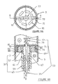
- FIGURE 1 is a schematic drawing of the damper means during the compression stroke;
- FIGURE 2 is a schematic drawing of the damper means during the extension stroke;
- FIGURE 3 illustrates the restriction means in the flow channel;
- FIGURE 4 is a section through IV-IV of Figure 3;
- FIGURE 5 is an effective area versus change in pressure graph of the restriction means of Figure 3;
- FIGURE 5A is a composite of the several curves in Figure 5;
- FIGURE 6A is a top view and FIGURE 6B is a plan view in section of the restriction means in the piston and piston rod assembly; and
- FIGURE 7 is an effective area versus change in pressure graph of the Figure 6 restriction means.
- Referring first to Figure 1, the damper means consists of a piston and cylinder arrangement, illustrated generally at 1, and including a
cylinder 3 and a piston andpiston rod assembly 5. The piston andpiston rod assembly 5 includes apiston head 7 and apiston rod 9. Thepiston head 7 divides thecylinder 3 into afirst chamber 11 and asecond chamber 13. The cylinder is filled with a damper-fluid, for example, oil, 14. - The damper means also includes an
auxiliary tank 15 including a freefloating piston 17. Disposed below the free floating piston is a low pressure gas such asnitrogen 19. The upper chamber of the auxiliary tank is also filled with the same damper-fluid 14 as thecylinder 3. - A
flow channel 21 connects the cylinder to the auxiliary tank and permits the flow of the damper-fluid between the two. During the compression stroke, there is a variablelow velocity restriction 23 and a variablehigh velocity restriction 25 in the flow channel.Restrictions - Again, in the compression stroke, means 27 are provided in the piston and
piston rod assembly 5 for permitting substantially unrestricted flow across the piston head fromchamber 11 tochamber 13. - As will be clear, during the compression stroke, when the piston and piston rod assembly move in the direction of the arrow U, the volume of the
upper chamber 11 is decreasing while the volume of thelower chamber 13 is increasing. - Because of the placement of the restriction during the compression stroke, a vacuum will not form on the bottom of the piston head (the rod side of the piston head) as there is substantially unrestricted flow across the piston head. Thus, cavitation is avoided.
- Referring now to Figure 2, wherein like numerals refer to like parts, it can be seen that during the extension stroke, when the piston and rod assembly move in the direction of the arrow E,
means 29 are provided inflow channel 21 to permit substantially unrestricted flow through the flow channel. A variablelow velocity restriction 31 is included in the piston head, and a variablehigh velocity restriction 33 is also included in the piston head. During the extension stroke, the oil inchamber 13 is at high pressure and the oil inchamber 11 is at low pressure. - Referring now to Figures 3 and 4, the restriction means in the flow channels are housed in an
enclosure 35. As can be seen, the variablelow velocity restriction 23 comprises areed valve 37 and aslidable adjustment block 39. Orifice adjustment means 47 adjusts the size of theorifice 45. - The variable
high velocity restriction 25 comprises areed valve 41 and aslidable adjustment block 43.Reed valve 37 coversorifice 45 and an orifice adjustment means 47 adjusts the size oforifice 45. Reedvalve 41 coversorifice 49. -
Reed valve 37 is relatively flexible, andreed valve 41 is relatively rigid. During the low velocity flow,flexible reed valve 37 will be moved, butrigid reed valve 41 will be moved very little if at all. Accordingly, the flow rate is determined substantially by the movement ofreed valve 37. - During high velocity flow,
reed valve 37 will be substantially completely open so that the flow rate is controlled substantially byreed valve 41. - Referring now to Figure 5, Figure 5 illustrates the operation of the restriction means in the flow channel under different conditions. Ae is the effective area, i.e., the effective area through which fluid can flow. Δ P is the pressure differential between the high and low pressure chambers.
- Dotted
line 1 illustrates the effect of thebleed orifice 58. If the bleed orifice is completely closed byneedle adjuster 60, then dottedline 1 would lie on the 0 line of the Ae axis. As theneedle 60 is pulled out more and more from theorifice 58, then a greater effective area opens through theorifice 58 so that, even under 0 change in pressure, there will still be an effective open area through which fluid can flow. - Dotted
line 2 shows the effect of moreflexible reed valve 37. The straight horizontal part ofdotted line 2 reflects the fact that there is a maximum effective area over the reed, i.e., when the reed is completely out of the way of its orifice, then increasing the pressure will not increase the effective area of the orifice. The maximum effective area is adjusted byneedle valve 47 in much the same way thatneedle valve 60 affects the bleed orifice effective area. -
Dotted line 3 illustrates the effect ofrigid reed valve 41. As can be seen, it takes a relatively large increase in pressure to provide even a small increase in effective area. -
Solid line 4 is a composite of the three dotted lines and shows the complete action of the restriction means in the flow channels. Briefly, at first, small increases in pressure will bring about large increases in effective area. After the break point, even a large increase in pressure will bring about only a small increase in effective area. - To provide even greater control, a third reed valve would be supplied. The third reed valve would be even more rigid than
rigid reed valve 41. The effect of the further reed valve would be as illustrated byline 101 in Figure 5A. That is, it will take an even greater increase in pressure to bring about a small increase in effective area. - Returning to Figures 3 and 4, opening 51 in
enclosure 35 is in communication with theauxiliary tank 15, while opening 53 inenclosure 35 is in communication with thecylinder 3. - The means 29 for permitting substantially unrestricted flow through the flow channel comprises a one
way valve 54. During the compression stroke, the oneway valve 54 will be completely closed and will therefore not affect operation. However, during the extension stroke, oneway valve 54 will be completely open to permit substantially unrestricted flow throughopening 55 and thereby thechannel 21. - The arrangement also includes a
bleed orifice 58 and aneedle adjuster 60 for theorifice 58. By opening thebleed orifice 58, flow through can be increased during the compression stroke. - Referring now to Figure 6, the variable
low velocity restriction 31 in the piston and piston rod assembly comprises ahollow piston rod 59, concentric withpiston head 7, and attached bymeans 57, to thepiston head 7.Opening 61 extends through a wall of thepiston rod 59. -
Restriction 31 further includes aninner cylinder 65, concentric withpiston rod 59, and slidable up and down within thepiston rod 59. By sliding thecylinder 65 up and down, the size ofopening 61 is decreased and increased, to thereby varyrestriction 31. - A
central opening 67 inpiston head 7 permits the passage of fluid fromchamber 13 throughopening 61 throughopening 67 intochamber 11 during the extension strokes. - The variable
high velocity restriction 33 comprises twoopenings 69 extending through thepiston head 7.Rectangular plate 71 mounts twoprotrusions 72, each one of the protrusions being aligned with and being extendable through arespective opening 69.Control rod 75 extends through thecentral opening 67 and includes acap 77. Disposed between thecap 77 and therectangular plate 71 is aspring 79. The spring forces theplate 71 against thetop surface 80 of thepiston 7. The tension of thespring 79 is adjustable by thecontrol rod 75. When the force of the fluid exceeds the force of the spring, theplate 71 will be forced upwardly and theprotrusions 72 will be substantially out of theirrespective openings 69. This condition is referred to as blow-off and the entire valve is referred to as a blow-off valve. The blow-off point is, as above-mentioned, adjustable by adjustment of therod 75. - Referring to Figure 7, the operation of the variable
high velocity restriction 33 is illustrated. Once again, Ae is the effective area and Δ P is the change in pressure. - In
line 1,cylinder 65 is moved downwardly so that opening 61 is completely open.Rod 75 is adjusted so that there is only a small preload on thespring 79. Thus, it takes only a relatively small amount of pressure to start lifting therectangular plate 71 upwardly. The horizontal line at the right indicates complete blow-off so that no further area can be opened. -
Line 2 hasopening 61 only partially opened and includes a higher preload on thespring 79. Accordingly, it takes a larger pressure to begin movingplate 71 upwardly. - The means 27 for permitting substantially unrestricted flow across the piston head comprises a series of holes or slots concentric around the piston with
openings 81 and acovering flap valve 83. During the compression stroke,valve 83 will be forced away from opening 81 to permit substantially unrestricted flow across the valve. During the extension stroke,valve 83 will completely coveropening 81 so that it has no effect during the extension stroke. - It can be quite easily seen that the novel damper means comprises a wide range of adjustment, and it will be obvious to one skilled in the art that all of the adjusting mechanisms can be made to be accessed externally. More consistent temperature distribution through the fluid is brought about by the remote location of the compression damping adjuster means relative to the extension adjuster means, and the reasons for reduction of possibility of cavitation have been discussed above. Accordingly, all of the objectives of the invention have been met.
- Although a particular embodiment has been described, this was for the purpose of illustrating, but not limiting, the invention. Various modifications, which will come readily to the mind of one skilled in the art, are within the scope of the invention as defined in the appended claims.
Claims (11)
1. Adjustable damper means for a shock absorber, comprising:
a piston and cylinder arrangement comprising a cylinder, and a piston and piston rod assembly slidably mounted in said cylinder and dividing said cylinder into a first chamber and a second chamber, said cylinder being filled with a damper-fluid;
an auxiliary tank;
a flow channel permitting flow of said damper-fluid between said cylinder and said auxiliary tank;
wherein, during a compression strokes of said piston and piston rod assembly, the volume of said first chamber is decreased and the volume of said second chamber is increased; and
during an extension strokes of said piston and piston cylinder arrangement, the volume of said first chamber is increased and the volume of said second chamber is decreased;
and including:
a first restriction means associated with said piston and piston rod assembly and substantially controlling the low velocity flow of said damper-fluid during said extenstion strokes, and a second restriction means associatd with said piston and piston rod assembly substantially controlling high velocity flow of said damper-fluid during said extension strokes; and
a third restriction means in said flow channel substantially controlling the low velocity flow of said damper-fluid during said compression strokes and a fourth restriction means in said flow channel substantially controlling the high velocity flow of said damper-fluid during said compression strokes.
2. A damper means as defined in claim 1 and further including first means permitting subtantially unrestricted flow of said damper-fluid through said piston and piston rod assembly during said compression strokes, and a second means permitting substantially unrestricted flow of said damper-fluid through said flow channel during said extension strokes.
3. A damper means as defined in claim 1 wherein said piston and piston rod assembly comprise a truncated cylindrical piston head having a top surface and a bottom surface, a central opening extending through said piston head, said piston rod comprising a hollow piston rod, an inner cylinder movably mounted in said hollow piston rod, said inner cylinder being concentric with said piston head, an opening in the side wall of said hollow piston rod;
wherein, said first restriction means comprises said opening in said side wall, said first restriction being variable by the inner cylinder adjusting the size of said opening in said side wall.
wherein, said first restriction means comprises said opening in said side wall, said first restriction being variable by the inner cylinder adjusting the size of said opening in said side wall.
4. A damper means as defined in claim 1 wherein the second restriction means comprises a blow off valve.
5. A damper means as defined in claim 4 wherein said second restriction means comprises two openings extending through said piston head from the top surface to the bottom surface thereof;
a rectangular plate, comprising two protrusions, each protrusion being mounted to be aligned with and to extend into a respective opening;
said plate being mounted over the top surface of said piston head;
an adjustment rod extending through said central opening and including a cap at the top end thereof;
a spring between said cap and said plate, the tension of said spring being adjustable by said adjustment rod whereby said second restriction means is also variable.
6. A damper means as defined in claim 1 wherein said means permitting substantially unrestricted flow of said damper-fluid through said piston and piston rod assembly during said compression strokes comprises a series of holes or slots opening around said piston head and extending through said piston head from the bottom surface to the top surface thereof; and
a flapper rod disposed adjacent said circular opening on the bottom surface of said piston head.
a flapper rod disposed adjacent said circular opening on the bottom surface of said piston head.
7. A damper means as defined in claim 1 wherein said third restriction means and said fourth restriction means and said second means permitting substantially unrestricted flow of said damper-fluid through said flow channel during said extension strokes comprises an enclosure disposed in said flow channel;
a first opening in said enclosure connected to said cylinder;
a second opening in said enclosure connected to said auxiliary tank.
a first opening in said enclosure connected to said cylinder;
a second opening in said enclosure connected to said auxiliary tank.
8. A damper means as defined in claim 7 wherein said third restriction means comprises:
a first orifice between said first opening and said second opening;
a first means for adjusting said first orifice;
a first reed disposed over said first orifice;
first means for adjusting the stiffness of said first reed.
a first orifice between said first opening and said second opening;
a first means for adjusting said first orifice;
a first reed disposed over said first orifice;
first means for adjusting the stiffness of said first reed.
9. A damper means as defined in claim 8 wherein said fourth restriction means comprises:
a second orifice between said first opening and said second opening;
a second means for adjusting said second orifice;
a second reed disposed over said second orifice;
second means for adjusting the stiffness of said second reed.
a second orifice between said first opening and said second opening;
a second means for adjusting said second orifice;
a second reed disposed over said second orifice;
second means for adjusting the stiffness of said second reed.
10. A damper means as defined in claim 9 wherein said first reed means is relatively flexible and wherein said second reed means is relatively rigid.
11. A damper means as defined in claim 10 wherein said second means permitting substantially unrestricted flow of said damper-fluid through said flow channel during said extension strokes comprises a one way valve between said first opening and said second opening and mounted such that said valve is fully open during said extension strokes and is fully closed during said compression strokes.
Applications Claiming Priority (2)
| Application Number | Priority Date | Filing Date | Title |
|---|---|---|---|
| US07/203,315 US4872537A (en) | 1988-06-06 | 1988-06-06 | Adjustable damper means for shock absorber |
| US203315 | 1988-06-06 |
Publications (2)
| Publication Number | Publication Date |
|---|---|
| EP0346040A2 true EP0346040A2 (en) | 1989-12-13 |
| EP0346040A3 EP0346040A3 (en) | 1990-09-19 |
Family
ID=22753447
Family Applications (1)
| Application Number | Title | Priority Date | Filing Date |
|---|---|---|---|
| EP19890305642 Withdrawn EP0346040A3 (en) | 1988-06-06 | 1989-06-05 | Adjustable damper means for shock absorber |
Country Status (3)
| Country | Link |
|---|---|
| US (1) | US4872537A (en) |
| EP (1) | EP0346040A3 (en) |
| JP (1) | JPH0257739A (en) |
Cited By (5)
| Publication number | Priority date | Publication date | Assignee | Title |
|---|---|---|---|---|
| EP0662570A1 (en) * | 1994-01-11 | 1995-07-12 | Hks Co., Ltd. | Damping force adjusting device for dampers |
| FR2721670A1 (en) * | 1994-06-24 | 1995-12-29 | Fichtel & Sachs Ag | Device for the damping of elastic wheel suspension systems. |
| EP0740086A1 (en) * | 1995-04-27 | 1996-10-30 | Automobiles Peugeot | Arrangement for damping by fluid lamination and motor vehicle suspension system equiped with such a damping arrangement |
| FR2776731A1 (en) * | 1998-03-31 | 1999-10-01 | Donerre Amortisseur | Oil damper control unit for external adjustment |
| EP1577580A3 (en) * | 2004-03-20 | 2006-05-31 | Krauss-Maffei Wegmann GmbH & Co. KG | Hydropneumatic spring for vehicle, especially tracked vehicle, and suspension unit for roll wheel on a tracked vehicle equipped with this spring |
Families Citing this family (21)
| Publication number | Priority date | Publication date | Assignee | Title |
|---|---|---|---|---|
| DE3827255C2 (en) * | 1988-08-11 | 1999-05-27 | Teves Gmbh Alfred | Adjustable hydraulic vibration damper for motor vehicles |
| US6053486A (en) * | 1998-03-16 | 2000-04-25 | Suspa, Incorporated | Damping cylinder |
| US6267400B1 (en) | 1999-04-06 | 2001-07-31 | Specialized Bicycle Components, Inc. | Bicycle damping enhancement system |
| US6254067B1 (en) * | 1999-08-02 | 2001-07-03 | Giant Manufacturing Co., Ltd. | Fluid regulating device for use with a hydraulic cylinder to obtain a variable shock absorbing effect |
| US6460664B1 (en) | 2000-05-22 | 2002-10-08 | Tenneco Automotive Inc. | Independently tunable variable bleed orifice |
| US7347307B2 (en) * | 2003-01-31 | 2008-03-25 | Arvin Technologies | Integrated damping adjustment valve |
| DE102004026043B3 (en) * | 2004-05-27 | 2005-12-15 | Zf Friedrichshafen Ag | torsional vibration dampers |
| JP4911496B2 (en) * | 2006-06-14 | 2012-04-04 | 下西技研工業株式会社 | Opening and closing device for original cover |
| US8616351B2 (en) | 2009-10-06 | 2013-12-31 | Tenneco Automotive Operating Company Inc. | Damper with digital valve |
| WO2014134500A1 (en) | 2013-02-28 | 2014-09-04 | Tenneco Automotive Operating Company Inc. | Damper with integrated electronics |
| US9217483B2 (en) | 2013-02-28 | 2015-12-22 | Tenneco Automotive Operating Company Inc. | Valve switching controls for adjustable damper |
| US9884533B2 (en) | 2013-02-28 | 2018-02-06 | Tenneco Automotive Operating Company Inc. | Autonomous control damper |
| US9163691B2 (en) | 2013-03-15 | 2015-10-20 | Tenneco Automotive Operating Company Inc. | Rod guide arrangement for electronically controlled valve applications |
| US9879746B2 (en) | 2013-03-15 | 2018-01-30 | Tenneco Automotive Operating Company Inc. | Rod guide system and method with multiple solenoid valve cartridges and multiple pressure regulated valve assemblies |
| US9879748B2 (en) | 2013-03-15 | 2018-01-30 | Tenneco Automotive Operating Company Inc. | Two position valve with face seal and pressure relief port |
| CN105308351B (en) | 2013-03-15 | 2017-08-15 | 坦尼科汽车操作有限公司 | Bar guide assembly with multi-piece type valve member |
| JP6408818B2 (en) * | 2014-07-23 | 2018-10-17 | Kyb株式会社 | Piston manufacturing method |
| JP6793296B2 (en) | 2015-07-16 | 2020-12-02 | パナソニックIpマネジメント株式会社 | Graphite plate and its manufacturing method |
| US10479160B2 (en) | 2017-06-06 | 2019-11-19 | Tenneco Automotive Operating Company Inc. | Damper with printed circuit board carrier |
| US10588233B2 (en) | 2017-06-06 | 2020-03-10 | Tenneco Automotive Operating Company Inc. | Damper with printed circuit board carrier |
| CN108869622B (en) * | 2018-07-24 | 2023-05-23 | 广东机电职业技术学院 | Plunger type buffer device |
Family Cites Families (22)
| Publication number | Priority date | Publication date | Assignee | Title |
|---|---|---|---|---|
| DE636841C (en) * | 1934-02-23 | 1937-01-30 | Ernst Wagner Appbau | Fluid brake, especially for lift trucks |
| DE1086567B (en) * | 1953-12-18 | 1960-08-04 | Willy Honnef | Hydraulic telescopic shock absorber for motor vehicles with spring-loaded valves provided in the piston for both directions of movement |
| DE1736883U (en) * | 1956-11-02 | 1956-12-27 | Gabriel Bloch | SHOCK ABSORBERS FOR MOTOR VEHICLES ETC., IN PARTICULAR HYDRAULIC SHOCK ABSORBERS. |
| US4010829A (en) * | 1974-09-30 | 1977-03-08 | Yamaha, Hatsudoki Kabushiki Kaisha | Hydraulic shock absorber |
| US4153237A (en) * | 1976-11-01 | 1979-05-08 | Supalla Steven A | Hydrapneumatic suspension unit and valving structure |
| US4159106A (en) * | 1977-11-10 | 1979-06-26 | Nyman Bengt E | Vehicular suspension unit |
| US4159756A (en) * | 1978-01-17 | 1979-07-03 | Kayaba K.K. | Adjusting device for damping force of rear shock-absorbers of motorcycles |
| FR2415752A1 (en) * | 1978-01-25 | 1979-08-24 | Sirven Jacques | VEHICLE SUSPENSION HYDRAULIC SHOCK ABSORBER |
| JPS54120375A (en) * | 1978-03-10 | 1979-09-18 | Showa Mfg Co Ltd | Oil pressure shock absorber |
| DE2855561A1 (en) * | 1978-12-22 | 1980-07-10 | Fichtel & Sachs Ag | SHOCK ABSORBER OR SHOCK ABSORBER FOR VEHICLES WITH PRESSURE STOP |
| JPS573144U (en) * | 1980-06-06 | 1982-01-08 | ||
| CA1152116A (en) * | 1980-07-10 | 1983-08-16 | Showa Manufacturing Co., Ltd. | Hydraulic shock absorber |
| DE3036079A1 (en) * | 1980-09-25 | 1982-05-06 | Volkswagenwerk Ag, 3180 Wolfsburg | Hydropneumatic tubular shock-absorber - has pins on piston protruding into fluid passages on return stroke forming valve |
| JPS58116841U (en) * | 1982-02-01 | 1983-08-09 | カヤバ工業株式会社 | Damping force adjustment device for dual-tube hydraulic shock absorber |
| ES8503803A1 (en) * | 1983-06-29 | 1985-03-01 | Boge Gmbh | Adjustable hydraulic damper apparatus |
| GB2149055B (en) * | 1983-09-26 | 1987-11-04 | Nhk Spring Co Ltd | Vehicle suspension unit with damping & spring rate adjustable |
| US4542768A (en) * | 1984-03-12 | 1985-09-24 | Rotron, Inc. | Pressure relief valve |
| DE3446133A1 (en) * | 1984-12-18 | 1986-06-19 | Fichtel & Sachs Ag, 8720 Schweinfurt | VIBRATION DAMPER WITH VARIABLE DAMPING FORCE |
| DE3523628A1 (en) * | 1985-07-02 | 1987-01-15 | Bayerische Motoren Werke Ag | VALVE SYSTEM FOR CONTROLLABLE, HYDRAULIC VIBRATION DAMPERS |
| DE3532293C2 (en) * | 1985-09-11 | 1994-09-22 | Fichtel & Sachs Ag | Vibration damper with adjustable damping force |
| NL8600211A (en) * | 1986-01-30 | 1987-08-17 | White Power Prod Bv | HYDRAULIC SHOCK ABSORBER. |
| FR2618507B1 (en) * | 1987-07-21 | 1993-12-03 | Sirven Jacques | HYDRAULIC SHOCK ABSORBER PROVIDED WITH MEANS FOR VARYING THE OPERATING CHARACTERISTICS |
-
1988
- 1988-06-06 US US07/203,315 patent/US4872537A/en not_active Expired - Fee Related
-
1989
- 1989-06-05 EP EP19890305642 patent/EP0346040A3/en not_active Withdrawn
- 1989-06-06 JP JP1143945A patent/JPH0257739A/en active Pending
Cited By (11)
| Publication number | Priority date | Publication date | Assignee | Title |
|---|---|---|---|---|
| EP0662570A1 (en) * | 1994-01-11 | 1995-07-12 | Hks Co., Ltd. | Damping force adjusting device for dampers |
| US5507371A (en) * | 1994-01-11 | 1996-04-16 | Hks Co., Ltd. | Damping force adjusting device for dampers |
| FR2721670A1 (en) * | 1994-06-24 | 1995-12-29 | Fichtel & Sachs Ag | Device for the damping of elastic wheel suspension systems. |
| US5833037A (en) * | 1994-06-24 | 1998-11-10 | Fichtel & Sachs Ag | Vibration damper or shock absorber having apparatus for damping spring-mounted wheel suspension systems |
| ES2123382A1 (en) * | 1994-06-24 | 1999-01-01 | Fichtel & Sachs Ag | Vibration damper or shock absorber having apparatus for damping spring-mounted wheel suspension systems |
| EP0740086A1 (en) * | 1995-04-27 | 1996-10-30 | Automobiles Peugeot | Arrangement for damping by fluid lamination and motor vehicle suspension system equiped with such a damping arrangement |
| FR2733564A1 (en) * | 1995-04-27 | 1996-10-31 | Peugeot | DAMPING ARRANGEMENT BY ROLLING A FLUID AND A SUSPENSION SYSTEM, IN PARTICULAR A MOTOR VEHICLE, EQUIPPED WITH SUCH A DAMPING ARRANGEMENT |
| US5842688A (en) * | 1995-04-27 | 1998-12-01 | Automobiles Peugeot-Automobiles Citroen | Arrangement for damping through wire-drawing of a fluid and suspension system in particular of an automotive vehicle fitted with such a damping arrangement |
| FR2776731A1 (en) * | 1998-03-31 | 1999-10-01 | Donerre Amortisseur | Oil damper control unit for external adjustment |
| US6334517B1 (en) | 1998-03-31 | 2002-01-01 | Amortisseur Donerre | Adjustment device for a hydraulic shock absorber |
| EP1577580A3 (en) * | 2004-03-20 | 2006-05-31 | Krauss-Maffei Wegmann GmbH & Co. KG | Hydropneumatic spring for vehicle, especially tracked vehicle, and suspension unit for roll wheel on a tracked vehicle equipped with this spring |
Also Published As
| Publication number | Publication date |
|---|---|
| JPH0257739A (en) | 1990-02-27 |
| US4872537A (en) | 1989-10-10 |
| EP0346040A3 (en) | 1990-09-19 |
Similar Documents
| Publication | Publication Date | Title |
|---|---|---|
| EP0346040A2 (en) | Adjustable damper means for shock absorber | |
| GB2180320A (en) | Vibration damper with variable damping force | |
| US4844428A (en) | Air spring assembly | |
| GB2164417A (en) | An adjustable hydraulic damper | |
| US20100109277A1 (en) | Adjustable Monotube Shock Absorber | |
| US12031604B2 (en) | Vibration damper having a two-stage restricted damping force control | |
| US20170284499A1 (en) | Vehicle suspension damper | |
| EP1588072B1 (en) | Integrated damping adjustment valve | |
| GB2222227A (en) | Damping force adjustable hydraulic shock absorber | |
| JPS60260731A (en) | Adjustable hydraulic shock absorber | |
| JPH03125044A (en) | Cushioning machine | |
| WO1991019914A1 (en) | Vehicle shock absorber assembly | |
| US5257600A (en) | Variable compression piston | |
| GB2327250A (en) | Adjustable vibration damper | |
| US5873437A (en) | Shock absorber | |
| WO1996008950A3 (en) | Continuously variable twin-tube shock damper | |
| US3351160A (en) | Remotely controlled, adjustable valve means for shock absorbers | |
| JP2000503369A (en) | Damping valve | |
| RU2020320C1 (en) | Shock absorber with adjustable force of hydraulic damping | |
| DE60302304T2 (en) | Self-leveling vehicle suspension damper | |
| PL91486B1 (en) | ||
| US20070144848A1 (en) | Hydraulic damper for vehicle | |
| US4232767A (en) | Arrangement for adjusting the damping force of a shock absorber | |
| JPS6227726Y2 (en) | ||
| KR102313497B1 (en) | Height adjustable suspension device for a vehicle using fluid |
Legal Events
| Date | Code | Title | Description |
|---|---|---|---|
| PUAI | Public reference made under article 153(3) epc to a published international application that has entered the european phase |
Free format text: ORIGINAL CODE: 0009012 |
|
| AK | Designated contracting states |
Kind code of ref document: A2 Designated state(s): DE FR GB IT NL SE |
|
| PUAL | Search report despatched |
Free format text: ORIGINAL CODE: 0009013 |
|
| AK | Designated contracting states |
Kind code of ref document: A3 Designated state(s): DE FR GB IT NL SE |
|
| STAA | Information on the status of an ep patent application or granted ep patent |
Free format text: STATUS: THE APPLICATION HAS BEEN WITHDRAWN |
|
| 18W | Application withdrawn |
Withdrawal date: 19910503 |