EP0345033B1 - Bildaufzeichnungsgerät - Google Patents
Bildaufzeichnungsgerät Download PDFInfo
- Publication number
- EP0345033B1 EP0345033B1 EP89305466A EP89305466A EP0345033B1 EP 0345033 B1 EP0345033 B1 EP 0345033B1 EP 89305466 A EP89305466 A EP 89305466A EP 89305466 A EP89305466 A EP 89305466A EP 0345033 B1 EP0345033 B1 EP 0345033B1
- Authority
- EP
- European Patent Office
- Prior art keywords
- image
- original
- forming apparatus
- image forming
- transparent support
- Prior art date
- Legal status (The legal status is an assumption and is not a legal conclusion. Google has not performed a legal analysis and makes no representation as to the accuracy of the status listed.)
- Expired - Lifetime
Links
Images


Classifications
-
- G—PHYSICS
- G03—PHOTOGRAPHY; CINEMATOGRAPHY; ANALOGOUS TECHNIQUES USING WAVES OTHER THAN OPTICAL WAVES; ELECTROGRAPHY; HOLOGRAPHY
- G03G—ELECTROGRAPHY; ELECTROPHOTOGRAPHY; MAGNETOGRAPHY
- G03G15/00—Apparatus for electrographic processes using a charge pattern
- G03G15/14—Apparatus for electrographic processes using a charge pattern for transferring a pattern to a second base
-
- G—PHYSICS
- G03—PHOTOGRAPHY; CINEMATOGRAPHY; ANALOGOUS TECHNIQUES USING WAVES OTHER THAN OPTICAL WAVES; ELECTROGRAPHY; HOLOGRAPHY
- G03G—ELECTROGRAPHY; ELECTROPHOTOGRAPHY; MAGNETOGRAPHY
- G03G15/00—Apparatus for electrographic processes using a charge pattern
- G03G15/60—Apparatus which relate to the handling of originals
- G03G15/605—Holders for originals or exposure platens
-
- G—PHYSICS
- G03—PHOTOGRAPHY; CINEMATOGRAPHY; ANALOGOUS TECHNIQUES USING WAVES OTHER THAN OPTICAL WAVES; ELECTROGRAPHY; HOLOGRAPHY
- G03G—ELECTROGRAPHY; ELECTROPHOTOGRAPHY; MAGNETOGRAPHY
- G03G15/00—Apparatus for electrographic processes using a charge pattern
- G03G15/04—Apparatus for electrographic processes using a charge pattern for exposing, i.e. imagewise exposure by optically projecting the original image on a photoconductive recording material
- G03G15/045—Apparatus for electrographic processes using a charge pattern for exposing, i.e. imagewise exposure by optically projecting the original image on a photoconductive recording material with means for charging or discharging distinct portions of the charge pattern on the recording material, e.g. for contrast enhancement or discharging non-image areas
- G03G15/047—Apparatus for electrographic processes using a charge pattern for exposing, i.e. imagewise exposure by optically projecting the original image on a photoconductive recording material with means for charging or discharging distinct portions of the charge pattern on the recording material, e.g. for contrast enhancement or discharging non-image areas for discharging non-image areas
-
- G—PHYSICS
- G03—PHOTOGRAPHY; CINEMATOGRAPHY; ANALOGOUS TECHNIQUES USING WAVES OTHER THAN OPTICAL WAVES; ELECTROGRAPHY; HOLOGRAPHY
- G03G—ELECTROGRAPHY; ELECTROPHOTOGRAPHY; MAGNETOGRAPHY
- G03G21/00—Arrangements not provided for by groups G03G13/00 - G03G19/00, e.g. cleaning, elimination of residual charge
- G03G21/06—Eliminating residual charges from a reusable imaging member
- G03G21/08—Eliminating residual charges from a reusable imaging member using optical radiation
-
- G—PHYSICS
- G03—PHOTOGRAPHY; CINEMATOGRAPHY; ANALOGOUS TECHNIQUES USING WAVES OTHER THAN OPTICAL WAVES; ELECTROGRAPHY; HOLOGRAPHY
- G03G—ELECTROGRAPHY; ELECTROPHOTOGRAPHY; MAGNETOGRAPHY
- G03G2215/00—Apparatus for electrophotographic processes
- G03G2215/04—Arrangements for exposing and producing an image
- G03G2215/0429—Changing or enhancing the image
- G03G2215/0431—Producing a clean non-image area, i.e. avoiding show-around effects
- G03G2215/0448—Charge-erasing means for the non-image area
- G03G2215/0463—Exposure lamp used for scanning
Definitions
- This invention relates to an image forming apparatus, such as an electrostatic copying apparatus or the like and, more particularly, to an image forming apparatus wherein a high voltage trigger is applied to a charging device and to a transferring device simultaneously by a common high-voltage transformer to the both devices.
- the process of copying is carried out in such a way that the surface of a photoreceptor to which an electrostatic charge is applied by an electrostatic charger is exposed to a light image of an original so that an electrostatic latent image is formed on the surface of the photoreceptor; and in a subsequent developing stage the electrostatic latent image is developed into a toner image which, in turn, is transferred onto a copying sheet as an image transferring charger is actuated into operation in an image transfer stage.
- a non-image area located behind an image area in which the electrostatic latent image has been formed is continuously subjected to electrostatic charging by the electrostatic charger.
- An electrostatic copying apparatus which has a movable shutter adapted to be inserted into and retracted from an optical path between an original and a photoreceptor, whereby the movable shutter is inserted into the optical path during blank exposure so that it operates to cause a beam of light from a light source to be reflected toward the surface of the photoreceptor, the charge on the photoreceptor surface being thereby removed (see Japanese Patent Application Laid-Open Publication No. 54-58447).
- This arrangement eliminates the necessity of providing an independent source of light for blank exposure.
- JP-A-57 10160 describes a copying device in which a reflector plate is provided for movement in body with exposure lamps to prevent developer attaching to an end portion of a photoreceptor.
- an image forming apparatus in which an original placed on a transparent support is illuminated and scanned and an image of the scanned original is projected progressively onto the electrostatically charged surface of a photosensitive image carrier to create an electrostatic latent image thereon and said latent image is developed, and in which the developed image is transferred onto a copy sheet by operation of a transfer means which is energized by a high voltage supplied simultaneously with the application of a high voltage to a charging means which applies the electrostatic charge to the image carrier surface, characterized in that immediately preceding original image scanning operations, light from the light source which illuminates the original is caused to reflect from a reflector member mounted on said support onto the image carrier surface so as to progressively uniformly illuminate said surface and remove the charge therefrom.
- a copying apparatus may utilize a movable shutter for blank exposure when a high voltage trigger is applied to both the electrostatic charger and the image transferring charger by a common high-voltage transformer, so that a beam of light from the light source is projected onto the surface of the photoreceptor through the movable shutter in order to remove the charge applied to the surface of the photoreceptor by the electrostatic charger during the stage of image transferring, such arrangements would not be ideal despite eliminating the need for an independent light source for blank exposure.
- a movable shutter is itself rather complicated in construction, the provision of a movable shutter would complicate the construction of the image forming apparatus, and further entail an increase in manufacturing cost.
- Embodiments of the present invention therefore exhibit an advantage over such arrangements.
- Embodiments of the present invention execute blank exposure for the purpose of removing electrostatic charge which is applied to the non-image area of the surface of the photoreceptor by an electrostatic charging means prior to the start of the document scanning stage.
- Such blank exposure may additionally be carried out to remove the charge which is applied to the non-image area of the photoreceptor surface by the electrostatic charging meals for the purpose of cleaning the photoreceptor after the end of the document scanning stage until the end of toner image transfer.
- Embodiments of the present invention may comprise arrangements in which original scanning is executed as the transparent support is moved with respect to the light source. They may also include control means for causing the transparent support to stop between successive original scanning operations with the reflector plate disposed so as to cause light to illuminate the image carrier surface.
- the reflector member may be disposed at a position corresponding to the leading end of the transparent support in the direction of original scanning or in addition at the trailing end.
- the control means may cause the transparent support to wait at an original scanning commencement position.
- the control means may additionally cause the transparent support to wait at an original scanning completion position.
- Embodiments of the invention may further comprise a paper detecting switch for detecting the presence or absence of a copying sheet, said switch being disposed in a travelling path of a copying sheet at a location before image transfer is executed, and a timer for counting a period of time corresponding to the time involved after a copying sheet passes the position of said paper detecting switch until reaching the image transfer means, said control means being adapted to cause the charge applied to the non-image area of the photoreceptor surface to be removed by the light from the light source until the expiry of the period of time.
- Said control means may be of such an arrangement that if, on completion of image transfer onto a copying sheet, a pedetermined time has not elapsed after halting of the transparent support, the predetermined time is allowed to elapse prior to causing the transparent support to return to a predetermined home position.
- One advantage of an embodiment of the present invention is to provide an image forming apparatus which has a simplified arrangement for subjecting the photoreceptor to blank exposure and which can be manufactured at a low cost.
- Another advantage of an embodiment of the invention is to provide an image forming apparatus in which accurate detection can be made of the completion of transfer onto a copying sheet of a toner image formed on the surface of the photoreceptor and in which blank exposure can therefore be properly executed.
- a further advantage of an embodiment of the invention is to provide an image forming apparatus in which an original glass plate is prevented from being controlled not so as to move in the return direction when the original glass plate is still in the movement in the feed direction because of some delay in the action of a solenoid for controlling the movement of the original glass plate or because of an inertia force acting on the original glass plate, any part of the apparatus being thus positively prevented from being damaged.
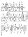
- An electrostatic copying apparatus as an image forming apparatus includes a main body 1 of the copying apparatus or image forming apparatus.
- a photoreceptor drum 2 is disposed within the main body 1 of the copying apparatus.
- the photoreceptor drum 2 is driven by a main motor MM not shown to rotate in the clockwise direction in Figs. 3 and 4.
- Disposed around the photoreceptor drum 2 are an electrostatic charger 3 as electrostatic means, a Selfoc lens 4, a developing device 5 as developing means, a transferring charger 6 as transferring means, a cleaning device 7, and a charge removing lamp 8.
- An exposure lamp 9 as a light source is disposed above the charge removing lamp.
- An original glass plate 10 is supported above the main body 1 of the copying apparatus so as to move in a feed direction which is the moving direction of the original glass plate 10 during a scanning operation (the direction of arrow A) and also in a return direction (the direction of arrow B).
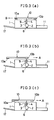
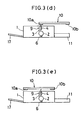
- a first white reflecting plate 10 a as a reflecting unit which reflects the light from the exposure lamp 9 to direct same toward an area between the electrostatic charger 3 and the developing device 5 in the photoreceptor drum 2 through the Selfoc lens 4 when the original glass plate 10 is positioned at an overrun position (Fig. 3 (d)) where its movement in the feed direction is terminated.
- a second white reflecting plate 10b which reflects the light from the exposure lamp 9 to direct same toward the area between the electrostatic charger 3 and the developing device 5 in the photoreceptor drum 2 through the Selfoc lens 4 when the original glass plate 10 is positioned at a start position (Fig. 3 (d)) where its movement in the return direction is terminated.
- a home position sensor HPS for detecting the original glass plate being at its home position
- a start position sensor SPS for detecting the original glass plate 10 being at the start position
- an overrun position sensor OPS for detecting the original glass plate 10 being at the overrun position
- a paper storing member 11 is disposed at one side of a lower portion of the main body 1 of the copying apparatus so that copying sheets 12 housed in the paper storing member 11 are successively supplied, one by one, by means of a feed roller 13 during the process of copying.
- Each sheet 12 fed through the feed roller 13 is supplied to a paper stop roller 16 (hereinafter referred to as PS roller) through an incoming paper detecting switch (PIS) 15 for detecting the supply of the sheet 12 to the photoreceptor drum 2.
- PS roller 16 supplies the sheet 12 to the photoreceptor drum 2 by such timing as is synchronous with the transfer of a toner image from the photoreceptor drum 2.
- a fixing device not shown is disposed at the other side of the lower portion of the main body 1 of the copying apparatus, and a paper discharge tray 17 is disposed in adjoining relation to the fixing device and in the exterior of the main body 1 of the copying apparatus. Further, an outgoing paper detecting switch POS, not shown, for detecting discharge of the copying sheet 12 to the discharge tray 17 is disposed in the main body 1 of the copying apparatus.
- the electrostatic charger 3 is connected to a high voltage transformer 18 as high voltage application means, and the transferring charger 6 is connected through a resistor 19 to the high voltage transformer 18 so that a high voltage trigger is applied from the high voltage transfomer 18 simultaneously to both the electrostatic charger 3 and the transferring charger 6.
- control means not shown, such as a microcomputer or the like.
- the original glass plate 10 supporting an original not shown is first moved from the home position (Fig. 3 (a)) to the start position (Fig. 3 (b)). Thereafter, the original glass plate 10 is moved in the feed direction as the surface of the photoreceptor drum 2 is charged by the electrostatic charger 3 to a predetermined potential, whereby the original is scanned by the exposure lamp 9 (Fig. 3 (c)). Accordingly, a beam of light reflected from the original is projected on to the surface of the photoreceptor drum 2 through the Selfoc lens 4 so that an electrostatic latent image is formed on the surface of the photorecptor drum 2. Subsequently, the electrostatic latent image is developed by toner particles supplied from the developing device 5, a toner image being thus formed on the surface of photoreceptor drum 2.
- the original glass plate 10 Upon completion of the transfer operation, the original glass plate 10 is caused to return to the home position (Fig. 3 (e)), and at the same time the sheet 12 is transported to the fixing device in which image fixation is carried out. Thereafter, the sheet 12 is discharged onto the discharge tray 17. Any residual toner present on the surface of the photoreceptor drum 2 is removed by the cleaning device 7, while any residual charge on the surface of the photoreceptor drum 2 is removed by a beam of light projected from the charge removing lamp 8.
- a standby period follows until the start position sensor SPS is turned on (S7).
- the start position sensor SPS is turned on (Fig. 1 (k))
- the original glass plate return solenoid TRS is turned off, whereupon the movement of the original glass plate 10 is terminated so that the glass plate 10 stops at the start position.
- the high voltage transformer 18 is turned on so that application of a high voltage trigger to the electrostatic charger 3 and transferring charger 6 is commenced (Fig. 1 (h)) and a timer T2 is set (S8).
- a standby period follows until the timer T2 ends its counting operation (S9).
- corona discharge from both the electrostatic charger 3 and the transferring charger 6 is applied to the photoreceptor drum 2.
- the charge applied to the surface of the photoreceptor drum 2 by the electrostatic charger 3 is removed as the light from the exposure lamp 9 is reflected by the white reflecting plate 10b on the original glass plate 10 to illuminate the photoreceptor drum 2 through the Selfoc lens 4.
- the charge applied to the photoreceptor drum 2 by the transferring charger 6 is removed by a beam of light from the charge removing lamp 8.
- cleaning of the photoreceptor drum 2 is carried out. This cleaning operation may be carried out during the period of warming up at step S2.
- the incoming paper detecting switch 15 is ON (Fig. 1 (i))
- decision is made that there is no paper jam whereupon an original glass plate feed solenoid TFS, not shown, is turned on to start power transmission for moving the original glass palte 10 in the feed direction and, simultaneously, a PS roller driving solenoid PSS, not shown, is turned on to transmit power to the PS roller 16 (Figs. 1 (d), 1 (g)) (S11).
- the original glass plate 10 is moved in the feed direction via the home position for an original scanning operation and, at the same time, the sheet 12 is supplied from the PS roller 16 onto the photoreceptor drum 2.
- an electrostatic latent image is formed on the surface of the photoreceptor drum 2 as already mentioned, the electrostatic latent image is sequentially developed by toner particles fed from the developing device 5.
- the original glass plate feed solenoid TFS is turned off so that the original glass plate 10 is stopped at the overrun position, and simultaneously a timer T5 is set (S15).
- This standby time setting by the timer T5 is set to prevent the start of movement of the original glass plate 10 in the return direction when the original glass plate 10 is still moving in the feed direction of feed because of some delay in the turning off action of the original glass plate feed solenoid TFS or under an inertia force of the original glass plate 10.
- the toner image is transferred, by corona discharge from the transferring charger 6, onto copying the sheet 12 fed to the photoreceptor drum 2.
- the photoreceptor drum 2 is naturally subjected to the application of corona charge from the electrostatic charger 3.
- the original glass plate 10 stays at the overrun position and there is continued emission of light from the exposure lamp 9; therefore, the light from the exposure lamp 9 is reflected by the white reflecting plate 10a on the original glass plate 10 to illuminate the photoreceptor drum 2 over its area between the electrostatic charger 3 and the developing device 5 through the Selfoc lens 4, so that the charge which is applied to the non-image area of the photoreceptor drum 2 by the electrostatic charger 3 during the transferring stage is effectively removed.
- step S19 decision is made as to whether or not the home position sensor HPS has been turned on (S19). If it is determined that the original glass plate 10 has returned to the home position, the home position sensor HPS being thus turned on (FIG. 1(m)), a timer T4 is set (S20). Thereafter, when the timer T4 ends counting operation (S21), the original glass plate return solenoid TRS is turned off to terminate the movement of the original glass plate 10 (S22); and a step is taken for copy cycle ending (S23), the program then returning to step S3.
- an embodiment of the image forming apparatus of the invention comprises, in a main body thereof, a light source, a photoreceptor, charging means for electrostatically charging the surface of the photoreceptor, developing means for supplying toner particles to the surface of the photoreceptor, transferring means for transferring onto a copying sheet a toner image formed on the surface of the photoreceptor, and high-voltage applying means for applying a high voltage trigger to both said charging means and said transferring means simultaneously, said apparatus being designed to execute original scanning as an original glass plate is moved with respect to said main body, is characterized in comprising a reflecting unit for reflecting the light from the light source to illuminate the surface of the photoreceptor at an area between the charging means and the developing means, said reflecting unit being disposed at a position corresponding to the trailing end of the original glass plate in its forward movement for original scanning, and control means for causing the original glass plate to stop at an original scanning completing station after the end of the original scanning until the end of the stage of image transferring by the
- the image forming apparatus further comprises a paper detecting switch for detecting the presence or absence of a copying sheet, said switch being disposed in a traveling path of a copying sheet at a location before the station at which the toner image transferring is executed, and a timer for counting a period of time corresponding to the time involved after a copying sheet passes the position of said paper detecting switch until it passes the toner image transfer station said control means being adapted to cause the charge applied to the non-image area of the photoroceptor surface to be removed by the light from the light source until the timing up of said timer.
- Said control means may be of such an arrangement that if, at the end of the stage of toner image transferring onto the copying sheet, a predetermined time has not elapsed after the original glass plate is stopped, the predetermined time is allowed to elapse so that the original glass plate is caused to return to its predetermined position after the original glass plate is definitely stopped.
- the image forming apparatus comprises, in a main body thereof, a light source, a photoreceptor, charging means for electrostatically charging the surface of the photoreceptor, developing means for supplying toner particles to the surface of the photoreceptor, transferring means for transferring onto a copying sheet a toner image formed on the surface of the photoreceptor, and high-voltage applying means for applying a high voltage trigger to both said charging means and said transferring means, said apparatus being designed to execute original scanning as an original glass plate is moved with respect to said main body, is characterized in comprising a reflecting unit for reflecting the light from the light source to illuminate the surface of the photoreceptor at an area between the charging means and the developing means, said reflecting unit being disposed at a position corresponding to the leading end of the original glass plate in its forward movement for original scanning, and control means for causing the original glass plate to stop at an original scanning starting station prior to the start of the original scanning and for causing the light source to emit light so that the charge which is applied to a non
- a reflecting device for reflecting the light from the light source is disposed at the rear end of the original setting glass plate in the moving direction of the original glass plate during an original scanning operation, and it is arranged that the original glass plate stops at the scanning end position after the end of the scanning operation until the end of the image transferring operation by the transferring means and that light emission from the light source is continued until the end of the transferring stage, so that after the end of the scanning operation until the end of the transferring operation, the light reflected from the reflecting device is directed toward the non-image area of the photoreceptor surface between the electrostatic charging means and the developing means, thereby removing, by the reflected light from the reflecting device, the charge applied to the non-image area of the photoreceptor surface by the electrostatic charging means, which continues to carry out corona discharge, in conjunction with the transfer means, even after the end of the scanning operation.
- the reflecting device may be securely fixed on the original glass plate, there being no necessity of providing an independent light source for blank exposure. Therefore, where a common high voltage application means is employed for applying a high voltage trigger to both the electrostatic charging means and the transferring means, the arrangement necessary for blank exposure until the end of the transfer operation can be much more simplified than the prior art arrangement. Further, the arrangement of the invention makes it possible to manufacture the apparatus at a lower cost.
- the arrangement for blank exposure may be simplified, said blank exposure being executed for removing the charge which has been applied to the non-image area of the photoreceptor surface by the cleaning means so that cleaning of the photoreceptor prior to the start of an original scanning operation is performed.
- the completion of transferring a toner image formed on the photoreceptor surface onto a copying sheet is accurately detected thereby to achieve an accurate and precise blank exposure.
Landscapes
- Physics & Mathematics (AREA)
- General Physics & Mathematics (AREA)
- Health & Medical Sciences (AREA)
- Toxicology (AREA)
- Control Or Security For Electrophotography (AREA)
- Electrostatic Charge, Transfer And Separation In Electrography (AREA)
- Exposure Or Original Feeding In Electrophotography (AREA)
Claims (9)
- Bilderzeugungsgerät, bei dem eine auf einen transparenten Träger (10) gelegte Vorlage beleuchtet und abgetastet und ein Abbild der abgetasteten Vorlage fortlaufend auf die elektrostatisch geladene Oberfläche eines lichtempfindlichen Bildträgers (2) projiziert wird, um darauf ein elektrostatisches latentes Bild zu erzeugen, und das latente Bild entwickelt wird, und bei dem das entwickelte Bild auf ein Kopierblatt (12) durch die Funktion einer Transfereinrichtung (6) übertragen wird, die durch eine Hochspannung erregt wird, die gleichzeitig mit dem Anlegen einer Hochspannung an eine Aufladeeinrichtung (3) zugeführt wird, die die elektrostatische Ladung an die Bildträ-geroberfläche anlegt, dadurch gekennzeichnet, daß unmittelbar vor der Abtastung der Vorlagenabbildung Licht von einer Lichtquelle (9), die die Vorlage beleuchtet, veranlaßt wird, von einem an dem Träger (10) angebrachten Reflektorelement (10b) auf die Bildträgeroberfläche zurückzufallen, so daß die Oberfläche fortlaufend gleichmäßig beleuchtet und die Ladung davon entfernt wird.
- Bilderzeugungsgerät nach Anspruch 1, bei dem die Lichtquelle feststehend ist und das Gerät eingerichtet ist, eine Vorlagenabtastung auszuführen, wenn der transparente Träger relativ zu der Lichtquelle bewegt.
- Bilderzeugungsgerät nach Anspruch 2, mit einer Steuereinrichtung, die den transparenten Träger (10) veranlaßt, zwischen aufeinanderfolgenden Vorlagenabtastungen anzuhalten, wobei das Reflektorelement so angeordnet ist, daß Licht die Bildträgeroberfläche beleuchtet.
- Bilderzeugungsgerät nach einem der vorangehenden Ansprüche, bei dem das Reflektorelement (10b) an einer Stelle angeordnet ist, die dem vorderen Ende des transparenten Trägers (10) entspricht, und bei dem Licht von der Lichtquelle (9) die Trägeroberfläche unmittelbar vor der Vorlagenabtastung beleuchtet.
- Bilderzeugungsgerät nach einem der vorangehenden Ansprüche, bei dem ein zweites Reflektorelement (10a) an einer Stelle angeordnet ist, die dem hinteren Ende des transparenten Trägers (10) entspricht, und bei dem Licht von der Lichtquelle (9) die Trägeroberfläche unmittelbar nach der Vorlagenabtastung beleuchtet.
- Bilderzeugungsgerät nach Anspruch 2 oder einem davon abhängenden Anspruch, bei dem die Steuereinrichtung den transparenten Träger (10) veranlaßt, an einer Vorlagenabtastabschlußposition anzuhalten, bis der Bildübertragungsvorgang vollendet ist.
- Bilderzeugungsgerät nach Anspruch 2 oder einem davon abhängenden Anspruch, bei dem die Steuereinrichtung den transparenten Träger (10) veranlaßt, an einer Vorlagenabtastanfangsposition anzuhalten.
- Bilderzeugungsgerät nach einem der vorangehenden Ansprüche, mit einem Papierermittlungsschalter (PIS) zum Ermitteln der Anwesenheit oder Abwesenheit eines Kopierblatts, der in einer Laufbahn eines Kopierblatts angeordnet ist, und einem Zeitnehmer (T3) zum Zählen einer Zeitdauer, die der einbegriffenen Zeit entspricht, nachdem ein Kopierblatt die Position des Papierermittlungsschalters durchläuft, bis es die Bildtransfereinrichtung (6) durchläuft, wobei die Steuereinrichtung eingerichtet ist, zu veranlassen, daß die an einen Nicht-Bildbereich der Photorezeptoroberfläche (2) angelegte Ladung durch das Licht von der Lichtquelle (9) bis zum Ablauf der Zeitdauer entfernt wird.
- Bilderzeugungsgerät nach Anspruch 5 oder einem davon abhängenden Anspruch, bei dem die Steuereinrichtung so eingerichtet ist, daß, wenn bei Vollendung des Tonerbildtransfers eine vorbestimmte Zeit nach dem Anhalten des transparenten Trägers nicht vergangen ist, die vorbestimmte Zeit ablaufen darf, bevor der transparente Träger (10) veranlaßt wird, zu einer vorbestimmten Ruheposition zurückzukehren.
Applications Claiming Priority (2)
| Application Number | Priority Date | Filing Date | Title |
|---|---|---|---|
| JP63135123A JPH01303461A (ja) | 1988-05-31 | 1988-05-31 | 画像形成装置 |
| JP135123/88 | 1988-05-31 |
Publications (3)
| Publication Number | Publication Date |
|---|---|
| EP0345033A2 EP0345033A2 (de) | 1989-12-06 |
| EP0345033A3 EP0345033A3 (en) | 1990-12-12 |
| EP0345033B1 true EP0345033B1 (de) | 1993-11-10 |
Family
ID=15144361
Family Applications (1)
| Application Number | Title | Priority Date | Filing Date |
|---|---|---|---|
| EP89305466A Expired - Lifetime EP0345033B1 (de) | 1988-05-31 | 1989-05-31 | Bildaufzeichnungsgerät |
Country Status (6)
| Country | Link |
|---|---|
| US (1) | US4920379A (de) |
| EP (1) | EP0345033B1 (de) |
| JP (1) | JPH01303461A (de) |
| KR (1) | KR920009698B1 (de) |
| CN (1) | CN1021854C (de) |
| DE (1) | DE68910584T2 (de) |
Families Citing this family (4)
| Publication number | Priority date | Publication date | Assignee | Title |
|---|---|---|---|---|
| JP2595824B2 (ja) * | 1991-02-01 | 1997-04-02 | 富士ゼロックス株式会社 | 画像形成用カートリッジ |
| JP3221045B2 (ja) * | 1992-04-03 | 2001-10-22 | キヤノン株式会社 | 画像形成装置 |
| JP6311307B2 (ja) * | 2013-12-27 | 2018-04-18 | セイコーエプソン株式会社 | 光学モジュール、電子機器、及び光学モジュールの駆動方法 |
| CN105739273B (zh) * | 2014-12-24 | 2019-01-04 | 株式会社理光 | 图像形成装置 |
Family Cites Families (8)
| Publication number | Priority date | Publication date | Assignee | Title |
|---|---|---|---|---|
| JPS5527885Y2 (de) * | 1975-09-09 | 1980-07-03 | ||
| JPS5494038A (en) * | 1978-01-07 | 1979-07-25 | Ricoh Co Ltd | Copier for zerography |
| JPS6049906B2 (ja) * | 1979-05-29 | 1985-11-05 | 松下電器産業株式会社 | 複写機用高圧電源装置 |
| JPS5738442A (en) * | 1980-08-20 | 1982-03-03 | Fuji Xerox Co Ltd | Method for preventing image transfer in copying machine |
| JPS58217962A (ja) * | 1982-06-14 | 1983-12-19 | Canon Inc | 電子写真複写装置 |
| JPS6117166A (ja) * | 1984-07-02 | 1986-01-25 | Konishiroku Photo Ind Co Ltd | 電子複写機 |
| JPS62129869A (ja) * | 1985-11-30 | 1987-06-12 | Mita Ind Co Ltd | 複写機 |
| JPS62174779A (ja) * | 1986-01-28 | 1987-07-31 | Konishiroku Photo Ind Co Ltd | 静電記録装置 |
-
1988
- 1988-05-31 JP JP63135123A patent/JPH01303461A/ja active Pending
-
1989
- 1989-05-29 KR KR1019890007189A patent/KR920009698B1/ko not_active Expired
- 1989-05-31 DE DE68910584T patent/DE68910584T2/de not_active Expired - Lifetime
- 1989-05-31 CN CN89104633A patent/CN1021854C/zh not_active Expired - Lifetime
- 1989-05-31 EP EP89305466A patent/EP0345033B1/de not_active Expired - Lifetime
- 1989-05-31 US US07/359,276 patent/US4920379A/en not_active Expired - Lifetime
Also Published As
| Publication number | Publication date |
|---|---|
| DE68910584T2 (de) | 1994-05-19 |
| DE68910584D1 (de) | 1993-12-16 |
| JPH01303461A (ja) | 1989-12-07 |
| EP0345033A2 (de) | 1989-12-06 |
| KR920009698B1 (ko) | 1992-10-22 |
| CN1039314A (zh) | 1990-01-31 |
| US4920379A (en) | 1990-04-24 |
| KR890017584A (ko) | 1989-12-16 |
| CN1021854C (zh) | 1993-08-18 |
| EP0345033A3 (en) | 1990-12-12 |
Similar Documents
| Publication | Publication Date | Title |
|---|---|---|
| US4662739A (en) | Method of controlling copying machine operation | |
| EP0227328A2 (de) | Kopiergerät | |
| EP0345033B1 (de) | Bildaufzeichnungsgerät | |
| JP2609244B2 (ja) | 複写装置 | |
| US4711552A (en) | Synchronizing electrostatic copy formation | |
| US4548491A (en) | Counterbalance subsystem to accommodate a variable center of gravity | |
| JP2589479B2 (ja) | 画像形成装置における光源制御方法および装置 | |
| US3995950A (en) | Exposure system for electrostatic machines | |
| US4763159A (en) | Multimagnification optical system in a dual mode copier | |
| US4523837A (en) | Document handling system to enable large document copying on a standard office copier | |
| JP2620802B2 (ja) | 画像形成装置 | |
| JP2957369B2 (ja) | 画像形成装置 | |
| JP2605302B2 (ja) | 複写機 | |
| JPH0731249Y2 (ja) | 画像形成装置 | |
| JPH0213303B2 (de) | ||
| JP2004109621A (ja) | 画像形成装置 | |
| JPH0216577A (ja) | 複写装置 | |
| JPS61221736A (ja) | 複写装置 | |
| JPS63204287A (ja) | 画像形成装置 | |
| JPH03269444A (ja) | 複写装置 | |
| JPS6235374A (ja) | 動作タイミング制御装置 | |
| JPS61186949A (ja) | 複写装置 | |
| JPH03118568A (ja) | 自動露光複写機 | |
| JPH0477756A (ja) | 画像形成装置 | |
| JPS61186947A (ja) | 複写装置 |
Legal Events
| Date | Code | Title | Description |
|---|---|---|---|
| PUAI | Public reference made under article 153(3) epc to a published international application that has entered the european phase |
Free format text: ORIGINAL CODE: 0009012 |
|
| 17P | Request for examination filed |
Effective date: 19890623 |
|
| AK | Designated contracting states |
Kind code of ref document: A2 Designated state(s): DE FR GB IT |
|
| PUAL | Search report despatched |
Free format text: ORIGINAL CODE: 0009013 |
|
| AK | Designated contracting states |
Kind code of ref document: A3 Designated state(s): DE FR GB IT |
|
| 17Q | First examination report despatched |
Effective date: 19920717 |
|
| GRAA | (expected) grant |
Free format text: ORIGINAL CODE: 0009210 |
|
| AK | Designated contracting states |
Kind code of ref document: B1 Designated state(s): DE FR GB IT |
|
| REF | Corresponds to: |
Ref document number: 68910584 Country of ref document: DE Date of ref document: 19931216 |
|
| ET | Fr: translation filed | ||
| ITF | It: translation for a ep patent filed | ||
| PLBE | No opposition filed within time limit |
Free format text: ORIGINAL CODE: 0009261 |
|
| STAA | Information on the status of an ep patent application or granted ep patent |
Free format text: STATUS: NO OPPOSITION FILED WITHIN TIME LIMIT |
|
| 26N | No opposition filed | ||
| REG | Reference to a national code |
Ref country code: GB Ref legal event code: IF02 |
|
| PGFP | Annual fee paid to national office [announced via postgrant information from national office to epo] |
Ref country code: DE Payment date: 20080605 Year of fee payment: 20 |
|
| PGFP | Annual fee paid to national office [announced via postgrant information from national office to epo] |
Ref country code: IT Payment date: 20080527 Year of fee payment: 20 |
|
| PGFP | Annual fee paid to national office [announced via postgrant information from national office to epo] |
Ref country code: GB Payment date: 20080604 Year of fee payment: 20 |
|
| REG | Reference to a national code |
Ref country code: GB Ref legal event code: PE20 Expiry date: 20090530 |
|
| PG25 | Lapsed in a contracting state [announced via postgrant information from national office to epo] |
Ref country code: GB Free format text: LAPSE BECAUSE OF EXPIRATION OF PROTECTION Effective date: 20090530 |
|
| PGFP | Annual fee paid to national office [announced via postgrant information from national office to epo] |
Ref country code: FR Payment date: 20080514 Year of fee payment: 20 |