EP0343613B1 - Verfahren für die Kontrolle der exakten Positionierung von Gegenständen zum Sortieren bei einer automatischen Sortieranlage - Google Patents
Verfahren für die Kontrolle der exakten Positionierung von Gegenständen zum Sortieren bei einer automatischen Sortieranlage Download PDFInfo
- Publication number
- EP0343613B1 EP0343613B1 EP89109295A EP89109295A EP0343613B1 EP 0343613 B1 EP0343613 B1 EP 0343613B1 EP 89109295 A EP89109295 A EP 89109295A EP 89109295 A EP89109295 A EP 89109295A EP 0343613 B1 EP0343613 B1 EP 0343613B1
- Authority
- EP
- European Patent Office
- Prior art keywords
- item
- unit
- loading
- speed
- belt
- Prior art date
- Legal status (The legal status is an assumption and is not a legal conclusion. Google has not performed a legal analysis and makes no representation as to the accuracy of the status listed.)
- Expired - Lifetime
Links
- 238000000034 method Methods 0.000 title claims abstract description 49
- 238000011068 loading method Methods 0.000 claims abstract description 46
- 230000006698 induction Effects 0.000 claims description 24
- 230000004888 barrier function Effects 0.000 claims description 6
- 238000001514 detection method Methods 0.000 claims 1
- 230000006870 function Effects 0.000 description 16
- 238000010586 diagram Methods 0.000 description 8
- 230000001133 acceleration Effects 0.000 description 4
- 230000005484 gravity Effects 0.000 description 3
- 230000008569 process Effects 0.000 description 3
- 230000008859 change Effects 0.000 description 2
- 238000012790 confirmation Methods 0.000 description 2
- 230000000694 effects Effects 0.000 description 2
- 238000009434 installation Methods 0.000 description 2
- 230000003993 interaction Effects 0.000 description 2
- FGRBYDKOBBBPOI-UHFFFAOYSA-N 10,10-dioxo-2-[4-(N-phenylanilino)phenyl]thioxanthen-9-one Chemical compound O=C1c2ccccc2S(=O)(=O)c2ccc(cc12)-c1ccc(cc1)N(c1ccccc1)c1ccccc1 FGRBYDKOBBBPOI-UHFFFAOYSA-N 0.000 description 1
- 230000002745 absorbent Effects 0.000 description 1
- 239000002250 absorbent Substances 0.000 description 1
- 238000010276 construction Methods 0.000 description 1
- 230000005347 demagnetization Effects 0.000 description 1
- 238000007599 discharging Methods 0.000 description 1
- 238000004519 manufacturing process Methods 0.000 description 1
- 230000004048 modification Effects 0.000 description 1
- 238000012986 modification Methods 0.000 description 1
- 230000003287 optical effect Effects 0.000 description 1
- 230000001360 synchronised effect Effects 0.000 description 1
- 239000002699 waste material Substances 0.000 description 1
Images


Classifications
-
- B—PERFORMING OPERATIONS; TRANSPORTING
- B65—CONVEYING; PACKING; STORING; HANDLING THIN OR FILAMENTARY MATERIAL
- B65G—TRANSPORT OR STORAGE DEVICES, e.g. CONVEYORS FOR LOADING OR TIPPING, SHOP CONVEYOR SYSTEMS OR PNEUMATIC TUBE CONVEYORS
- B65G43/00—Control devices, e.g. for safety, warning or fault-correcting
- B65G43/08—Control devices operated by article or material being fed, conveyed or discharged
-
- B—PERFORMING OPERATIONS; TRANSPORTING
- B65—CONVEYING; PACKING; STORING; HANDLING THIN OR FILAMENTARY MATERIAL
- B65G—TRANSPORT OR STORAGE DEVICES, e.g. CONVEYORS FOR LOADING OR TIPPING, SHOP CONVEYOR SYSTEMS OR PNEUMATIC TUBE CONVEYORS
- B65G2203/00—Indexing code relating to control or detection of the articles or the load carriers during conveying
- B65G2203/04—Detection means
- B65G2203/042—Sensors
- B65G2203/044—Optical
-
- B—PERFORMING OPERATIONS; TRANSPORTING
- B65—CONVEYING; PACKING; STORING; HANDLING THIN OR FILAMENTARY MATERIAL
- B65G—TRANSPORT OR STORAGE DEVICES, e.g. CONVEYORS FOR LOADING OR TIPPING, SHOP CONVEYOR SYSTEMS OR PNEUMATIC TUBE CONVEYORS
- B65G2207/00—Indexing codes relating to constructional details, configuration and additional features of a handling device, e.g. Conveyors
- B65G2207/18—Crossing conveyors
Definitions
- the present method relates to a method for controlling the exact positioning of the items to be sorted in an automatic sorting plant according to the preamble of claim 1. Such a method is known.
- a plant of this type includes a fixed path along which runs a plurality of carriages or units, on which the items to be sorted are laid; these are unloaded automatically when the relevant carriage passes in correspondence of a collecting area determined when the item is introduced in the apparatus, by means of computer controlled and actuated devices.
- the units are set in motion, according to methods well-known in the art, e.g. by means of a continuous driving chain (solution adopted when the path is substantially a rectilinear one) or by means of electric motors located on board of the units and fed by power bars parallel to the path (solution preferred when the path is a carrousel).
- GB 2 111 933 B relates to a sorting plant comprising a number of carriages movable along a path and provided with a rotating belt, controlled for discharging the items at both sides of the machine into collecting means placed along the path.
- the unloading of the items is carried out by means of mobile belt conveyors forming the load surface of the units. Therefore, when an item is to be unloaded, the belt conveyor of the unit is driven sending tension to the relevant motor by means of bus bars (different from the power ones and sectioned in correspondence of the unloading stations) so as to allow drive control of the only unit-belt conveyor involved in the unloading.
- the unloading may be carried out at both sides of the sorting path simply by inverting the sense of rotation of the belt conveyor, the direction of rotation of which is perpendicular to the unit motion.
- FR 2 182 148 relates to a sorting plant comprising a loading belt angled at 45° with respect to the direction of feed of the items.
- the object of the present invention is to increase precision and reliability of such sorting plants, intervening so as to assure a correct positioning of the item on the conveyance plane. This is achieved with a method according to claim 1.
- the stations are of a well-known type, located at 45° with respect to the direction of motion of the units and formed by three sections where three distinct belt conveyors carry the item towards the chosen unit.
- Said belt conveyors rotate by effect of separate electric motors connected thereto so as to be able to independently vary the speeds of the different sections, the best performances being obtained by use of permanent magnet DC motors.
- the invention consists in the loading process and in particular: - in determining the conveyance speeds of the item along the different sections so as to adjust its position and load the item onto the unit at a null total relative speed; - in the course taken on by said speeds which results to be of continuous kind due to the method by which the changes of speed are carried out.
- the invention is meant to obtain a high precision in positioning the item at the centre of the unit.
- US Pat.4.429.781 HOLZHAUSER discloses an induction station positioned at a certain angle with respect to the direction of movement of the conveyor. Said station presents two distinct sections: on the first one the item is given an acceleration over a determined, constant space, one being able to control said acceleration according to the weight of the item; by the second station the item is loaded onto the conveyor at a constant speed equal to the value reached during the acceleration phase. The loading speed is calculated so as to present a component vectorially equal to the speed of the conveyor and therefore to prevent the item from overturning during the loading phase.
- This method can offer good results when the conveyor is formed by a continuous belt, even if it may cause overturning of items with high center of gravity since the dissipation of the speed component that is to be removed takes place by friction.
- the conveyor instead, consists of carrier units, the above mentioned method is somewhat inaccurate. In fact, it does not take into account the variable position of the item on the induction belt conveyor, which needs a compensation for a precise loading and does not allow to determine the final position of the item on the unit, as said dissipation of speed occurs by friction and does not consider the different masses of the items to be sorted and therefore the different kinetic energies to be removed.
- US Pat. 3.982.625 WENTZ discloses an induction station for sorting machines formed by different mobile belt conveyors by means of which the items are unloaded onto the carrier units presenting a tiltable plate surface.
- An item 1 is placed, either directly by an operator or as it comes from a belt conveyor, onto a synchronization unit 2 made of a mobile belt. While item 1 is in this position, the operator transmits the characterizing data of the item to the central computer 3 by a key-board 4 (e.g. the destination address or the ZIP code).
- a key-board 4 e.g. the destination address or the ZIP code.
- Another means not indicated in the figure to carry out said modification may consist of an optical wand or of an automatic reading system, e.g. of a bar code.
- Computer 3 reserves then one of units 5 which is available and which will be at that moment at a certain distance from induction station 6 and undertakes the necessary functions for conveying the item to the selected unit.
- Synchronization unit 2 has just the function of allowing the operator to carry out coding operations and to place the item onto section A of induction station 6 in periods of time consistent with the computer effected reservation.
- Item 1 thus passes onto section A (position 1a) where it is weighed and conveyed towards section B at a constant speed Vo, having value, e.g., 1 m/s.
- a barrier 7 formed by a series of sensors 8 (e.g. photoelectric cells) apt to detect the size of the item and its position on the belt conveyor of the induction station.
- sensors 8 e.g. photoelectric cells
- These dimensional and topological data are reported to computer 3 and are detected in the following way: - the maximum number of shaded cells and the time during which one cell at least remains shaded (Vo being constant and known) provide the two dimensions of the item; - the position of the shaded cells provides the topological datum.
- Item 1 proceeds at Vo speed as far as the fictitious target X.
- Said target is qualified as fictitious because is established in the memory of computer 3 at a distance from barrier 7 greater than the diagonal of the item having the maximum sizes allowed by the sorting plant.
- the speed of the belt conveyor of section B is brought by computer to the value Vm/ ⁇ 2 (e.g. 1.7 m/s) and the item passes to section C where the belt rotates at the same speed Vm/ ⁇ 2 (where Vm is the motion speed of the units) and proceeds as far as a second target Y (position 1d) the position of which, as it is better illustrated hereinafter, is determined by the computer according to the impulses coming from an encoder 9 connected to the sorting machine.
- the speed of the belt of section C is then increased up to the value Vm ⁇ 2 and the item (position 1e) is then loaded onto the selected unit.
- the object of such method is to obtain the loading of the item perfectly at the centre of the unit reserved by the computer.
- speed Vm/ ⁇ 2 is determining, as well as the moment in which one has to switch from this speed to speed Vm ⁇ 2.
- Item 1 can find target X at any positions on the belt of the induction station and, upon loading (position 1e), the reserved unit has to be in such a position that centre 10 of its loading side correspond to the direction of feed of the item on the induction station.
- the value of speed Vm/ ⁇ 2 compensates for the position of the item on the belt over a period of time which is constant from target X to the beginning of section C and is variable from this point as far as target Y.
- the item may be on the conveyor belt of the induction station in any position, from the right end to the left end of said belt.
- the latter should be in a position consistent with the position of the item at the moment of loading.
- it is necessary to synchronize the position of the unit that has to receive the item with the direction of feed of said item on the induction station, so that the centre of said unit lays, upon loading, along said direction of feed.
- the position of the item on the belt has therefore to be compensated for, by imparting to the item an opportune speed, for a certain period of time.
- Fig.2 shows why said speed has to take on the value Vm/ ⁇ 2.
- the photocells of barrier 7, which detect the position of item 1, can be arranged so that the step between two consecutive photocells be equal to the time elapsing between two impulses of encoder 9, multiplied by the unit speed (encoder step).
- the photocell step may be either a multiple or a fraction of the encoder step: in this case one has recourse to a constant that would either multiply or divide the encoder step with a view to referring it back to the photocell step.
- computer 3 can compare the position of the item on the induction belt with the position of the reserved unit and agree with speed Vm/ ⁇ 2 for a suitable period of time, as long as the target y is reached.
- the target y can be defined as the locus of the points the distance of which from the beginning of Section 3 is equal to the number of impulses of encoder 9 corresponding to the shaded photocells 8.
- item 1 transits on the unit with a direction different from that of the motion of the units and it is required, therefore, that a part of the kinetic energy due to the transit speed be removed.
- the transit of the item on the unit occur at a null total relative speed.
- the loading belt conveyor of the unit is made rotate during transits at a speed vectorially equal to Vm1.
- a further object of the present method is the controlled dissipation of said kinetic energy so as to take into due account mass m of the item to be sorted.
- One of these well-known methods consists of equipping the units with loading surfaces having high coefficient of friction and/or providing them with particular projecting elements. The matter is to turn the spurious kinetic energy into heat by means of the friction generated between the item and the surface of the unit or of the conveyor belt.
- a further method teaches the use, together with surfaces having suitable adherence, of mechanical barriers against which the item knocks and, frequently, rebounds onto the unit. Also in this case we note some inconveniences: the final position of the items, especially if small, is unpredictable; the items having large sizes may set in between the units; the possible use of retainer edges does not solve the problem completely because it may cause mechanical interactions; the fragile parcels may be damaged by the impact.
- the known methods carry out a loading of ballistic type, contrary to the maximum precision required in sorting plants to avoid waste of money due, e.g. to sorting mistakes and to the adoption of large size collecting stations.
- the present method provides a solution of dissipative type , but in a controlled way.
- the unit belt rotates at a speed equal to that of component Vm1. This control is given by the central computer and it allows to prevent the transiting item from overturning.
- Fig. 5 shows the course of the speed module of the item in the period of time, starting from moment t8, in which the item starts its transit on the unit.
- the item keeps speed Vm ⁇ 2 (transit with null total relative speed) over a certain interval t9-t8 so as to be loaded on the unit for the most part; the interval t10-t9 is determined by the drive control controlling the slowing down of the unit belt in function of the mass of the item.
- Fig.6 shows how the dissipative solution can be obtained in a controlled way, by intervening on the feed of the motor setting in rotation the unit belt. It is a matter of comparing the feed tension of said motor with a signal coming from a ramp generator, this signal being controlled by the central computer in function of the mass of the transiting item. It is thus possible to intervene on the feed tension of the motor of the belt-unit so as to obtain a deceleration apt to position the item at the centre of the unit and to control the amount of energy that is to be dissipated.
- Motor 11 of belt 12 of the unit is fed by bars 13 and the tension is controlled by drive control 14.
- Feed-back 15 detects the armature tension of motor 11 and refers it to node 16 which compares it with the signal coming from ramp generator 17. This signal has a form determined by computer 3 in function of the mass of the item in order to obtain a deceleration of the type illustrated in Fig. 5 (t10-t9).
- node 16 acts upon amplifier 18 in order to obtain a tension on bars 13 of variable value, and consistent with the signal of the ramp generator.
- the drive control may be located either on board of the unit or on the ground. From a building point of view the best results are obtained by providing the unit belts with a motor having remarkable acceleration and deceleration characteristics, such as for instance a permanent magnet DC motor.
- the sorting plant according to the present method comprises a unit train that can be handled by different systems,known in the art, such as driving belts, driving units set along the path, motors set onboard of the units themselves. In the latter case two situations may occur: either all the units have a motor on board,or only some of the units are provided with motor,the remaining ones being driven by groups by the said driven units.
- the onboard motor solution becomes therefore preferred and frequent when one wishes to limit the running length of the conveyor or to adapt the installation to pre-existing premises.
- the motors of the units that run along a downhill path absorb a current lower than the nominal one (because they perform a lesser work),and that the amount of non-absorbed current is shared out among the other motors,particularly those that are absorbing their nominal current (e.g. the motors of the uphill running units).
- Said amount can represent an increase in current capable of producing unwanted thermal and electric streses, as well as of causing the demagnetization of the magnets of the DC motors.
- the present method intends,as further object, to assure the proper working current for each motor.
- the driving motor 19 draws the feed by power bars 20 set parallel to the sorting course,through the equalizer 21.
- Said device consists of a variable resistance 22,of an amplifier 23 and a shunt 24,and is calibrated so that the current i that passes through motor 19 does not exceed the nominal value of the motor itself.
- the items are thus carried from the units up to the unloading stations where they are discharged to the respective collecting mouths according to their coding.
- the described method allows a precise loading of the items at the centre of the units, it may occur that, during conveyance, some items shift and arrive at the unloading devices in a position different from the one in which they were upon loading. This mostly occurs when the item has a high center of gravity and when, as it is being conveyed, it falls on its largest bearing surface.
- a furhter object of the present method relates to a re-centering system of those articles which,in the unloading step, are not in the original loading position any longer. It is not always possible to bring the item back to the centre of the unit; however, thanks to the re-centering, the item can be brought to a more suitable position to obtain a predictable and constant discharge trajectory.
- the items having sizes similar to those of the unit may be considered to be,with a fairly good degree of approximation, always at the centre of the unit. In this case the re-centering is important to avoid that the item, in consequence of a fall, jut out of the unit when it comes before the unloading devices.
- the small-size items may arrive at the unloading devices in an off-centered position; in this case the re-centering allows to bring back the item to a position as central as possible.
- the re-centering system consists of two sets 25,26 of photocells 27,28.
- Said photocells adjacent and parallel to the sorting path, are located short before the unloading stations.
- an item 1 When an item 1 has changed its position on the unit, it is intercepted by either of the two sets 25,26 and then brought back to a position as central as possible (position 1′) by means of a revolution of the unit belt.
- the belt is actuated in the arrow direction until there are no more shaded units 28 or until one of the photocells 27 is shaded.
- Photocells 27,28 are divided in two consecutive groups: the first group 26′ and 25′ checks the change in the item position on the unit,whilst the second group 26 ⁇ and 25 ⁇ confirms what the first group has checked.
- a photocell of the first group may happen to be either out of work or dirty,and therefore to signal a situation not corresponding to reality.
- Such a check and check confirmation sequence allows to avoid re-centering errors.
- FIG.10 A different re-centering is shown in Fig.10.
- the solution of Fig.9 does not allow to check the position of items that do not jut out of the units, though being in an off-centered position.
- Fig.10 provides for the convergence of the beams of photocells 28′ and 27′.
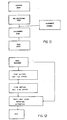
- Figgs. 11-13 show the flow diagrams relevant to the main functions performed by the sorting plant and object of the present method.
- Fig.11 refers to the main functions of the present method, namely the sequence of the loading, re-centering and unloading of the items to be sorted and the test for checking the proper working of the unit belts.
- the "automatic coding" diagram indicates that it is possible to spare the coding operations by installing an automatic code reader (e.g. post code or bar code) before the unloading area. This would allow the reader to automatically scan the item destination and would provide the central computer with the necessary data for the unloading.
- an automatic code reader e.g. post code or bar code
- Fig.12 refers to the functions performed during the loading step.
- the main encoder allows to know the unit position, and the "operator presence" diagram is enabled through the control of the unit speed.
- the item data (adress, post code),codified by the operator, are inserted in the computer and transferred each time to the subsequent devices.
- the item data reach thus the synchronized belt area, where a unit is reserved after referring to the data register of the sorted item.
- section A of the induction station where both position and size are detected, and then to section C (compensation belt), where it is weighed. Then the item proceeds to section 3 (induction belt) to be loaded on to the reserved unit.
- Fig.13 refers to the item re-centering phase before the unloading takes place.
- the unit belt is activated if it needs re-centering,and the operation is over.
Landscapes
- Control Of Conveyors (AREA)
- Sorting Of Articles (AREA)
- Discharge Of Articles From Conveyors (AREA)
- Branching, Merging, And Special Transfer Between Conveyors (AREA)
Claims (12)
Priority Applications (1)
| Application Number | Priority Date | Filing Date | Title |
|---|---|---|---|
| AT89109295T ATE79359T1 (de) | 1988-05-23 | 1989-05-23 | Verfahren fuer die kontrolle der exakten positionierung von gegenstaenden zum sortieren bei einer automatischen sortieranlage. |
Applications Claiming Priority (2)
| Application Number | Priority Date | Filing Date | Title |
|---|---|---|---|
| IT2069588 | 1988-05-23 | ||
| IT20695/88A IT1217694B (it) | 1988-05-23 | 1988-05-23 | Metodo per il controllo dell'esatto posizionamento degli oggetti da smistare in un impianto di smistamento automatico |
Publications (3)
| Publication Number | Publication Date |
|---|---|
| EP0343613A2 EP0343613A2 (de) | 1989-11-29 |
| EP0343613A3 EP0343613A3 (en) | 1990-12-12 |
| EP0343613B1 true EP0343613B1 (de) | 1992-08-12 |
Family
ID=11170685
Family Applications (1)
| Application Number | Title | Priority Date | Filing Date |
|---|---|---|---|
| EP89109295A Expired - Lifetime EP0343613B1 (de) | 1988-05-23 | 1989-05-23 | Verfahren für die Kontrolle der exakten Positionierung von Gegenständen zum Sortieren bei einer automatischen Sortieranlage |
Country Status (8)
| Country | Link |
|---|---|
| US (1) | US4915209A (de) |
| EP (1) | EP0343613B1 (de) |
| AT (1) | ATE79359T1 (de) |
| DE (1) | DE68902422T2 (de) |
| ES (1) | ES2034495T3 (de) |
| GB (2) | GB2218958B (de) |
| IT (1) | IT1217694B (de) |
| RU (1) | RU2004479C1 (de) |
Cited By (8)
| Publication number | Priority date | Publication date | Assignee | Title |
|---|---|---|---|---|
| EP0577021A1 (de) * | 1992-06-30 | 1994-01-05 | Bernhard Beumer Maschinenfabrik KG | Aufgabefördereinrichtung zum Aufgeben von Stückgutteilen auf einen Aufnahmeförderer |
| EP0619248A1 (de) * | 1993-04-01 | 1994-10-12 | Siemens Schweiz AG | Vorrichtung zum Einschleusen von Stückgutteilen auf einen Hauptförderer |
| DE4321958A1 (de) * | 1993-07-01 | 1995-01-19 | Beumer Maschf Bernhard | Verfahren und Vorrichtung zum Verteilen von Stückgut |
| US5588520A (en) * | 1994-09-06 | 1996-12-31 | Rapistan Demag Corp. | Crossbelt sortation system |
| US5803230A (en) * | 1995-07-04 | 1998-09-08 | Sandvik Ab | Device for monitoring the movement of the loading/unloading belt of a transportation carriage, especially for sorting apparatuses |
| US5909796A (en) * | 1995-11-16 | 1999-06-08 | Sandvik Ab | Method and apparatus for loading articles onto vertically spaced platforms of a moving transport device |
| US6129199A (en) * | 1995-09-08 | 2000-10-10 | Siemens Schweiz Ag | Method and device for channeling parceled goods |
| US6455797B1 (en) | 1998-09-28 | 2002-09-24 | Siemens Aktiengesellschaft | Device and method for sorting piece goods |
Families Citing this family (65)
| Publication number | Priority date | Publication date | Assignee | Title |
|---|---|---|---|---|
| NL8901083A (nl) * | 1989-04-28 | 1990-11-16 | Terpa Poultry Bv | Werkwijze en inrichting voor het via een dwarstransporteur afvoeren van verpakte produkten. |
| US5052541A (en) * | 1990-03-19 | 1991-10-01 | Babcock Industries Inc. | Sorter feeder system |
| KR940006086Y1 (ko) * | 1991-12-24 | 1994-09-08 | 주식회사 금성사 | 음극선관용 전자총의 비드써포터 위치 결정장치 |
| US5320209A (en) * | 1992-06-25 | 1994-06-14 | Rockwell International Corporation | Delivery control system for a printing press |
| DK109792D0 (da) * | 1992-09-04 | 1992-09-04 | Cosan Crisplant As | Fremgangsmaade og anlaeg til styret indlaesning af genstande paa en sorteringstransportoer |
| US5335777A (en) * | 1993-10-15 | 1994-08-09 | Jervis B. Webb Company | Method and apparatus for belt conveyor load tracking |
| US5484049A (en) * | 1994-02-22 | 1996-01-16 | United Parcel Service Of America, Inc. | Package measuring system and accumulator |
| CH688711A5 (de) * | 1994-08-02 | 1998-01-30 | Grapha Holding Ag | Vorrichtung zum Beschicken der Behälter eines Verteilförderers. |
| US5860504A (en) * | 1994-11-16 | 1999-01-19 | Lockheed Martin Corporation | Transfer buffer and inserter and method |
| CH689785A5 (de) * | 1995-02-17 | 1999-11-15 | Grapha Holding Ag | Foerderanlage. |
| WO1997014636A1 (en) * | 1995-10-18 | 1997-04-24 | Sandvik Aktiebolag | Sorter mechanism |
| IT1276145B1 (it) | 1995-11-16 | 1997-10-27 | Cml Handling Technology S P A | Apparecchiatura smistatrice con celle di trasporto degli oggetti su piani sovrapposti |
| US5738202A (en) * | 1995-12-21 | 1998-04-14 | Sandvik Sorting Systems, Inc. | Methods and apparatus for establishing a desired positional relationship between random-length articles conveyed in single file |
| IT1285666B1 (it) * | 1996-04-09 | 1998-06-18 | Azionaria Costruzioni Acma Spa | Metodo per l'avanzamento di prodotti |
| DE69827411T2 (de) * | 1997-12-12 | 2005-11-10 | Fki Logistex A/S | Förderanlage und verfahren zu deren betrieb |
| IT1297026B1 (it) * | 1997-12-29 | 1999-08-03 | Cml Handling Technology S P A | Metodo ed apparecchiatura ad elevata produttivita' per lo smistamento dei pacchi |
| IT1301696B1 (it) * | 1998-06-12 | 2000-07-07 | Cml Handling Technology S P A | Metodo ed apparecchiatura per il caricamento automatico di piu'oggetti ordinati, sulla stessa unita' di una macchina smistatrice |
| AU1503400A (en) | 1998-12-01 | 2000-06-19 | Crisplant A/S | A conveyor/sorter system, a loading conveyor and a control system for such conveyors |
| JP2002293425A (ja) * | 1998-12-24 | 2002-10-09 | Techno Wave:Kk | コンベア装置 |
| US6953906B2 (en) | 1999-08-02 | 2005-10-11 | Rapistan Systems Advertising Corp. | Delivery point sequencing mail sorting system with flat mail capability |
| US6323452B1 (en) | 1999-08-05 | 2001-11-27 | United Parcel Service Of America, Inc. | Feeding system and method for placing a plurality of objects on a tray of an automated sorting system |
| US6478138B1 (en) | 1999-10-04 | 2002-11-12 | Rapistan Systems Advertising Corp. | Double width crossbelt sorter |
| US6889814B2 (en) | 2001-05-30 | 2005-05-10 | Rapistan Systems Advertising Corp. | Article sortation system |
| DE10130984B4 (de) * | 2001-06-27 | 2004-03-25 | Knapp Logistik Automation Ges.M.B.H. | Regalbediengerät und Verfahren zum Bedienen eines Produktlagerregals insbesondere einer Kommissioniervorrichtung |
| DE20115478U1 (de) * | 2001-09-19 | 2002-03-21 | Heuft Systemtechnik Gmbh, 56659 Burgbrohl | Vorrichtung zum Ausleiten von Objekten unterschiedlicher Masse |
| US6610955B2 (en) * | 2002-01-31 | 2003-08-26 | Steven W. Lopez | Method and apparatus for multi-task processing and sorting of mixed and non-machinable mailpieces and related methods |
| US7506746B2 (en) * | 2002-08-31 | 2009-03-24 | Applied Materials, Inc. | System for transporting substrate carriers |
| US7234584B2 (en) * | 2002-08-31 | 2007-06-26 | Applied Materials, Inc. | System for transporting substrate carriers |
| US20050095110A1 (en) * | 2002-08-31 | 2005-05-05 | Lowrance Robert B. | Method and apparatus for unloading substrate carriers from substrate carrier transport system |
| US7930061B2 (en) * | 2002-08-31 | 2011-04-19 | Applied Materials, Inc. | Methods and apparatus for loading and unloading substrate carriers on moving conveyors using feedback |
| US7684895B2 (en) * | 2002-08-31 | 2010-03-23 | Applied Materials, Inc. | Wafer loading station that automatically retracts from a moving conveyor in response to an unscheduled event |
| US7243003B2 (en) * | 2002-08-31 | 2007-07-10 | Applied Materials, Inc. | Substrate carrier handler that unloads substrate carriers directly from a moving conveyor |
| DE10346122B4 (de) * | 2003-10-01 | 2013-10-10 | Beumer Gmbh & Co. Kg | Einschleusvorrichtung für einen Sorter |
| US6907978B2 (en) * | 2003-10-09 | 2005-06-21 | Lockheed Martin Corporation | Methods and apparatuses for inducting articles onto a conveyor |
| DE102004004250B4 (de) * | 2004-01-21 | 2007-02-01 | Esterer Wd Gmbh & Co. Kg | Vorrichtung und Verfahren zum Fördern von Holzerzeugnissen |
| US6978192B2 (en) * | 2004-04-02 | 2005-12-20 | Lockheed Martin Corporation | Single pass sequencer and method of use |
| US7591366B2 (en) * | 2005-06-07 | 2009-09-22 | Hytrol Conveyor Company, Inc. | Conveyor system and method for accumulating packages of varying lengths |
| US20070258796A1 (en) * | 2006-04-26 | 2007-11-08 | Englhardt Eric A | Methods and apparatus for transporting substrate carriers |
| US20080035390A1 (en) * | 2006-08-09 | 2008-02-14 | Wurz David A | Dimensioning and weighing system |
| US20080236108A1 (en) * | 2007-03-29 | 2008-10-02 | Parmley Steven M | Package Wrapping Machine with Detection of Lip Features of Trayed Products to be Wrapped |
| DE102007040367B4 (de) * | 2007-08-17 | 2022-11-17 | Ssi Schäfer Automation Gmbh | Materialflusssteuerung zur Kollisionsvermeidung in einer Förderanlage |
| US7938252B2 (en) | 2007-12-21 | 2011-05-10 | Cinetic Sorting Corp. | Unstacking conveyor with floating surface |
| DE102009009519A1 (de) * | 2009-02-18 | 2010-08-26 | Siemens Aktiengesellschaft | Verfahren und Vorrichtung zum Transport eines Gegenstands zu einer Aufnahmeeinrichtung |
| WO2011025942A1 (en) * | 2009-08-28 | 2011-03-03 | Dematic Corp. | Conveyor induct |
| TWI518020B (zh) * | 2010-08-04 | 2016-01-21 | Daifuku Kk | Items sorting equipment |
| US9126234B2 (en) * | 2012-09-17 | 2015-09-08 | Electronics And Telecommunications Research Institute | System for automatically sorting mailpostal matter and method thereof |
| KR20140042993A (ko) | 2012-09-28 | 2014-04-08 | 한국전자통신연구원 | 우편물 구분 시스템 |
| CN104955587B (zh) * | 2012-11-21 | 2018-09-18 | 英特里格拉特德总部有限公司 | 用于分选的动态卸料补偿的方法、材料处理系统以及控制器 |
| FR3011537B1 (fr) * | 2013-10-08 | 2016-01-01 | Cinetic Sorting S P A | Procede et dispositif pour le triage des bagages, capable de traiter des produits peu stables et de formes irregulieres |
| KR102202232B1 (ko) * | 2014-02-05 | 2021-01-13 | 한국전자통신연구원 | 소포 구분 시스템 및 그 방법 |
| CA2945813A1 (en) * | 2014-04-16 | 2015-10-22 | Dematic Corp. | Pre-angling of articles for sortation |
| FR3044648B1 (fr) * | 2015-12-04 | 2018-01-12 | Fives Intralogistics S.A. | Installation de tri d'articles comprenant un systeme de detection et d'analyse de la trajectoire des articles et procede de tri |
| NL2016340B1 (en) | 2016-03-01 | 2017-09-11 | Rexnord Flattop Europe Bv | Method and system for transporting products. |
| NL2017923B1 (en) * | 2016-12-05 | 2018-06-18 | Qimarox Patenten B V | Device and method configured to control rotation of an object on a carrier |
| EP3577030B1 (de) * | 2017-02-01 | 2025-06-25 | Hicof AG | Verfahren und codierungszeile zur serialisierung einer vielzahl von produkten |
| DE102017209984A1 (de) * | 2017-06-13 | 2018-12-13 | Fraunhofer-Gesellschaft zur Förderung der angewandten Forschung e.V. | Verfahren und Vorrichtung zum Umgang mit nicht aufrecht stehenden Artikeln eines Artikelstroms unter Vermeidung von Störungen |
| JP7214314B2 (ja) * | 2017-12-06 | 2023-01-30 | 株式会社京都製作所 | リニア搬送装置 |
| US10569959B1 (en) * | 2018-06-29 | 2020-02-25 | Amazon Technologies, Inc. | Sensor array to transfer an item based on alignment |
| DE102018006014A1 (de) | 2018-07-30 | 2020-01-30 | Interroll Holding Ag | Quergurtsorter mit Steuereinrichtung |
| US11999575B2 (en) | 2019-12-06 | 2024-06-04 | Körber Supply Chain Llc | Parcel processing system and method including hybrid orientation active merge induction equipment |
| US11603270B2 (en) * | 2020-04-28 | 2023-03-14 | Intelligrated Headquarters, Llc | Configuration of a sorter system based on clock cycles |
| DE102021131467A1 (de) | 2021-11-30 | 2023-06-01 | Böwe Systec Gmbh | Vorrichtung zum Sortieren von Poststücken und Verfahren zum Zuführen eines Poststücks zu einer Sortiervorrichtung durch eine Zufuhrvorrichtung |
| CH719300A1 (de) * | 2021-12-22 | 2023-06-30 | Ferag Ag | Verfahren und Vorrichtung zum phasengenauen Übergeben von Stückgut. |
| CN117102050A (zh) * | 2023-08-21 | 2023-11-24 | 德马科技集团股份有限公司 | 物流分拣动作的控制方法、装置、分拣系统及存储介质 |
| JP7751212B2 (ja) * | 2023-10-04 | 2025-10-08 | 株式会社椿本チエイン | 物品搬送装置 |
Family Cites Families (23)
| Publication number | Priority date | Publication date | Assignee | Title |
|---|---|---|---|---|
| US3231068A (en) * | 1963-01-07 | 1966-01-25 | Prospect Mfg Co Inc | Article delivery conveyer |
| US3451522A (en) * | 1966-09-27 | 1969-06-24 | Mo Och Domsjoe Ab | Arrangement for centering and determining the width of workpieces |
| GB1246794A (en) * | 1967-07-21 | 1971-09-22 | G D Peters & Co Ltd | Sorting apparatus |
| US3491903A (en) * | 1967-11-21 | 1970-01-27 | Automatic Sprinkler Corp | Induction scheme and automatic loader |
| US3485339A (en) * | 1967-12-11 | 1969-12-23 | Fairbank Morse Inc | Article spacing system |
| US3550748A (en) * | 1968-07-23 | 1970-12-29 | Itt | Conveyor arrangement |
| US3515254A (en) * | 1968-08-27 | 1970-06-02 | Leo A Gary | Conveyor system having computer for finding the centers of objects being conveyed |
| US4096936A (en) * | 1969-11-03 | 1978-06-27 | Kosan Crisplant A/S | Selectively controllable unloading arrangement for sorting conveyor constructions |
| US3982625A (en) * | 1971-09-03 | 1976-09-28 | American Chain & Cable Company, Inc. | Sorter induction system |
| US3912071A (en) * | 1972-02-29 | 1975-10-14 | Crisplant As | Conveyor system having selective lateral delivery |
| US3747781A (en) * | 1972-04-27 | 1973-07-24 | Rapistan Inc | Induction apparatus |
| US3817368A (en) * | 1972-09-08 | 1974-06-18 | American Chain & Cable Co | Automatic loading system |
| DE2354739A1 (de) * | 1973-11-02 | 1975-05-07 | Renkl Paidiwerk | Vorrichtung zur beschleunigung der foerdergeschwindigkeit von in der fliessfertigung nebeneinanderliegend gefoerderten gegenstaenden |
| DE2547778C3 (de) * | 1975-10-24 | 1986-03-27 | Georg Spiess Gmbh, 8906 Gersthofen | Bogenanleger |
| DE2909292C2 (de) * | 1979-03-09 | 1985-01-03 | Bernhard Beumer Maschinenfabrik Kg, 4720 Beckum | Aufgabevorrichtung zum Aufgeben einzelner Stückgüter auf einen angetriebenen Aufnahmeförderer |
| US4227607A (en) * | 1979-04-16 | 1980-10-14 | Malavenda Peter P | High volume method and system for dynamically storing articles for sorting and routing |
| IT1151648B (it) * | 1982-06-11 | 1986-12-24 | Francesco Canziani | Banco di alimentazione in particolare per macchine di trasporto e smistamento oggetti |
| DK154478C (da) * | 1981-12-24 | 1989-06-12 | Francesco Canziani | Apparat til transport og aflaesning af emner |
| US4815582A (en) * | 1981-12-24 | 1989-03-28 | Francesco Canziani | Feeding apparatus particularly for machines for the conveyance and sorting of objects |
| IT1209579B (it) * | 1984-08-08 | 1989-08-30 | Macario Varese As | Impianto per lo smistamento di colli, con carrelli a movimentazione autonoma. |
| IT211603Z2 (it) * | 1985-12-20 | 1989-04-07 | Canziani Francesco | Unita' di trasporto e scarico per lo smistamento di oggetti. |
| NL8600433A (nl) * | 1986-02-20 | 1987-09-16 | Johannes Gerhardus Christianus | Transportinrichting. |
| IT1197265B (it) * | 1986-09-24 | 1988-11-30 | Francesco Canziani | Metodo per l'azionamento controllato dei dispositivi per lo scarico degli oggetti trasportati, in apparecchiature di smistamento |
-
1988
- 1988-05-23 IT IT20695/88A patent/IT1217694B/it active
- 1988-09-06 US US07/240,920 patent/US4915209A/en not_active Expired - Lifetime
- 1988-09-12 GB GB8821300A patent/GB2218958B/en not_active Expired - Lifetime
-
1989
- 1989-05-22 RU SU894614263A patent/RU2004479C1/ru active
- 1989-05-23 ES ES198989109295T patent/ES2034495T3/es not_active Expired - Lifetime
- 1989-05-23 EP EP89109295A patent/EP0343613B1/de not_active Expired - Lifetime
- 1989-05-23 DE DE8989109295T patent/DE68902422T2/de not_active Expired - Lifetime
- 1989-05-23 AT AT89109295T patent/ATE79359T1/de not_active IP Right Cessation
-
1992
- 1992-01-21 GB GB9201300A patent/GB2251228B/en not_active Expired - Lifetime
Cited By (8)
| Publication number | Priority date | Publication date | Assignee | Title |
|---|---|---|---|---|
| EP0577021A1 (de) * | 1992-06-30 | 1994-01-05 | Bernhard Beumer Maschinenfabrik KG | Aufgabefördereinrichtung zum Aufgeben von Stückgutteilen auf einen Aufnahmeförderer |
| EP0619248A1 (de) * | 1993-04-01 | 1994-10-12 | Siemens Schweiz AG | Vorrichtung zum Einschleusen von Stückgutteilen auf einen Hauptförderer |
| DE4321958A1 (de) * | 1993-07-01 | 1995-01-19 | Beumer Maschf Bernhard | Verfahren und Vorrichtung zum Verteilen von Stückgut |
| US5588520A (en) * | 1994-09-06 | 1996-12-31 | Rapistan Demag Corp. | Crossbelt sortation system |
| US5803230A (en) * | 1995-07-04 | 1998-09-08 | Sandvik Ab | Device for monitoring the movement of the loading/unloading belt of a transportation carriage, especially for sorting apparatuses |
| US6129199A (en) * | 1995-09-08 | 2000-10-10 | Siemens Schweiz Ag | Method and device for channeling parceled goods |
| US5909796A (en) * | 1995-11-16 | 1999-06-08 | Sandvik Ab | Method and apparatus for loading articles onto vertically spaced platforms of a moving transport device |
| US6455797B1 (en) | 1998-09-28 | 2002-09-24 | Siemens Aktiengesellschaft | Device and method for sorting piece goods |
Also Published As
| Publication number | Publication date |
|---|---|
| US4915209A (en) | 1990-04-10 |
| GB2251228A (en) | 1992-07-01 |
| EP0343613A3 (en) | 1990-12-12 |
| EP0343613A2 (de) | 1989-11-29 |
| GB2218958B (en) | 1992-10-14 |
| DE68902422T2 (de) | 1992-12-03 |
| RU2004479C1 (ru) | 1993-12-15 |
| IT1217694B (it) | 1990-03-30 |
| GB2251228B (en) | 1992-10-14 |
| GB8821300D0 (en) | 1988-10-12 |
| GB9201300D0 (en) | 1992-03-11 |
| ES2034495T3 (es) | 1993-04-01 |
| GB2218958A (en) | 1989-11-29 |
| IT8820695A0 (it) | 1988-05-23 |
| ATE79359T1 (de) | 1992-08-15 |
| DE68902422D1 (de) | 1992-09-17 |
Similar Documents
| Publication | Publication Date | Title |
|---|---|---|
| EP0343613B1 (de) | Verfahren für die Kontrolle der exakten Positionierung von Gegenständen zum Sortieren bei einer automatischen Sortieranlage | |
| JP3833734B2 (ja) | 小包搬送方法およびクロスベルト分類装置 | |
| US3880298A (en) | Sorting conveyor control system | |
| EP1042198B1 (de) | Förderanlage und verfahren zu deren betrieb | |
| US6799672B2 (en) | Material sortation system | |
| KR102048330B1 (ko) | 분류 기계에 물품을 공급하기 위한 장치 및 분류 기계 | |
| US6209703B1 (en) | Method and apparatus for the sorting of objects | |
| US5325972A (en) | Method of controlling sorting systems, and a sorting system thus controlled | |
| WO1980001903A1 (en) | Device for supplying parcels and similar articles individually | |
| TWI824073B (zh) | 物品搬送設備 | |
| EP0130810B1 (de) | Förderband-Sortiersystem | |
| GB2144698A (en) | A method for feeding articles to an apparatus with the articles presented according to a predetermined angular disposition, and apparatus for carrying out said method | |
| JPH10509094A (ja) | 搬送物品を仕分けするための装置 | |
| US3866740A (en) | Method of feeding discrete articles from a storage location and a machine therefor | |
| CN115815131A (zh) | 摆轮分拣系统的包裹间距调整方法、系统、控制装置及计算机可读存储介质 | |
| EP0343612B1 (de) | Verfahren und Vorrichtung für die Entladekontrolle von Gegenständen bei einer automatischen Sortiervorrichtung | |
| JPH0551122A (ja) | 荷搬送設備 | |
| JP2509954B2 (ja) | 高速自動仕分装置の荷物移載方法 | |
| JPH0543039A (ja) | 荷搬送設備 | |
| CN118239192A (zh) | 行驶距离计算方法、物流分拣方法、相关装置和介质 | |
| JPH0543037A (ja) | 荷搭載方法 | |
| HK1072764A (en) | A material sortation system | |
| JPS6045090B2 (ja) | 搬送装置への搬送物積込み制御方法 |
Legal Events
| Date | Code | Title | Description |
|---|---|---|---|
| PUAI | Public reference made under article 153(3) epc to a published international application that has entered the european phase |
Free format text: ORIGINAL CODE: 0009012 |
|
| AK | Designated contracting states |
Kind code of ref document: A2 Designated state(s): AT BE CH DE ES FR GR LI LU NL SE |
|
| 17P | Request for examination filed |
Effective date: 19900406 |
|
| PUAL | Search report despatched |
Free format text: ORIGINAL CODE: 0009013 |
|
| AK | Designated contracting states |
Kind code of ref document: A3 Designated state(s): AT BE CH DE ES FR GR LI LU NL SE |
|
| RHK1 | Main classification (correction) |
Ipc: B65G 43/08 |
|
| 17Q | First examination report despatched |
Effective date: 19910418 |
|
| GRAA | (expected) grant |
Free format text: ORIGINAL CODE: 0009210 |
|
| AK | Designated contracting states |
Kind code of ref document: B1 Designated state(s): AT BE CH DE ES FR GR LI LU NL SE |
|
| PG25 | Lapsed in a contracting state [announced via postgrant information from national office to epo] |
Ref country code: GR Free format text: LAPSE BECAUSE OF FAILURE TO SUBMIT A TRANSLATION OF THE DESCRIPTION OR TO PAY THE FEE WITHIN THE PRESCRIBED TIME-LIMIT Effective date: 19920812 Ref country code: AT Effective date: 19920812 |
|
| REF | Corresponds to: |
Ref document number: 79359 Country of ref document: AT Date of ref document: 19920815 Kind code of ref document: T |
|
| REF | Corresponds to: |
Ref document number: 68902422 Country of ref document: DE Date of ref document: 19920917 |
|
| ET | Fr: translation filed | ||
| REG | Reference to a national code |
Ref country code: ES Ref legal event code: FG2A Ref document number: 2034495 Country of ref document: ES Kind code of ref document: T3 |
|
| PG25 | Lapsed in a contracting state [announced via postgrant information from national office to epo] |
Ref country code: LU Free format text: LAPSE BECAUSE OF NON-PAYMENT OF DUE FEES Effective date: 19930531 |
|
| PLBE | No opposition filed within time limit |
Free format text: ORIGINAL CODE: 0009261 |
|
| STAA | Information on the status of an ep patent application or granted ep patent |
Free format text: STATUS: NO OPPOSITION FILED WITHIN TIME LIMIT |
|
| 26N | No opposition filed | ||
| EAL | Se: european patent in force in sweden |
Ref document number: 89109295.9 |
|
| PGFP | Annual fee paid to national office [announced via postgrant information from national office to epo] |
Ref country code: SE Payment date: 19990414 Year of fee payment: 11 |
|
| PGFP | Annual fee paid to national office [announced via postgrant information from national office to epo] |
Ref country code: FR Payment date: 19990511 Year of fee payment: 11 |
|
| PGFP | Annual fee paid to national office [announced via postgrant information from national office to epo] |
Ref country code: ES Payment date: 19990524 Year of fee payment: 11 |
|
| PGFP | Annual fee paid to national office [announced via postgrant information from national office to epo] |
Ref country code: DE Payment date: 19990525 Year of fee payment: 11 |
|
| PGFP | Annual fee paid to national office [announced via postgrant information from national office to epo] |
Ref country code: CH Payment date: 19990526 Year of fee payment: 11 |
|
| PGFP | Annual fee paid to national office [announced via postgrant information from national office to epo] |
Ref country code: NL Payment date: 19990531 Year of fee payment: 11 |
|
| PGFP | Annual fee paid to national office [announced via postgrant information from national office to epo] |
Ref country code: BE Payment date: 19990728 Year of fee payment: 11 |
|
| PG25 | Lapsed in a contracting state [announced via postgrant information from national office to epo] |
Ref country code: SE Free format text: LAPSE BECAUSE OF NON-PAYMENT OF DUE FEES Effective date: 20000524 Ref country code: ES Free format text: THE PATENT HAS BEEN ANNULLED BY A DECISION OF A NATIONAL AUTHORITY Effective date: 20000524 |
|
| PG25 | Lapsed in a contracting state [announced via postgrant information from national office to epo] |
Ref country code: LI Free format text: LAPSE BECAUSE OF NON-PAYMENT OF DUE FEES Effective date: 20000531 Ref country code: CH Free format text: LAPSE BECAUSE OF NON-PAYMENT OF DUE FEES Effective date: 20000531 Ref country code: BE Free format text: LAPSE BECAUSE OF NON-PAYMENT OF DUE FEES Effective date: 20000531 |
|
| BERE | Be: lapsed |
Owner name: CANZIANI FRANCESCO Effective date: 20000531 |
|
| PG25 | Lapsed in a contracting state [announced via postgrant information from national office to epo] |
Ref country code: NL Free format text: LAPSE BECAUSE OF NON-PAYMENT OF DUE FEES Effective date: 20001201 |
|
| REG | Reference to a national code |
Ref country code: CH Ref legal event code: PL |
|
| EUG | Se: european patent has lapsed |
Ref document number: 89109295.9 |
|
| PG25 | Lapsed in a contracting state [announced via postgrant information from national office to epo] |
Ref country code: FR Free format text: LAPSE BECAUSE OF NON-PAYMENT OF DUE FEES Effective date: 20010131 |
|
| NLV4 | Nl: lapsed or anulled due to non-payment of the annual fee |
Effective date: 20001201 |
|
| PG25 | Lapsed in a contracting state [announced via postgrant information from national office to epo] |
Ref country code: DE Free format text: LAPSE BECAUSE OF NON-PAYMENT OF DUE FEES Effective date: 20010301 |
|
| REG | Reference to a national code |
Ref country code: FR Ref legal event code: ST |
|
| REG | Reference to a national code |
Ref country code: ES Ref legal event code: FD2A Effective date: 20020204 |