EP0343464B1 - Schienenfahrzeug mit Einzelrädern - Google Patents
Schienenfahrzeug mit Einzelrädern Download PDFInfo
- Publication number
- EP0343464B1 EP0343464B1 EP89108660A EP89108660A EP0343464B1 EP 0343464 B1 EP0343464 B1 EP 0343464B1 EP 89108660 A EP89108660 A EP 89108660A EP 89108660 A EP89108660 A EP 89108660A EP 0343464 B1 EP0343464 B1 EP 0343464B1
- Authority
- EP
- European Patent Office
- Prior art keywords
- bearings
- rail vehicle
- temperature
- infra
- temperature sensor
- Prior art date
- Legal status (The legal status is an assumption and is not a legal conclusion. Google has not performed a legal analysis and makes no representation as to the accuracy of the status listed.)
- Expired - Lifetime
Links
- 238000010438 heat treatment Methods 0.000 claims abstract description 5
- 239000004020 conductor Substances 0.000 abstract 1
- 230000005855 radiation Effects 0.000 description 4
- 230000001154 acute effect Effects 0.000 description 2
- 238000010586 diagram Methods 0.000 description 2
- 238000012544 monitoring process Methods 0.000 description 2
- 230000003137 locomotive effect Effects 0.000 description 1
Images

Classifications
-
- B—PERFORMING OPERATIONS; TRANSPORTING
- B61—RAILWAYS
- B61K—AUXILIARY EQUIPMENT SPECIALLY ADAPTED FOR RAILWAYS, NOT OTHERWISE PROVIDED FOR
- B61K9/00—Railway vehicle profile gauges; Detecting or indicating overheating of components; Apparatus on locomotives or cars to indicate bad track sections; General design of track recording vehicles
- B61K9/04—Detectors for indicating the overheating of axle bearings and the like, e.g. associated with the brake system for applying the brakes in case of a fault
Definitions
- the invention relates to a rail vehicle with individual wheels which are held independently of one another in each case in bearings arranged outside and inside next to the wheel disc, with an inadmissibly high heating of the outer bearing being able to be monitored by stationary infrared devices.
- the invention has for its object to enable the temperature monitoring of the inner bearings with the same stationary systems in a simple manner.
- thermosensor is assigned to the inner bearing, which, when the inner bearing is heated appropriately, ensures that an infrared transmitter mounted externally in the height plane of the outer bearing is electrically heated.
- the stationary systems are also set up in such a way that the axis number of the passing train, in which there is a hot warehouse, is located and reported.
- the infrared transmitter is arranged in the vicinity of the outer bearing.
- a rod-shaped temperature sensor 5 (thermistor) is screwed into the housing 3a of each inner bearing 3 and closes a circuit 9 when an excessive bearing temperature is reached.
- the heat radiation emitted by the infrared transmitter 6 is emitted by stationary infrared devices 4 next to the rails 10 received and sent as information to employees, for example in the next train station. Since the infrared transmitter 6 is located near the outer bearing 2, the staff are also informed about which axis of the incoming train contains the hot runner.
- a relay 7 is arranged between the temperature sensor 5 and the infrared transmitter 6.
- the source for the control current is 11, that for the heating current is 12.
- an acute hot runner is assigned a storage temperature of approximately 120 ° C; the preliminary stage for an acute hot runner - a so-called warm runner - should be available from an assumed 70 ° C.
- the outer bearings 2 the location of both warm and hot runners is easily possible due to the proportional heat radiation.
- the inner bearings 3 the aforementioned location is e.g. Two-stage design of the temperature sensor 5 with corresponding heating of the infrared sensor 6 (70 ° C or 120 ° C) possible.
- two temperature sensors 5 and two infrared sensors 6 can be used, which are set to 70 ° C and 120 ° C.
Landscapes
- Engineering & Computer Science (AREA)
- Mechanical Engineering (AREA)
- Rolling Contact Bearings (AREA)
- Electric Propulsion And Braking For Vehicles (AREA)
- Vehicle Body Suspensions (AREA)
- Escalators And Moving Walkways (AREA)
- Motorcycle And Bicycle Frame (AREA)
Description
- Die Erfindung betrifft ein Schienenfahrzeug mit Einzelrädern, die unabhängig voneinander jeweils in außen und innen neben der Radscheibe angeordneten Lagerungen gehalten sind, wobei eine unzulässig hohe Erwärmung der äußeren Lagerung durch stationäre Infrarotgeräte überwachbar ist.
- Zum Stand der Technik wird auf den in der Zeitschrift "Eisenbahntechnische Rundschau" (ETR) 1977, Seiten 81 bis 88 erschienenen Aufsatz mit dem Titel "Temperaturüberwachung der Radsatzrollenlager an Wagen der Deutschen Bundesbahn" hingewiesen. Wie diesem Aufsatz zu entnehmen ist, lassen sich trotz sorgfältiger Behandlung der Lager gelegentlich auftretende Heißläufer nicht vermeiden. Das Orten dieser Heißläufer kann durch stationäre Anlagen erfolgen, die im wesentlichen aus Infrarotgeräten bestehen. Diese außerhalb der Schienen liegenden Geräte sind unter einem engen Meßwinkel auf die äußeren Lager von Radsätzen ausgerichtet, so daß allein die Wärmeabstrahlung dieser Lager und möglichst keine anderen heißen Teile des Zuges (beispielsweise die Aggregate von Lokomotiven) erfaßt werden.
- Bei drehgestellähnlichen Fahrwerken sind jeweils doppelt gelagerte Einzelräder bekannt (EP-A-0050727). Mit Hilfe der vorgenannten stationären Anlagen (Infrarotgeräte) ist zwar die Temperatur der äußeren Lagerungen überwachbar, jedoch sind diese Anlagen nicht auf die inneren Lagerungen ausgerichtet.
- Der Erfindung liegt die Aufgabe zugrunde, auf einfache Weise die Temperaturüberwachung der inneren Lagerungen mit denselben stationären Anlagen zu ermöglichen.
- Diese Aufgabe wird erfindungsgemäß dadurch gelöst, daß der inneren Lagerung ein Temperaturfühler (Heißleiter) zugeordnet ist, der ab einer entsprechenden Erwärmung der inneren Lagerung dafür sorgt, daß ein außen in der Höhenebene der äußeren Lagerung angebrachter Infrarotgeber elektrisch aufgeheizt wird.
- Bei dem Gegenstand nach der Erfindung wird im Falle einer Erhitzung der inneren Lagerungen eine entsprechende infrarote Wärmestrahlung im Bereich der äußeren Lagerungen erzeugt, die vorteilhaft von vorhandenen stationären Anlagen erfaßbar ist.
- Die stationären Anlagen sind auch derart eingerichtet, daß die Achsnummer des vorbeifahrenden Zuges, in der sich ein heißes Lager befindet, lokalisiert und gemeldet wird. Im Hinblick darauf ist nach einer Ausgestaltung der Erfindung vorgesehen, daß der Infrarotgeber in der Nähe der äußeren Lagerung angeordnet ist.
- Weitere Ausgestaltungen der Erfindung sind in den übrigen Unteransprüchen angegeben.
- Ein Ausführungsbeispiel der Erfindung ist in der Zeichnung schematisch dargestellt und wird im folgenden näher beschrieben. Es zeigen
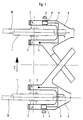
- Fig. 1
- einen Teilbereich eines Fahrwerkes für Schienenfahrzeuge, in Draufsicht,
- Fig. 2
- die Ansicht in Richtung des Pfeiles Z in Fig. 1,
- Fig. 3
- ein prinzipielles Schaltbild.
- An gabelförmig ausgebildeten Enden des Fahrwerkrahmens 8 sind unabhängig voneinander drehbare Einzelräder in jeweils außen und innen neben der Radscheibe 1 angeordneten Lagerungen 2 bzw. 3 gehalten. Wie in Fig. 2 anhand der inneren Lagerung 3 gezeigt, sind die Gehäuse der Lagerungen 2 und 3 zweiteilig gestaltet, um jedes Einzelrad leicht ein- und ausbauen zu können.
- In das Gehäuse 3a jeder inneren Lagerung 3 ist ein stabförmig ausgebildeter Temperaturfühler 5 (Heißleiter) eingeschraubt, der bei Erreichen einer überhöhten Lagertemperatur einen Stromkreis 9 schließt. Ein mit diesem Stromkreis 9 verbundener Infrarotgeber 6, der in der Nähe und in Höhenebene der äußeren Lagerung 2 am Fahrwerkrahmen 8 angebracht ist, wird dann elektrisch aufgeheizt. Die vom Infrarotgeber 6 ausgehende Wärmestrahlung wird von stationären Infrarotgeräten 4 neben den Schienen 10 empfangen und als Information an Bedienstete beispielsweise im nächsten Bahnhof gesendet. Da der Infrarotgeber 6 in der Nähe der äußeren Lagerung 2 liegt, sind die Bediensteten auch darüber informiert, welche Achse des ankommenden Zuges den Heißläufer beinhaltet.
- Gemäß dem in Fig. 3 wiedergegebenen prinzipiellen Schaltbild ist zwischen dem Temperaturfühler 5 und dem Infrarotgeber 6 ein Relais 7 angeordnet. Die Quelle für den Steuerstrom ist mit 11, die für den Heizstrom mit 12 bezeichnet.
- Für die weitere Erläuterung des Ausführungsbeispiels wird einem akuten Heißläufer eine Lagertemperatur von ca. 120°C zugeordnet; die Vorstufe zu einem akuten Heißläufer ― ein sogenannter Warmläufer ― soll ab angenommen 70°C vorliegen. Bezüglich der äußeren Lagerungen 2 ist das Orten sowohl von Warmläufern als auch von Heißläufern wegen der jeweils proportionalen Wärmeabstrahlung ohne weiteres möglich. Bezogen auf die inneren Lagerungen 3 ist das vorgenannte Orten durch z.B. zweistufige Auslegung des Temperaturfühlers 5 mit entsprechender Aufheizung des Infrarotgebers 6 (70°C bzw. 120°C) möglich. Alternativ kann mit zwei Temperaturfühlern 5 und zwei Infrarotgebern 6 gearbeitet werden, die zum einen auf 70°C, zum anderen auf 120°C eingestellt sind.
Claims (5)
Priority Applications (1)
| Application Number | Priority Date | Filing Date | Title |
|---|---|---|---|
| AT89108660T ATE66879T1 (de) | 1988-05-21 | 1989-05-13 | Schienenfahrzeug mit einzelraedern. |
Applications Claiming Priority (2)
| Application Number | Priority Date | Filing Date | Title |
|---|---|---|---|
| DE3817431A DE3817431A1 (de) | 1988-05-21 | 1988-05-21 | Schienenfahrzeug mit einzelraedern |
| DE3817431 | 1988-05-21 |
Publications (2)
| Publication Number | Publication Date |
|---|---|
| EP0343464A1 EP0343464A1 (de) | 1989-11-29 |
| EP0343464B1 true EP0343464B1 (de) | 1991-09-04 |
Family
ID=6354909
Family Applications (1)
| Application Number | Title | Priority Date | Filing Date |
|---|---|---|---|
| EP89108660A Expired - Lifetime EP0343464B1 (de) | 1988-05-21 | 1989-05-13 | Schienenfahrzeug mit Einzelrädern |
Country Status (4)
| Country | Link |
|---|---|
| EP (1) | EP0343464B1 (de) |
| AT (1) | ATE66879T1 (de) |
| DE (2) | DE3817431A1 (de) |
| ES (1) | ES2024062B3 (de) |
Families Citing this family (2)
| Publication number | Priority date | Publication date | Assignee | Title |
|---|---|---|---|---|
| DE4107649A1 (de) * | 1991-03-09 | 1992-09-10 | Duewag Ag | Einrichtung zum ueberwachen der lagertemperatur von schienenfahrzeugraedern |
| ES2130039B1 (es) * | 1996-04-17 | 2000-02-16 | Talgo Patentes | Conjunto de eje ferroviario dotado de cambio automatico de ancho de via y adaptable a bogies convencionales de mercancias. |
Family Cites Families (4)
| Publication number | Priority date | Publication date | Assignee | Title |
|---|---|---|---|---|
| US3183349A (en) * | 1959-10-30 | 1965-05-11 | Barnes Eng Co | Hot box detector |
| BE790389A (fr) * | 1971-10-21 | 1973-02-15 | Jaeger Gmbh G & J | Installation de surveillance de paliers de train de roues |
| DE3039369A1 (de) * | 1980-10-18 | 1982-06-03 | Duewag AG, 4150 Krefeld | Drehgestell fuer schienenfahrzeuge |
| EP0263217B1 (de) * | 1986-09-09 | 1991-07-31 | CSEE-Transport | System zum Erkennen unzulässig erwärmter Bauteile an fahrenden Schienenfahrzeugen |
-
1988
- 1988-05-21 DE DE3817431A patent/DE3817431A1/de active Granted
-
1989
- 1989-05-13 AT AT89108660T patent/ATE66879T1/de active
- 1989-05-13 DE DE8989108660T patent/DE58900256D1/de not_active Expired - Fee Related
- 1989-05-13 ES ES89108660T patent/ES2024062B3/es not_active Expired - Lifetime
- 1989-05-13 EP EP89108660A patent/EP0343464B1/de not_active Expired - Lifetime
Also Published As
| Publication number | Publication date |
|---|---|
| DE3817431C2 (de) | 1991-02-07 |
| ES2024062B3 (es) | 1992-02-16 |
| ATE66879T1 (de) | 1991-09-15 |
| DE58900256D1 (de) | 1991-10-10 |
| EP0343464A1 (de) | 1989-11-29 |
| DE3817431A1 (de) | 1989-11-23 |
Similar Documents
| Publication | Publication Date | Title |
|---|---|---|
| EP0571852B1 (de) | Radsatzdiagnoseeinrichtung zur Überwachung fahrender Eisenbahnfahrzeuge | |
| EP0041178B1 (de) | Vorrichtung zum Erkennen unzulässig erwärmter Bauteile an fahrenden Eisenbahnwagen | |
| DE2343904A1 (de) | Verfahren zur messung der temperatur von achslagern bei schienenfahrzeugen | |
| EP0343464B1 (de) | Schienenfahrzeug mit Einzelrädern | |
| DE4242659A1 (de) | Vorrichtung zum Transport mindestens einer Kanne zwischen einer faserbandabliefernden Spinnereimaschine, z. B. Karde und einer fasergespeisten Spinnereimaschine, z. B. Strecke | |
| DE102011051330A1 (de) | Vorsatzrahmen für Kommissionierwagen | |
| EP0263217B1 (de) | System zum Erkennen unzulässig erwärmter Bauteile an fahrenden Schienenfahrzeugen | |
| DE4107649C2 (de) | ||
| DE2130328C2 (de) | Fahrbare Einrichtung zur Feststellung der Höhenlage bzw. des Zustandes eines Gleises | |
| EP0188287A3 (de) | Oberleitungs-Stromabnehmer für spurungebundene Fahrzeuge | |
| DE29620865U1 (de) | Halterung von Batteriecontainern an Bahnfahrzeugen | |
| DE3405154C2 (de) | ||
| DE3417353C2 (de) | Umlaufförderer | |
| DE4206755C2 (de) | Anlage mit einem schienengebundenen Hüttenfahrzeug | |
| DE2703508C2 (de) | ||
| EP0548637A1 (de) | Anordnung zur Überwachung der Achslagertemperatur | |
| AT250432B (de) | Einrichtung zur Standortmeldung von Fahrbetriebsmitteln von Seilbahnen | |
| DE14550C (de) | Neuerungen an elektromagnetischen Signalvorrichtungen für Eisenbahnen | |
| EP1433650B1 (de) | Vorrichtung zum Erden eines Eisenbahnfahrzeugs | |
| DE1755721C3 (de) | Vorrichtung an zur Messung und/oder Korrektur der Lage von Gleisen dienenden Fahrzeugen | |
| DE2544260A1 (de) | Bahnanlage, bei der die spurfuehrung der fahrzeuge auf der strecke abhaengig von einem in der mitte der spur sich erstreckenden leitmittel erfolgt | |
| DE1219403B (de) | Fahrbarer, beheizbarer Wagen fuer Gefriertrocknungskammern | |
| DE385247C (de) | Gelenkdrehscheibe | |
| DE660083C (de) | Fahrbare elektrische Schaltanlage | |
| EP0831004A2 (de) | Schienengeleitetes Fahrzeug |
Legal Events
| Date | Code | Title | Description |
|---|---|---|---|
| PUAI | Public reference made under article 153(3) epc to a published international application that has entered the european phase |
Free format text: ORIGINAL CODE: 0009012 |
|
| AK | Designated contracting states |
Kind code of ref document: A1 Designated state(s): AT BE CH DE ES FR GB GR IT LI LU NL SE |
|
| 17P | Request for examination filed |
Effective date: 19891213 |
|
| RIN1 | Information on inventor provided before grant (corrected) |
Inventor name: HOHNSTAEDT, KLAUS Inventor name: VON MADEYSKI, THILO, DR.-ING. Inventor name: BRAUN, OTTO Inventor name: SCHRAUT, ROLF, DR.-ING. |
|
| 17Q | First examination report despatched |
Effective date: 19901022 |
|
| GRAA | (expected) grant |
Free format text: ORIGINAL CODE: 0009210 |
|
| AK | Designated contracting states |
Kind code of ref document: B1 Designated state(s): AT BE CH DE ES FR GB GR IT LI LU NL SE |
|
| PG25 | Lapsed in a contracting state [announced via postgrant information from national office to epo] |
Ref country code: GR Free format text: LAPSE BECAUSE OF FAILURE TO SUBMIT A TRANSLATION OF THE DESCRIPTION OR TO PAY THE FEE WITHIN THE PRESCRIBED TIME-LIMIT Effective date: 19910904 |
|
| REF | Corresponds to: |
Ref document number: 66879 Country of ref document: AT Date of ref document: 19910915 Kind code of ref document: T |
|
| REF | Corresponds to: |
Ref document number: 58900256 Country of ref document: DE Date of ref document: 19911010 |
|
| GBT | Gb: translation of ep patent filed (gb section 77(6)(a)/1977) | ||
| ITF | It: translation for a ep patent filed | ||
| ET | Fr: translation filed | ||
| REG | Reference to a national code |
Ref country code: ES Ref legal event code: FG2A Ref document number: 2024062 Country of ref document: ES Kind code of ref document: B3 |
|
| PLBE | No opposition filed within time limit |
Free format text: ORIGINAL CODE: 0009261 |
|
| STAA | Information on the status of an ep patent application or granted ep patent |
Free format text: STATUS: NO OPPOSITION FILED WITHIN TIME LIMIT |
|
| 26N | No opposition filed | ||
| EPTA | Lu: last paid annual fee | ||
| EAL | Se: european patent in force in sweden |
Ref document number: 89108660.5 |
|
| PGFP | Annual fee paid to national office [announced via postgrant information from national office to epo] |
Ref country code: SE Payment date: 19970416 Year of fee payment: 9 |
|
| PGFP | Annual fee paid to national office [announced via postgrant information from national office to epo] |
Ref country code: GB Payment date: 19970417 Year of fee payment: 9 |
|
| PGFP | Annual fee paid to national office [announced via postgrant information from national office to epo] |
Ref country code: NL Payment date: 19970428 Year of fee payment: 9 |
|
| PGFP | Annual fee paid to national office [announced via postgrant information from national office to epo] |
Ref country code: ES Payment date: 19970513 Year of fee payment: 9 |
|
| PGFP | Annual fee paid to national office [announced via postgrant information from national office to epo] |
Ref country code: LU Payment date: 19970702 Year of fee payment: 9 |
|
| PGFP | Annual fee paid to national office [announced via postgrant information from national office to epo] |
Ref country code: FR Payment date: 19980408 Year of fee payment: 10 |
|
| PGFP | Annual fee paid to national office [announced via postgrant information from national office to epo] |
Ref country code: AT Payment date: 19980415 Year of fee payment: 10 |
|
| PGFP | Annual fee paid to national office [announced via postgrant information from national office to epo] |
Ref country code: CH Payment date: 19980428 Year of fee payment: 10 |
|
| PGFP | Annual fee paid to national office [announced via postgrant information from national office to epo] |
Ref country code: BE Payment date: 19980512 Year of fee payment: 10 |
|
| PG25 | Lapsed in a contracting state [announced via postgrant information from national office to epo] |
Ref country code: LU Free format text: LAPSE BECAUSE OF NON-PAYMENT OF DUE FEES Effective date: 19980513 Ref country code: GB Free format text: LAPSE BECAUSE OF NON-PAYMENT OF DUE FEES Effective date: 19980513 |
|
| PG25 | Lapsed in a contracting state [announced via postgrant information from national office to epo] |
Ref country code: SE Free format text: LAPSE BECAUSE OF NON-PAYMENT OF DUE FEES Effective date: 19980514 Ref country code: ES Free format text: LAPSE BECAUSE OF NON-PAYMENT OF DUE FEES Effective date: 19980514 |
|
| PGFP | Annual fee paid to national office [announced via postgrant information from national office to epo] |
Ref country code: DE Payment date: 19980616 Year of fee payment: 10 |
|
| PG25 | Lapsed in a contracting state [announced via postgrant information from national office to epo] |
Ref country code: NL Free format text: LAPSE BECAUSE OF NON-PAYMENT OF DUE FEES Effective date: 19981201 |
|
| GBPC | Gb: european patent ceased through non-payment of renewal fee |
Effective date: 19980513 |
|
| EUG | Se: european patent has lapsed |
Ref document number: 89108660.5 |
|
| NLV4 | Nl: lapsed or anulled due to non-payment of the annual fee |
Effective date: 19981201 |
|
| PG25 | Lapsed in a contracting state [announced via postgrant information from national office to epo] |
Ref country code: AT Free format text: LAPSE BECAUSE OF NON-PAYMENT OF DUE FEES Effective date: 19990513 |
|
| PG25 | Lapsed in a contracting state [announced via postgrant information from national office to epo] |
Ref country code: LI Free format text: LAPSE BECAUSE OF NON-PAYMENT OF DUE FEES Effective date: 19990531 Ref country code: CH Free format text: LAPSE BECAUSE OF NON-PAYMENT OF DUE FEES Effective date: 19990531 Ref country code: BE Free format text: LAPSE BECAUSE OF NON-PAYMENT OF DUE FEES Effective date: 19990531 |
|
| BERE | Be: lapsed |
Owner name: DUEWAG A.G. Effective date: 19990531 |
|
| REG | Reference to a national code |
Ref country code: CH Ref legal event code: PL |
|
| PG25 | Lapsed in a contracting state [announced via postgrant information from national office to epo] |
Ref country code: FR Free format text: LAPSE BECAUSE OF NON-PAYMENT OF DUE FEES Effective date: 20000131 |
|
| PG25 | Lapsed in a contracting state [announced via postgrant information from national office to epo] |
Ref country code: DE Free format text: LAPSE BECAUSE OF NON-PAYMENT OF DUE FEES Effective date: 20000301 |
|
| REG | Reference to a national code |
Ref country code: FR Ref legal event code: ST |
|
| REG | Reference to a national code |
Ref country code: ES Ref legal event code: FD2A Effective date: 20000403 |
|
| PG25 | Lapsed in a contracting state [announced via postgrant information from national office to epo] |
Ref country code: IT Free format text: LAPSE BECAUSE OF NON-PAYMENT OF DUE FEES Effective date: 20050513 |