EP0343450A1 - Stuhl, insbesondere Arbeits- oder Bürostuhl - Google Patents
Stuhl, insbesondere Arbeits- oder Bürostuhl Download PDFInfo
- Publication number
- EP0343450A1 EP0343450A1 EP89108563A EP89108563A EP0343450A1 EP 0343450 A1 EP0343450 A1 EP 0343450A1 EP 89108563 A EP89108563 A EP 89108563A EP 89108563 A EP89108563 A EP 89108563A EP 0343450 A1 EP0343450 A1 EP 0343450A1
- Authority
- EP
- European Patent Office
- Prior art keywords
- seat
- backrest
- chair
- inclination
- chair according
- Prior art date
- Legal status (The legal status is an assumption and is not a legal conclusion. Google has not performed a legal analysis and makes no representation as to the accuracy of the status listed.)
- Granted
Links
- 230000004075 alteration Effects 0.000 abstract 1
- 238000006073 displacement reaction Methods 0.000 description 3
- 230000007704 transition Effects 0.000 description 3
- 230000006978 adaptation Effects 0.000 description 1
- 230000005540 biological transmission Effects 0.000 description 1
- 230000003287 optical effect Effects 0.000 description 1
- 230000001360 synchronised effect Effects 0.000 description 1
Images

Classifications
-
- A—HUMAN NECESSITIES
- A47—FURNITURE; DOMESTIC ARTICLES OR APPLIANCES; COFFEE MILLS; SPICE MILLS; SUCTION CLEANERS IN GENERAL
- A47C—CHAIRS; SOFAS; BEDS
- A47C3/00—Chairs characterised by structural features; Chairs or stools with rotatable or vertically-adjustable seats
- A47C3/02—Rocking chairs
- A47C3/025—Rocking chairs with seat, or seat and back-rest unit elastically or pivotally mounted in a rigid base frame
- A47C3/026—Rocking chairs with seat, or seat and back-rest unit elastically or pivotally mounted in a rigid base frame with central column, e.g. rocking office chairs; Tilting chairs
-
- A—HUMAN NECESSITIES
- A47—FURNITURE; DOMESTIC ARTICLES OR APPLIANCES; COFFEE MILLS; SPICE MILLS; SUCTION CLEANERS IN GENERAL
- A47C—CHAIRS; SOFAS; BEDS
- A47C1/00—Chairs adapted for special purposes
- A47C1/02—Reclining or easy chairs
- A47C1/031—Reclining or easy chairs having coupled concurrently adjustable supporting parts
- A47C1/032—Reclining or easy chairs having coupled concurrently adjustable supporting parts the parts being movably-coupled seat and back-rest
- A47C1/03255—Reclining or easy chairs having coupled concurrently adjustable supporting parts the parts being movably-coupled seat and back-rest with a central column, e.g. rocking office chairs
Definitions
- the invention relates to a chair, in particular a work or office chair, with a seat which can be pivoted in the front region about a horizontal pivot axis and whose inclination can be changed and, depending on the change in inclination of the seat, by means of an adjusting device, the inclination of the backrest which can be changed disproportionately, in which with increasing inclination of the seat, the backrest executes an additional relative movement downward relative to the facing end of the seat.
- the known chairs of this type offer excellent seating comfort, since on the one hand they provide a clear support for the back of the user in the starting or working position thanks to the practically vertical position of the backrest, but on the other hand they allow relaxed sitting after the backrest is tilted backwards.
- the backrest When the backrest is tilted backwards, the user's upper body does not simply make a swiveling movement, but rather a movement superimposed from various movement components results. Since the backrest performs an additional downward movement towards the seat when tilting backwards, a relative movement between the back of the user and the backrest is avoided or at least reduced to an undetectable value.
- the chair can be designed as a synchronous chair, in which a downward inclination of the seat support carrying the seat inevitably brings about a backward inclination of the backrest bar with a larger angle of inclination.
- the seat support with the seat can also be guided to be extendable on the bearing block.
- multi-link lever chains are used, as shown in EP 0 176 816 A1, or, on the other hand, pairs of transmission levers and drive arches as shown in EP 0 085 870 A1.
- many parts are required for the adjustment device.
- the same also applies to a chair according to DE 29 16 897 A1, in which, when the seat is pulled out, the backrest on the backrest bar is displaced in the direction of the seat.
- pivot levers are articulated on both sides of the seat on support arms of the chair frame, the free ends of which are fixedly and non-rotatably attached to the backrest and carry the backrest and that the seat is approximately in its central region on the pivot levers rotatably supported and articulated in the front area on at least one drive lever on the chair frame.
- the swivel levers and the entraining lever (s) are connected to the chair frame or to one another by means of conventional swivel or swivel bearings, so that the adjusting device can be designed to be absolutely reliable. There is no direct connection between the seat and the backrest via the adjustment device.
- the swivel levers carry the backrest and forcibly adjust it. The disproportionate change in the inclination of the backrest when the seat is lowered can be determined by the choice of the distance of the axes of rotation of the seat from the articulation axes of the pivot levers.
- the lower end of the backrest is connected to the rear region of the seat via a length compensation member in order to achieve a shapely transition between the backrest and the seat.
- the swivel levers are designed as armrests or armrests and thus take on a further function.
- the shapely transition from the seat to the backrest is further improved in that the seat has an upward extension at the rear end, the is preferably positively connected to the lower end of the backrest via the length compensation member.
- the length compensation member is formed from two telescopic parts, then the two parts are connected to the seat and the backrest and covered by means of a bellows.
- the length compensation element does not have to perform a load-bearing function, it only covers the changing distance between the rear area of the seat and the lower end of the backrest.
- the elastically designed length compensation member can, however, itself also be designed as a bellows.
- the rotary bearing of the seat on the pivot levers is solved according to one embodiment so that the pivot levers between the articulation axis on the support arms and the fixed connection point on the backrest carry downwardly projecting mounting brackets on which the seat is rotatably mounted.
- the seat can also have mounting brackets for the mounting bolts or even carry the mounting bolts.
- one embodiment provides that the swivel levers are angled downward in the region of the articulation axis and run approximately parallel to the bearing brackets for the seat.
- the seat When lowering the seat, the seat is shifted in the direction of the backrest if the design is such that the articulation axis of the pivot lever is arranged below the horizontal pivot axis of the front region of the seat, and that the axis of rotation of the entraining lever or arms on the support arms is the front End of the seat facing the pivot axis of the pivot lever is arranged.
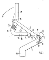
- Fig. 1 shows schematically how the seat 20 and the backrest 25 are connected to the adjusting device and which parts the adjusting device comprises.
- the column 10 of the chair frame merges into support arms 11 directed towards the front of the chair.
- pivot levers 13 are articulated on both sides of the seat, as the articulation axis 12 shows.
- the seat 20 is rotatably supported with a central area on bearing tabs 14 of the pivot lever 13.
- the seat 20 can have bearing brackets 23 which receive the bearing bolts for the axis of rotation 15.
- the free ends of the pivot levers 13 are connected to the backrest 25 as a fixed, non-rotatable connection point 16.
- the front region of the seat 20 carries bearing brackets 22 for the horizontal pivot axis 19.
- the carrying levers 17 are preferably pivotally mounted on the bearing brackets 22 on both sides of the seat 20, and are supported in an articulated manner on the support arms 11 via the axes of rotation 18.
- the axes of rotation 18 of the entraining lever 17 face the front end of the seat 20 and the pivot axis 13 of the pivot lever 13.
- the rear end of the seat 20 goes into the upward extension 21, which is connected to the lower end of the backrest 25 via the length compensation member 24.
- This length compensation member 24 has no load-bearing function, it merely covers the changing distance between the extension 21 of the seat 20 and the lower end of the backrest 25 in an elegant manner.
- the pivot levers 13 are also adjusted in the direction 27.
- the swivel angle of the swivel levers 13 is increased due to the distance between the axes of rotation 15 and the articulation axes 12.
- the entraining levers 17 perform a swiveling movement in the same direction, so that the seat 20, in addition to a lowering in the front region, also a displacement in the direction of the backrest 25 experiences.
- the backrest 25 executes the inclination movement 28, which is greater than the inclination movement of the seat 20. Since the connection point 16 is rigid, the backrest 25 is forcibly adjusted in the direction 29.
- the length compensation member 24 allows this movement.
- the length compensation member 24 takes on the adaptation of the changing distance between the lower end of the backrest 25 and the extension 21 of the seat 20th
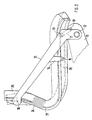
- Fig. 2 shows an embodiment of a chair on an enlarged scale.
- a swivel lever 13 and an entraining lever 17 are arranged on both sides of the seat 20.
- Two support arms 11 extend from the column of the chair frame, not shown, which extend to the front region of the seat 20.
- the seat 20 can consist of a seat support and seat cushion be composed.
- the pivot levers 13 initially go upward from the articulation axis 12 with an angled section and then extend inclinedly into the lower region of the backrest 25, which can also be composed of a backrest support and a backrest cushion.
- the ends of the pivot levers 13 are fixed and non-rotatably connected to the backrest 25, as the connection point 16 shows.
- downward-facing bearing brackets 14 are attached in the front area and run approximately parallel to the angled end sections of the swivel levers 13.
- About the middle region of the seat 20 is rotatably mounted on the bearing tabs 14, as the axis of rotation 15 shows.
- further mounting brackets are attached, on which the entraining levers 17 are pivotally mounted about the horizontal pivot axis 19.
- the driving levers 17 are articulated on the support arms 11 via the axes of rotation 18. In the starting position, the pivot axis 19 of the driving lever 17 and thus the horizontal pivot axis of the seat 20 lie above the pivot axis 12 of the pivot lever 13.
- the axes of rotation 18 of the pivot lever 17 face the front end of the seat 20 in front of the pivot axis 12 of the pivot lever 13. With the distance of the axes of rotation 15 from the articulation axes 12 is the measure of the increase in the angle of inclination of the backrest 25 when the seat 20 is lowered.
- the swivel levers 13 are also adjusted in the same swivel direction via the mounting brackets 14, the swivel angle of the swivel lever 13 being correspondingly greater than the swivel angle of the seat 20.
- the driving levers 17 are also pivoted in the direction of the backrest 25.
- the backrest 25 can be adjusted up to a 25 'marked end position, the seat 20 assuming the end position shown in broken lines in FIG. 3. The lowering of the front area of the seat 20 can be clearly seen.
- the pivot levers 13 are preferably designed as armrests or armrests and can be padded.
- the shape above the seat 20 can be designed freely if the rotary bearing of the seat 20 and the fixed attachment of the backrest 25 to the pivot levers 13 and the pivot bearing of the pivot lever 13 on the support arms 11 of the chair frame are maintained.
- the dimensioning of the driving lever 17 and its articulation on the seat 20 and the support arms 11 depends on the amount of the desired lowering of the front region of the seat 20 and the amount of the desired displacement of the seat 20 in the direction of the backrest 25.
- the arrangement of the adjusting device comprising the pivoting lever 13 and the carrying lever 17 is identical on both sides of the seat 20.
- the backrest 25 When the seat 20 is lowered, the backrest 25 is simultaneously also adjusted downwards via the pivoting lever 13, the distance between the lower end of the backrest 25 and the rear end of the seat 20 becoming smaller.
- This change in distance compensates for the length compensation member 24, which can be constructed in various ways.
- Two telescopic parts, which on the backrest 25 and the Seat 20 attached and covered by a bellows can take over the compensation.
- the same purpose is fulfilled by an elastic part which is designed in the manner of a bellows and is connected to the seat 20 and the backrest 25. A shapely transition can be achieved between the seat 20 and the backrest 25.
Landscapes
- Health & Medical Sciences (AREA)
- Dentistry (AREA)
- General Health & Medical Sciences (AREA)
- Chairs For Special Purposes, Such As Reclining Chairs (AREA)
- Chairs Characterized By Structure (AREA)
- Plural Heterocyclic Compounds (AREA)
Abstract
Description
- Die Erfindung betrifft einen Stuhl, insbesondere Arbeits- oder Bürostuhl, mit einem im vorderen Bereich um eine horizontale Schwenkachse schwenkbaren und in der Neigung veränderbaren Sitz und einem in Abhängigkeit von der Neigungsänderung des Sitzes mittels einer Verstelleinrichtung zwangsweise in der Neigung überproportional veränderbaren Rückenlehne, bei dem mit zunehmender Neigung des Sitzes die Rückenlehne gegenüber dem zugekehrten Ende des Sitzes eine zusätzliche Relativbewegung nach unten ausführt.
- Die bekannten Stühle dieser Art bieten einen ausgezeichneten Sitzkomfort, da sie einerseits in der Ausgangs- oder Arbeitsstellung dank der praktisch senkrechten Stellung der Rückenlehne ein eindeutiges Abstützen des Rückens des Benützers erbringen, andererseits aber nach dem Rückwärtsneigen der Rückenlehne ein entspanntes Sitzen ermöglichen. Beim Rückwärtsneigen der Rückenlehne macht der Oberkörper des Benützers nicht einfach eine Schwenkbewegung, sondern es ergibt sich eine aus verschiedenen Bewegungskomponenten überlagerte Bewegung. Da die Rückenlehne beim Rückwärtsneigen eine zusätzliche Abwärtsbewegung in Richtung zum Sitz ausführt, wird eine Relativbewegung zwischen dem Rücken des Benützers und der Rückenlehne vermieden oder zumindest auf einen nicht mehr bemerkbaren Wert reduziert.
- Wie die EP 0 085 670 A1, die EP 0 176 816 A1 und die DE 29 16 897 A1 zeigen, kann diese Kompensation der Relativbewegung zwischen dem Körper des Benützers und der Rückenlehne an verschiedenartigen Stühlen auf konstruktiv unterschiedliche Arten gelöst werden. Der Stuhl kann als Synchronstuhl ausgebildet sein, bei dem ein Abwärtsneigen des den Sitz tragenden Sitzträgers zwangsweise ein Rückwärtsneigen des Rückenlehnenstabes mit größerem Neigungswinkel bewirkt. Der Sitzträger mit dem Sitz kann auch an dem Lagerbock ausziehbar geführt sein. Wie diese bekannten Stühle zeigen, ist zur Kompensation der Relativbewegung zwischen dem Körper des Benützers und der Rückenlehne, die beim Verändern der Neigung des Rückenlehnenstabes auftritt, stets eine aufwendige und komplizierte Verstelleinrichtung erforderlich, die nicht immer störungsfrei und betriebssicher arbeitet.
- Dabei sind zum einen mehrgliedrige Hebelketten eingesetzt, wie die EP 0 176 816 A1 zeigt, oder zum anderen Übersetzungshebelpaare und Mitnehmerbögen wie die EP 0 085 870 A1 zeigt. In jedem Falle sind viele Teile für die Verstelleinrichtung erforderlich. Dasselbe gilt auch für einen Stuhl nach der DE 29 16 897 A1, bei der mit dem Herausziehen des Sitzes die Rückenlehne am Rückenlehnenstab in Richtung zum Sitz hin verschoben wird.
- Ein weiterer Nachteil dieser bekannten Stühle besteht darin, daß die Schwenk- oder Drehlager der Verstelleinrichtung teilweise eine zusätzliche Verstellbewegung der gelenkig miteinander verbundenen Teile zulassen müssen. Der Aufbau dieser Lager ist daher meist kompliziert und nicht absolut betriebssicher.
- Es ist Aufgabe der Erfindung, einen Stuhl der eingangs erwähnten Art zu schaffen, bei dem die Verstelleinrichtung sehr einfach ist und nur übliche Schwenk- und Drehlager ohne zusätzliche Verstellbewegung der gelenkig verbundenen Teile erfordert.
- Diese Aufgabe wird nach der Erfindung dadurch gelöst, daß zu beiden Seiten des Sitzes an Tragarmen des Stuhlgestelles Schwenkhebel angelenkt sind, deren freie Enden fest und unverdrehbar an der Rückenlehne angebracht sind und die Rückenlehne tragen und daß der Sitz etwa in seinem mittleren Bereich an den Schwenkhebeln drehbar gelagert und sich im vorderen Bereich über mindestens einen Mitführhebel gelenkig an dem Stuhlgestell abstützt.
- Die Schwenkhebel und der bzw. die Mitführhebel sind mittels üblicher Dreh- oder Schwenklager mit dem Stuhlgestell oder miteinander verbunden, so daß die Verstelleinrichtung absolut betriebssicher ausgelegt werden kann. Zwischen dem Sitz und der Rückenlehne besteht keine direkte Verbindung über die Verstelleinrichtung. Die Schwenkhebel tragen die Rückenlehne und verstellen diese zwangsweise. Durch die Wahl des Abstandes der Drehachsen des Sitzes von den Anlenkachsen der Schwenkhebel läßt sich die überproportionale Neigungsänderung der Rückenlehne beim Absenken des Sitzes festlegen.
- Aus optischen Gründen kann dabei vorgesehen sein, daß das untere Ende der Rückenlehne über ein Längenausgleichsglied mit dem hinteren Bereich des Sitzes verbunden ist, um einen formschönen Übergang zwischen der Rückenlehne und dem Sitz zu erreichen.
- Nach einer bevorzugten Ausgestaltung ist vorgesehen, daß die Schwenkhebel als Armlehnen oder Armstützen ausgebildet sind und somit eine weitere Funktion übernehmen.
- Der formschöne Übergang von dem Sitz zur Rückenlehne wird dabei dadurch noch verbessert, daß der Sitz am hinteren Ende eine nach oben gerichtete Verlängerung aufweist, die über das Längenausgleichsglied vorzugsweise formschlüssig mit dem unteren Ende der Rückenlehne verbunden ist.
- Ist das Längenausgleichsglied aus zwei teleskopierbaren Teilen gebildet, dann sind die beiden Teile mit dem Sitz und der Rückenlehne verbunden und mittels eines Faltenbalges abgedeckt. Eine tragende Funktion braucht das Längenausgleichsglied nicht zu übernehmen, es deckt nur den sich ändernden Abstand zwischen dem hinteren Bereich des Sitzes und dem unteren Ende der Rückenlehne ab.
- Das elastisch ausgebildete Längenausgleichsglied kann jedoch auch selbst als Faltenbalg ausgebildet sein.
- Die Drehlagerung des Sitzes an den Schwenkhebeln ist nach einer Ausgestaltung so gelöst, daß die Schwenkhebel zwischen der Anlenkachse an den Tragarmen und der festen Verbindungsstelle an der Rückenlehne nach unten ragende Lagerlaschen tragen, an denen der Sitz drehbar gelagert ist. Dabei kann der Sitz ebenfalls Lagerlaschen für die Lagerbolzen aufweisen oder selbst die Lagerbolzen tragen.
- Damit die als Armlehnen ausgebildeten Schwenkhebel über der Sitzfläche des Sitzes stehen, sieht eine Ausgestaltung vor, daß die Schwenkhebel im Bereich der Anlenkachse nach unten abgewinkelt sind und annähernd parallel zu den Lagerlaschen für den Sitz verlaufen.
- Beim Absenken des Sitzes wird der Sitz in Richtung zur Rückenlehne verschoben, wenn die Ausgestaltung so ist, daß die Anlenkachse der Schwenkhebel unterhalb der horizontalen Schwenkachse des vorderen Bereiches des Sitzes angeordnet ist, und daß die Drehachse des bzw. der Mitführhebel an den Tragarmen dem vorderen Ende des Sitzes zugekehrt vor der Anlenkachse der Schwenkhebel angeordnet ist.
- Die Erfindung wird anhand eines in den Zeichnungen dargestellten Ausführungsbeispiels näher erläutert. Es zeigt:
- Fig. 1 schematisch in Seitenansicht den Stuhl mit der Verstelleinrichtung in der Ausgangsstellung,
- Fig. 2 in vergrößertem Maßstab die Verstelleinrichtung und den Stuhl gemäß einer Ausgestaltung in derselben Seitenansicht und
- Fig. 3 die andere Seitenansicht des Stuhles nach Fig. 2 bei abgesenktem Sitz und zurückgeneigter Rückenlehne.
- Die Fig. 1 zeigt schematisch, wie der Sitz 20 und die Rückenlehne 25 mit der Verstelleinrichtung verbunden sind und welche Teile die Verstelleinrichtung umfaßt. Die Säule 10 des Stuhlgestelles geht in zur Vorderseite des Stuhles gerichtete Tragarme 11 über. Am Ende der Tragarme 11 sind zu beiden Seiten des Sitzes 20 Schwenkhebel 13 angelenkt, wie die Anlenkachse 12 zeigt. Der Sitz 20 ist mit einem mittleren Bereich an Lagerlaschen 14 der Schwenkhebel 13 drehbar gelagert. Dabei kann der Sitz 20 Lagerlaschen 23 aufweisen, die die Lagerbolzen für die Drehachse 15 aufnehmen. Die freien Enden der Schwenkhebel 13 sind als feste unverdrehbare Verbindungsstelle 16 mit der Rückenlehne 25 verbunden. Der vordere Bereich des Sitzes 20 trägt Lagerlaschen 22 für die horizontale Schwenkachse 19. An den Lagerlaschen 22 sind vorzugsweise auch zu beiden Seiten des Sitzes 20 die Mitführhebel 17 schwenkbar gelagert, die sich über die Drehachsen 18 gelenkig an den Tragarmen 11 abstützen. Die Drehachsen 18 der Mitführhebel 17 liegen dem vorderen Ende des Sitzes 20 zugekehrt von der Anlenkachse 12 der Schwenkhebel 13. Das hintere Ende des Sitzes 20 geht in die nach oben gerichtete Verlängerung 21 über, die über das Längenausgleichsglied 24 mit dem unteren Ende der Rückenlehne 25 in Verbindung steht. Dieses Längenausgleichsglied 24 hat keine tragende Funktion, es deckt lediglich den sich ändernden Abstand zwischen der Verlängerung 21 des Sitzes 20 und dem unteren Ende der Rückenlehne 25 formschön ab.
- Wird der Sitz 20 in Richtung 26 nach unten verstellt, dann werden die Schwenkhebel 13 in Richtung 27 mit verstellt. Dabei wird der Schwenkwinkel der Schwenkhebel 13 vergrößert, bedingt durch den Abstand der Drehachsen 15 von den Anlenkachsen 12. Die Mitführhebel 17 führen eine gleichgerichtete Schwenkbewegung aus, so daß der Sitz 20 neben einer Absenkung im vorderen Bereich auch noch eine Verschiebung in Richtung zur Rückenlehne 25 erfährt. Die Rückenlehne 25 führt die Neigungsbewegung 28 aus, die größer ist als die Neigungsbewegung des Sitzes 20. Da die Verbindungsstelle 16 starr ist, wird die Rückenlehne 25 zwangsweise in Richtung 29 verstellt. Das Längenausgleichsglied 24 läßt diese Bewegung zu. Damit wird erreicht, daß mit zunehmender Neigung der Rückenlehne 25 eine Absenkbewegung 29 der Rückenlehne 25 in Richtung zum Sitz 20 ausgeführt wird. Das Längenausgleichsglied 24 übernimmt die Anpassung des sich ändernden Abstandes zwischen dem unteren Ende der Rückenlehne 25 und der Verlängerung 21 des Sitzes 20.
- Fig. 2 zeigt in vergrößertem Maßstab ein Ausführungsbeispiel eines Stuhles. Zu beiden Seiten des Sitzes 20 ist ein Schwenkhebel 13 und ein Mitführhebel 17 angeordnet. Von der nicht dargestellten Säule des Stuhlgestelles gehen zwei Tragarme 11 aus, die sich bis zum vorderen Bereich des Sitzes 20 erstrecken. Der Sitz 20 kann aus Sitzträger und Sitzpolster zusammengesetzt sein. Die Schwenkhebel 13 gehen von der Anlenkachse 12 zunächst mit einem abgewinkelten Abschnitt nach oben und erstrecken sich dann geneigt bis in den unteren Bereich der Rückenlehne 25, die ebenfalls aus einem Rückenlehnenträger und einem Rückenlehnenpolster zusammengesetzt sein kann. Die Enden der Schwenkhebel 13 sind fest und unverdrehbar mit der Rückenlehne 25 verbunden, wie die Verbindungsstelle 16 zeigt. An den Schwenkhebeln 13 sind im vorderen Bereich nach unten gerichtete Lagerlaschen 14 angebracht, die annähernd parallel zu den abgewinkelten Endabschnitten der Schwenkhebel 13 verlaufen. An den Lagerlaschen 14 ist etwa der mittlere Bereich des Sitzes 20 drehbar gelagert, wie die Drehachse 15 zeigt. Im vorderen Bereich des Sitzes 20 sind weitere Lagerlaschen angebracht, an denen die Mitführhebel 17 um die horizontale Schwenkachse 19 schwenkbar gelagert sind. Die Mitführhebel 17 stützen sich über die Drehachsen 18 an den Tragarmen 11 gelenkig ab. Dabei liegt in der Ausgangsstellung die Schwenkachse 19 des Mitführhebels 17 und damit die horizontale Schwenkachse des Sitzes 20 über der Anlenkachse 12 der Schwenkhebel 13. Die Drehachsen 18 der Mitführhebel 17 liegen dem vorderen Ende des Sitzes 20 zugekehrt vor der Anlenkachse 12 der Schwenkhebel 13. Mit dem Abstand der Drehachsen 15 von den Anlenkachsen 12 wird das Maß der Vergrößerung des Neigungswinkels der Rückenlehne 25 beim Absenken des Sitzes 20 festgelegt. Beim Absenken des Sitzes 20 werden über die Lagerlaschen 14 die Schwenkhebel 13 in gleicher Schwenkrichtung mit verstellt, wobei der Schwenkwinkel der Schwenkhebel 13 entsprechend größer ist als der Schwenkwinkel des Sitzes 20.
- Wie die Ansicht nach Fig. 3 zeigt, werden dabei die Mitführhebel 17 in Richtung zur Rückenlehne 25 mit verschwenkt. Dies führt zum Absenken des vorderen Bereiches des Sitzes 20, verbunden mit einer Verschiebung des Sitzes 20 in Richtung zur Rückenlehne 25, was den Sitzkomfort des Stuhles auch bei abgesenktem Sitz 20 verbessert. Die Rückenlehne 25 kann bis zu einer mit 25′ gekennzeichneten Endstellung verstellt werden, wobei der Sitz 20 die in Fig. 3 gestrichelt eingezeichnete Endstellung einnimmt. Dabei ist deutlich die Absenkung des vorderen Bereiches des Sitzes 20 zu erkennen.
- Die Schwenkhebel 13 werden vorzugsweise als Armlehnen oder Armstützen ausgebildet und können eine Polsterung tragen. Dabei kann die Form über dem Sitz 20 frei gestaltet werden, wenn die Drehlagerung des Sitzes 20 und die feste Anbringung der Rückenlehne 25 an den Schwenkhebeln 13 sowie die Schwenklagerung der Schwenkhebel 13 an den Tragarmen 11 des Stuhlgestelles beibehalten werden. Die Dimensionierung der Mitführhebel 17 und ihre Anlenkung an dem Sitz 20 und den Tragarmen 11 richtet sich nach dem Betrag der gewünschten Absenkung des vorderen Bereiches des Sitzes 20 und dem Betrag der gewünschten Verschiebung des Sitzes 20 in Richtung zur Rückenlehne 25.
- Wie die Seitenansichten nach Fig. 2 und 3 erkennen lassen, ist die Anordnung der Verstelleinrichtung aus Schwenkhebel 13 und Mitführhebel 17 auf beiden Seiten des Sitzes 20 identisch.
- Beim Absenken des Sitzes 20 wird die Rückenlehne 25 über die Schwenkhebel 13 gleichzeitig auch nach unten verstellt, wobei der Abstand des unteren Endes der Rückenlehne 25 zum hinteren Ende des Sitzes 20 kleiner wird. Diese Abstandsänderung gleicht das Längenausgleichsglied 24 aus, das auf verschiedene Art aufgebaut sein kann. Zwei teleskopierbare Teile, die an der Rückenlehne 25 und dem Sitz 20 befestigt und mittels eines Faltenbalges abgedeckt sind, können den Ausgleich übernehmen. Denselben Zweck erfüllt ein elastisches Teil, das selbst nach Art eines Faltenbalges ausgelegt und mit dem Sitz 20 und der Rückenlehne 25 verbunden ist. Dabei läßt sich ein formschöner Übergang zwischen dem Sitz 20 und der Rückenlehne 25 erreichen.
Claims (10)
dadurch gekennzeichnet,
daß zu beiden Seiten des Sitzes (20) an Tragarmen (11) des Stuhlgestelles Schwenkhebel (13) angelenkt sind, deren freie Enden fest und unverdrehbar an der Rückenlehne (25) angebracht sind und die Rückenlehne (25) tragen und,
daß der Sitz (20) etwa in seinem mittleren Bereich an den Schwenkhebeln (13) drehbar gelagert ist und sich im vorderen Bereich über mindestens einen Mitführhebel (17) gelenkig an dem Stuhlgestell abstützt.
dadurch gekennzeichnet,
daß das untere Ende der Rückenlehne (25) über ein Längenausgleichsglied (24) mit dem hinteren Bereich des Sitzes (20) verbunden ist.
dadurch gekennzeichnet,
daß die Schwenkhebel (13) als Armlehnen oder Armstützen ausgebildet sind.
dadurch gekennzeichnet,
daß der Sitz (20) am hinteren Ende eine nach oben gerichtete Verlängerung (21) aufweist, die über das Längenausgleichsglied (24) vorzugsweise formschlüssig mit dem unteren Ende der Rückenlehne (25) verbunden ist.
dadurch gekennzeichnet,
daß das Längenausgleichsglied (24) zwei teleskopierbare Teile aufweist, die mit dem Sitz (20) und der Rückenlehne (25) verbunden und mittels eines Faltenbalges abgedeckt sind.
dadurch gekennzeichnet,
daß das Längenausgleichsglied (24) selbst elastisch ausgebildet ist und die Form eines Faltenbalges aufweist.
dadurch gekennzeichnet,
daß die Schwenkhebel (13) zwischen der Anlenkachse (12) an den Tragarmen (11) und der festen Verbindungsstelle (16) an der Rückenlehne (25) nach unten ragende Lagerlaschen (14) tragen, an denen der Sitz (20) drehbar gelagert ist.
dadurch gekennzeichnet,
daß die Schwenkhebel (13) im Bereich der Anlenkachse (12) nach unten abgewinkelt sind und annähernd parallel zu den Lagerlaschen (14) für den Sitz (20) verlaufen.
dadurch gekennzeichnet,
daß die Anlenkachse (12) der Schwenkhebel (13) unterhalb der horizontalen Schwenkachse (19) des vorderen Bereiches des Sitzes (20) angeordnet ist.
dadurch gekennzeichnet,
daß die Drehachse (18) des bzw. der Mitführhebel (17) an den Tragarmen (11) dem vorderen Ende des Sitzes (20) zugekehrt vor der Anlenkachse (12) der Schwenkhebel (13) angeordnet ist.
Priority Applications (1)
| Application Number | Priority Date | Filing Date | Title |
|---|---|---|---|
| AT89108563T ATE75114T1 (de) | 1988-05-26 | 1989-05-12 | Stuhl, insbesondere arbeits- oder buerostuhl. |
Applications Claiming Priority (2)
| Application Number | Priority Date | Filing Date | Title |
|---|---|---|---|
| DE3817761A DE3817761A1 (de) | 1988-05-19 | 1988-05-26 | Stuhl, insbesondere arbeits- oder buerostuhl |
| DE3817761 | 1988-05-26 |
Publications (2)
| Publication Number | Publication Date |
|---|---|
| EP0343450A1 true EP0343450A1 (de) | 1989-11-29 |
| EP0343450B1 EP0343450B1 (de) | 1992-04-22 |
Family
ID=6355087
Family Applications (1)
| Application Number | Title | Priority Date | Filing Date |
|---|---|---|---|
| EP89108563A Expired - Lifetime EP0343450B1 (de) | 1988-05-26 | 1989-05-12 | Stuhl, insbesondere Arbeits- oder Bürostuhl |
Country Status (7)
| Country | Link |
|---|---|
| US (1) | US5071189A (de) |
| EP (1) | EP0343450B1 (de) |
| JP (1) | JPH02191410A (de) |
| AT (1) | ATE75114T1 (de) |
| CA (1) | CA1320676C (de) |
| DE (2) | DE3817761A1 (de) |
| ES (1) | ES2032626T3 (de) |
Cited By (1)
| Publication number | Priority date | Publication date | Assignee | Title |
|---|---|---|---|---|
| EP2100539A1 (de) * | 2008-03-10 | 2009-09-16 | Savo AS | Rückenlehnenvorrichtung |
Families Citing this family (27)
| Publication number | Priority date | Publication date | Assignee | Title |
|---|---|---|---|---|
| BR9306555A (pt) | 1992-06-15 | 1998-09-15 | Miller Herman Inc | Cadeira de escritório |
| IL103477A0 (en) * | 1992-10-20 | 1993-03-15 | Paltechnica Nitzanim | Office and like chairs |
| DE29612594U1 (de) * | 1996-07-20 | 1996-09-19 | Franck, Klaus-Reiner, 30449 Hannover | Vorrichtung zur Synchronanpassung von Sitz- und Rückenlehne eines Stuhles an die Körperhaltung eines Benutzers |
| DE10026475A1 (de) * | 2000-05-27 | 2001-12-06 | Haworth Bueroeinrichtung Gmbh | Stuhl |
| IT1315528B1 (it) * | 2000-10-18 | 2003-02-18 | Enrico Cioncada | Poltrona ad assetto variabile |
| US6644741B2 (en) | 2001-09-20 | 2003-11-11 | Haworth, Inc. | Chair |
| US20030132653A1 (en) * | 2001-10-18 | 2003-07-17 | Doug Thole | Tension control mechanism for a chair |
| US7040703B2 (en) | 2002-03-29 | 2006-05-09 | Garrex Llc | Health chair a dynamically balanced task chair |
| US7396082B2 (en) | 2002-03-29 | 2008-07-08 | Garrex Llc | Task chair |
| US7625046B2 (en) | 2002-03-29 | 2009-12-01 | Garrex Llc | Task chair |
| US6945602B2 (en) * | 2003-12-18 | 2005-09-20 | Haworth, Inc. | Tilt control mechanism for chair |
| US20070090671A1 (en) * | 2005-10-06 | 2007-04-26 | Rbm A/S; | Weight regulator for a chair |
| US9777111B2 (en) * | 2005-10-20 | 2017-10-03 | Grupo Petrotemex, S.A. De C.V. | PET polymer with improved properties |
| US7806478B1 (en) * | 2006-01-04 | 2010-10-05 | Sava Cvek | Task chair with dual tilting capabilities |
| BRPI0823267A2 (pt) | 2007-01-29 | 2013-09-24 | Miller Herman Inc | estrutura de assento e mÉtodos para uso da mesma |
| DE202009014380U1 (de) * | 2009-10-23 | 2010-04-01 | GLÖCKL, Josef | Stehsitz |
| US20110304192A1 (en) * | 2010-06-15 | 2011-12-15 | Augustat Betty A | Ergometric Chair Apparatus |
| US9706845B2 (en) | 2012-09-20 | 2017-07-18 | Steelcase Inc. | Chair assembly |
| US11304528B2 (en) | 2012-09-20 | 2022-04-19 | Steelcase Inc. | Chair assembly with upholstery covering |
| USD697726S1 (en) | 2012-09-20 | 2014-01-21 | Steelcase Inc. | Chair |
| US9801471B2 (en) | 2014-04-17 | 2017-10-31 | Hni Technologies Inc. | Chair and chair control assemblies, systems, and methods |
| MY206922A (en) | 2015-04-13 | 2025-01-17 | Steelcase Inc | Seating arrangement |
| US10194750B2 (en) | 2015-04-13 | 2019-02-05 | Steelcase Inc. | Seating arrangement |
| US11259637B2 (en) | 2015-04-13 | 2022-03-01 | Steelcase Inc. | Seating arrangement |
| AU2020224628B2 (en) | 2019-02-21 | 2025-04-24 | Steelcase Inc. | Body support assembly and methods for the use and assembly thereof |
| JPWO2020255195A1 (de) * | 2019-06-17 | 2020-12-24 | ||
| US11357329B2 (en) | 2019-12-13 | 2022-06-14 | Steelcase Inc. | Body support assembly and methods for the use and assembly thereof |
Citations (4)
| Publication number | Priority date | Publication date | Assignee | Title |
|---|---|---|---|---|
| EP0063860A2 (de) * | 1981-04-29 | 1982-11-03 | Hauserman Inc. | Stuhl |
| DE3322450A1 (de) * | 1983-06-22 | 1985-01-10 | August Fröscher GmbH & Co KG, 7141 Steinheim | Vorrichtung zum verstellen des sitzes und der rueckenlehne von stuehlen |
| EP0179357A2 (de) * | 1984-10-23 | 1986-04-30 | Protoned B.V. | Sitzmöbel |
| DE8616836U1 (de) * | 1986-06-24 | 1987-10-22 | Hartmann, Günter, 5800 Hagen | Sitzmöbel, insbesondere Stuhl |
Family Cites Families (13)
| Publication number | Priority date | Publication date | Assignee | Title |
|---|---|---|---|---|
| US2433521A (en) * | 1945-03-01 | 1947-12-30 | Lorenz Anton | Reclining article of furniture |
| AU541109B2 (en) * | 1981-08-19 | 1984-12-13 | Giroflex Entwicklungs Ag | Chair |
| DE3232771A1 (de) * | 1982-09-03 | 1984-03-08 | Wilkhahn Wilkening + Hahne GmbH + Co, 3252 Bad Münder | Arbeits-sitzmoebel |
| US4560199A (en) * | 1983-07-22 | 1985-12-24 | Pamont Ag | Recliner chair |
| DE8326792U1 (de) * | 1983-09-17 | 1984-01-05 | Fromme, Heinrich, 4815 Schloß Holte-Stukenbrock | Stuhl, insbesondere drehstuhl |
| DE3608718A1 (de) * | 1986-03-15 | 1987-09-17 | Drabert Soehne | Sitzmoebel |
| DE8614186U1 (de) * | 1986-05-26 | 1986-07-17 | Drabert Söhne GmbH & Co, 4950 Minden | Stuhl |
| DE3632131C2 (de) * | 1986-06-04 | 2001-12-13 | Hartmut S Engel | Funktions-Sitzmöbel |
| DE3622272A1 (de) * | 1986-07-03 | 1988-01-21 | Porsche Ag | Stuhl, insbesondere buerostuhl |
| DE3630503A1 (de) * | 1986-09-08 | 1988-03-10 | Girsberger Holding Ag | Stuhl |
| DE3635044A1 (de) * | 1986-10-15 | 1988-04-28 | Rolf Voelkle | Sessel |
| DE3642796A1 (de) * | 1986-12-15 | 1988-06-23 | Eckhard Hansen | Punktsynchronverstelleinrichtung fuer buerostuehle, sitzmoebel o. dgl. |
| DE3737491C2 (de) * | 1987-11-05 | 2003-03-20 | Wilkhahn Wilkening & Hahne | Stuhl |
-
1988
- 1988-05-26 DE DE3817761A patent/DE3817761A1/de active Granted
-
1989
- 1989-05-12 AT AT89108563T patent/ATE75114T1/de not_active IP Right Cessation
- 1989-05-12 EP EP89108563A patent/EP0343450B1/de not_active Expired - Lifetime
- 1989-05-12 ES ES198989108563T patent/ES2032626T3/es not_active Expired - Lifetime
- 1989-05-12 DE DE8989108563T patent/DE58901223D1/de not_active Expired - Fee Related
- 1989-05-25 JP JP1130307A patent/JPH02191410A/ja active Pending
- 1989-05-25 CA CA000600701A patent/CA1320676C/en not_active Expired - Fee Related
-
1990
- 1990-10-31 US US07/606,873 patent/US5071189A/en not_active Expired - Fee Related
Patent Citations (4)
| Publication number | Priority date | Publication date | Assignee | Title |
|---|---|---|---|---|
| EP0063860A2 (de) * | 1981-04-29 | 1982-11-03 | Hauserman Inc. | Stuhl |
| DE3322450A1 (de) * | 1983-06-22 | 1985-01-10 | August Fröscher GmbH & Co KG, 7141 Steinheim | Vorrichtung zum verstellen des sitzes und der rueckenlehne von stuehlen |
| EP0179357A2 (de) * | 1984-10-23 | 1986-04-30 | Protoned B.V. | Sitzmöbel |
| DE8616836U1 (de) * | 1986-06-24 | 1987-10-22 | Hartmann, Günter, 5800 Hagen | Sitzmöbel, insbesondere Stuhl |
Cited By (1)
| Publication number | Priority date | Publication date | Assignee | Title |
|---|---|---|---|---|
| EP2100539A1 (de) * | 2008-03-10 | 2009-09-16 | Savo AS | Rückenlehnenvorrichtung |
Also Published As
| Publication number | Publication date |
|---|---|
| CA1320676C (en) | 1993-07-27 |
| JPH02191410A (ja) | 1990-07-27 |
| DE3817761C2 (de) | 1990-05-10 |
| US5071189A (en) | 1991-12-10 |
| DE58901223D1 (de) | 1992-05-27 |
| ATE75114T1 (de) | 1992-05-15 |
| EP0343450B1 (de) | 1992-04-22 |
| DE3817761A1 (de) | 1989-11-30 |
| ES2032626T3 (es) | 1993-02-16 |
Similar Documents
| Publication | Publication Date | Title |
|---|---|---|
| EP0343450B1 (de) | Stuhl, insbesondere Arbeits- oder Bürostuhl | |
| DE19930922B4 (de) | Stuhl | |
| DE3916474C2 (de) | ||
| DE60300064T2 (de) | Stuhl mit beweglichem Sitz und Rückenlehne | |
| DE10026475A1 (de) | Stuhl | |
| DE10122948C1 (de) | Stuhl, insbesondere Bürostuhl | |
| AT402602B (de) | Stuhl stuhl | |
| EP1256293B1 (de) | Stuhl, insbesondere Bürostuhl | |
| EP0176816A1 (de) | Stuhl mit rückwärts neigbarem Sitz- und Rückenlehnenträger | |
| DE3534496A1 (de) | Sitzmoebel | |
| DE3744365A1 (de) | Stuhl, insbesondere arbeits- oder buerostuhl | |
| EP1906792A1 (de) | Stuhl, insbesondere bürostuhl | |
| DE60200399T2 (de) | Sitzmöbel mit einem Sitz und einer Rückenlehne | |
| DE3520188C2 (de) | Punktsynchronverstelleinrichtung für Bürostühle | |
| DE102007021782B3 (de) | Synchronmechanik für Bürostühle | |
| EP0559185A1 (de) | Synchronverstelleinrichtung für Bürostühle | |
| DE102005029906B3 (de) | Synchronmechanik | |
| EP1632152A2 (de) | Sitzmöbel | |
| DE3834614A1 (de) | Funktionssitzmoebel | |
| DE8806835U1 (de) | Stuhl, insbesondere Arbeits- oder Bürostuhl | |
| EP0372232B1 (de) | Stuhl, insbesondere Arbeits- oder Bürostuhl | |
| DE102010046994B4 (de) | Synchronmechanik | |
| EP1683441A1 (de) | Synchronmechanik | |
| EP0332088B1 (de) | Stuhl, insbesondere Arbeits und Bürostuhl | |
| DE29609389U1 (de) | Sitzmöbel mit ausschwenkbarer Fußstütze |
Legal Events
| Date | Code | Title | Description |
|---|---|---|---|
| PUAI | Public reference made under article 153(3) epc to a published international application that has entered the european phase |
Free format text: ORIGINAL CODE: 0009012 |
|
| AK | Designated contracting states |
Kind code of ref document: A1 Designated state(s): AT BE CH DE ES FR GB GR IT LI LU NL SE |
|
| 17P | Request for examination filed |
Effective date: 19891027 |
|
| 17Q | First examination report despatched |
Effective date: 19900223 |
|
| ITF | It: translation for a ep patent filed | ||
| GRAA | (expected) grant |
Free format text: ORIGINAL CODE: 0009210 |
|
| AK | Designated contracting states |
Kind code of ref document: B1 Designated state(s): AT BE CH DE ES FR GB GR IT LI LU NL SE |
|
| PG25 | Lapsed in a contracting state [announced via postgrant information from national office to epo] |
Ref country code: SE Effective date: 19920422 Ref country code: GR Free format text: LAPSE BECAUSE OF FAILURE TO SUBMIT A TRANSLATION OF THE DESCRIPTION OR TO PAY THE FEE WITHIN THE PRESCRIBED TIME-LIMIT Effective date: 19920422 |
|
| REF | Corresponds to: |
Ref document number: 75114 Country of ref document: AT Date of ref document: 19920515 Kind code of ref document: T |
|
| PG25 | Lapsed in a contracting state [announced via postgrant information from national office to epo] |
Ref country code: AT Effective date: 19920512 |
|
| REF | Corresponds to: |
Ref document number: 58901223 Country of ref document: DE Date of ref document: 19920527 |
|
| GBT | Gb: translation of ep patent filed (gb section 77(6)(a)/1977) | ||
| ET | Fr: translation filed | ||
| REG | Reference to a national code |
Ref country code: ES Ref legal event code: FG2A Ref document number: 2032626 Country of ref document: ES Kind code of ref document: T3 |
|
| PLBE | No opposition filed within time limit |
Free format text: ORIGINAL CODE: 0009261 |
|
| STAA | Information on the status of an ep patent application or granted ep patent |
Free format text: STATUS: NO OPPOSITION FILED WITHIN TIME LIMIT |
|
| 26N | No opposition filed | ||
| EPTA | Lu: last paid annual fee | ||
| REG | Reference to a national code |
Ref country code: CH Ref legal event code: PUE Owner name: ROEDER GMBH TRANSFER- HAWORTH BUEROEINRICHTUNGEN G |
|
| NLS | Nl: assignments of ep-patents |
Owner name: HAWORTH BUROEINRICHTUNGEN GMBH |
|
| PGFP | Annual fee paid to national office [announced via postgrant information from national office to epo] |
Ref country code: LU Payment date: 20000825 Year of fee payment: 12 |
|
| PGFP | Annual fee paid to national office [announced via postgrant information from national office to epo] |
Ref country code: ES Payment date: 20010315 Year of fee payment: 13 |
|
| PG25 | Lapsed in a contracting state [announced via postgrant information from national office to epo] |
Ref country code: LU Free format text: LAPSE BECAUSE OF NON-PAYMENT OF DUE FEES Effective date: 20010512 |
|
| PGFP | Annual fee paid to national office [announced via postgrant information from national office to epo] |
Ref country code: NL Payment date: 20010531 Year of fee payment: 13 |
|
| PGFP | Annual fee paid to national office [announced via postgrant information from national office to epo] |
Ref country code: DE Payment date: 20010606 Year of fee payment: 13 |
|
| PGFP | Annual fee paid to national office [announced via postgrant information from national office to epo] |
Ref country code: FR Payment date: 20010629 Year of fee payment: 13 |
|
| BERE | Be: lapsed |
Owner name: ROEDER G.M.B.H. Effective date: 20010531 |
|
| REG | Reference to a national code |
Ref country code: GB Ref legal event code: IF02 |
|
| PGFP | Annual fee paid to national office [announced via postgrant information from national office to epo] |
Ref country code: BE Payment date: 20020429 Year of fee payment: 14 |
|
| PGFP | Annual fee paid to national office [announced via postgrant information from national office to epo] |
Ref country code: GB Payment date: 20020510 Year of fee payment: 14 |
|
| PG25 | Lapsed in a contracting state [announced via postgrant information from national office to epo] |
Ref country code: ES Free format text: LAPSE BECAUSE OF NON-PAYMENT OF DUE FEES Effective date: 20020513 |
|
| PGFP | Annual fee paid to national office [announced via postgrant information from national office to epo] |
Ref country code: CH Payment date: 20020828 Year of fee payment: 14 |
|
| PG25 | Lapsed in a contracting state [announced via postgrant information from national office to epo] |
Ref country code: NL Free format text: LAPSE BECAUSE OF NON-PAYMENT OF DUE FEES Effective date: 20021201 |
|
| PG25 | Lapsed in a contracting state [announced via postgrant information from national office to epo] |
Ref country code: DE Free format text: LAPSE BECAUSE OF NON-PAYMENT OF DUE FEES Effective date: 20021203 |
|
| BERR | Be: reestablished |
Owner name: *ROEDER G.M.B.H. Effective date: 20020405 |
|
| NLV4 | Nl: lapsed or anulled due to non-payment of the annual fee |
Effective date: 20021201 |
|
| PG25 | Lapsed in a contracting state [announced via postgrant information from national office to epo] |
Ref country code: FR Free format text: LAPSE BECAUSE OF NON-PAYMENT OF DUE FEES Effective date: 20030331 |
|
| REG | Reference to a national code |
Ref country code: FR Ref legal event code: ST |
|
| PG25 | Lapsed in a contracting state [announced via postgrant information from national office to epo] |
Ref country code: GB Free format text: LAPSE BECAUSE OF NON-PAYMENT OF DUE FEES Effective date: 20030512 |
|
| PG25 | Lapsed in a contracting state [announced via postgrant information from national office to epo] |
Ref country code: CH Free format text: LAPSE BECAUSE OF NON-PAYMENT OF DUE FEES Effective date: 20030531 Ref country code: BE Free format text: LAPSE BECAUSE OF NON-PAYMENT OF DUE FEES Effective date: 20030531 Ref country code: LI Free format text: LAPSE BECAUSE OF NON-PAYMENT OF DUE FEES Effective date: 20030531 |
|
| BERE | Be: lapsed |
Owner name: *ROEDER G.M.B.H. Effective date: 20030531 |
|
| GBPC | Gb: european patent ceased through non-payment of renewal fee |
Effective date: 20030512 |
|
| REG | Reference to a national code |
Ref country code: CH Ref legal event code: PL |
|
| REG | Reference to a national code |
Ref country code: ES Ref legal event code: FD2A Effective date: 20030611 |
|
| PG25 | Lapsed in a contracting state [announced via postgrant information from national office to epo] |
Ref country code: IT Free format text: LAPSE BECAUSE OF NON-PAYMENT OF DUE FEES;WARNING: LAPSES OF ITALIAN PATENTS WITH EFFECTIVE DATE BEFORE 2007 MAY HAVE OCCURRED AT ANY TIME BEFORE 2007. THE CORRECT EFFECTIVE DATE MAY BE DIFFERENT FROM THE ONE RECORDED. Effective date: 20050512 |
|
| PG25 | Lapsed in a contracting state [announced via postgrant information from national office to epo] |
Ref country code: FR Free format text: LAPSE BECAUSE OF NON-PAYMENT OF DUE FEES Effective date: 20020531 |