EP0342704B1 - Bilderzeugungsgerät - Google Patents
Bilderzeugungsgerät Download PDFInfo
- Publication number
- EP0342704B1 EP0342704B1 EP89109090A EP89109090A EP0342704B1 EP 0342704 B1 EP0342704 B1 EP 0342704B1 EP 89109090 A EP89109090 A EP 89109090A EP 89109090 A EP89109090 A EP 89109090A EP 0342704 B1 EP0342704 B1 EP 0342704B1
- Authority
- EP
- European Patent Office
- Prior art keywords
- sheet
- feeding
- sheets
- conveying
- image forming
- Prior art date
- Legal status (The legal status is an assumption and is not a legal conclusion. Google has not performed a legal analysis and makes no representation as to the accuracy of the status listed.)
- Expired - Lifetime
Links
Images


Classifications
-
- G—PHYSICS
- G03—PHOTOGRAPHY; CINEMATOGRAPHY; ANALOGOUS TECHNIQUES USING WAVES OTHER THAN OPTICAL WAVES; ELECTROGRAPHY; HOLOGRAPHY
- G03G—ELECTROGRAPHY; ELECTROPHOTOGRAPHY; MAGNETOGRAPHY
- G03G15/00—Apparatus for electrographic processes using a charge pattern
- G03G15/65—Apparatus which relate to the handling of copy material
- G03G15/6555—Handling of sheet copy material taking place in a specific part of the copy material feeding path
- G03G15/6579—Refeeding path for composite copying
-
- G—PHYSICS
- G03—PHOTOGRAPHY; CINEMATOGRAPHY; ANALOGOUS TECHNIQUES USING WAVES OTHER THAN OPTICAL WAVES; ELECTROGRAPHY; HOLOGRAPHY
- G03G—ELECTROGRAPHY; ELECTROPHOTOGRAPHY; MAGNETOGRAPHY
- G03G15/00—Apparatus for electrographic processes using a charge pattern
- G03G15/01—Apparatus for electrographic processes using a charge pattern for producing multicoloured copies
- G03G15/0105—Details of unit
- G03G15/0121—Details of unit for developing
-
- G—PHYSICS
- G03—PHOTOGRAPHY; CINEMATOGRAPHY; ANALOGOUS TECHNIQUES USING WAVES OTHER THAN OPTICAL WAVES; ELECTROGRAPHY; HOLOGRAPHY
- G03G—ELECTROGRAPHY; ELECTROPHOTOGRAPHY; MAGNETOGRAPHY
- G03G15/00—Apparatus for electrographic processes using a charge pattern
- G03G15/01—Apparatus for electrographic processes using a charge pattern for producing multicoloured copies
- G03G15/0142—Structure of complete machines
- G03G15/0147—Structure of complete machines using a single reusable electrographic recording member
- G03G15/0152—Structure of complete machines using a single reusable electrographic recording member onto which the monocolour toner images are superposed before common transfer from the recording member
- G03G15/0163—Structure of complete machines using a single reusable electrographic recording member onto which the monocolour toner images are superposed before common transfer from the recording member primary transfer to the final recording medium
-
- G—PHYSICS
- G03—PHOTOGRAPHY; CINEMATOGRAPHY; ANALOGOUS TECHNIQUES USING WAVES OTHER THAN OPTICAL WAVES; ELECTROGRAPHY; HOLOGRAPHY
- G03G—ELECTROGRAPHY; ELECTROPHOTOGRAPHY; MAGNETOGRAPHY
- G03G15/00—Apparatus for electrographic processes using a charge pattern
- G03G15/22—Apparatus for electrographic processes using a charge pattern involving the combination of more than one step according to groups G03G13/02 - G03G13/20
- G03G15/23—Apparatus for electrographic processes using a charge pattern involving the combination of more than one step according to groups G03G13/02 - G03G13/20 specially adapted for copying both sides of an original or for copying on both sides of a recording or image-receiving material
- G03G15/231—Arrangements for copying on both sides of a recording or image-receiving material
- G03G15/232—Arrangements for copying on both sides of a recording or image-receiving material using a single reusable electrographic recording member
- G03G15/234—Arrangements for copying on both sides of a recording or image-receiving material using a single reusable electrographic recording member by inverting and refeeding the image receiving material with an image on one face to the recording member to transfer a second image on its second face, e.g. by using a duplex tray; Details of duplex trays or inverters
-
- G—PHYSICS
- G03—PHOTOGRAPHY; CINEMATOGRAPHY; ANALOGOUS TECHNIQUES USING WAVES OTHER THAN OPTICAL WAVES; ELECTROGRAPHY; HOLOGRAPHY
- G03G—ELECTROGRAPHY; ELECTROPHOTOGRAPHY; MAGNETOGRAPHY
- G03G2215/00—Apparatus for electrophotographic processes
- G03G2215/00362—Apparatus for electrophotographic processes relating to the copy medium handling
- G03G2215/00367—The feeding path segment where particular handling of the copy medium occurs, segments being adjacent and non-overlapping. Each segment is identified by the most downstream point in the segment, so that for instance the segment labelled "Fixing device" is referring to the path between the "Transfer device" and the "Fixing device"
- G03G2215/00417—Post-fixing device
- G03G2215/0043—Refeeding path
- G03G2215/00434—Refeeding tray or cassette
Definitions
- the present invention relates to an image forming apparatus such as a copying machine.
- an image forming apparatus wherein a plurality of developer containers each including developer of different color such as red, blue, green and the like are prepared and these developer containers can be automatically changed at an operator's need, thus permitting the formation of multi-colored image has been proposed.
- an original 2 positioned on an original support glass 1 is illuminated by a lamp 3 to create a light image.
- the light image is directed to a photosensitive drum 11 through an optical system comprising reflection mirrors 4, 5, 6, 7, 8, and 9, and a zoom lens 10.
- the lamp 3, mirror 4 and mirror 5, 6 are shifted at a predetermined speed in a direction shown by an arrow to scan the original 2.
- the photosensitive drum 11 is rotated in a direction shown by an arrow, after charges are uniformly applied to an outer surface of the drum by a primary charger 12, electrostatic latent images corresponding to the original images are sequentially formed on the surface of the drum 11.
- color developer containers 13B, 13C, 13D each containing colored toner (such as red toner, blue toner, green toner) and a black developer container 13A containing black toner are arranged.
- These developer containers 13A, 13B, 13C and 13D can be shifted in an up-and-down direction and in a direction shown by an arrow.
- the developer container corresponding to a desired color image is shifted to a desired level and then is shifted toward the photosensitive drum 11 to a developing station, where the electrostatic latent image is visualized by the colored toner contained in such developer container.
- the visualized or developed image is transferred onto a sheet, i.e., transfer paper 17 by a transfer charger 15.
- the photosensitive drum 11 is rotated to a cleaning station, where the residual toner remaining on the drum surface is removed by a cleaner 16 to prepare for a next copying cycle.
- the transfer paper or sheet 17 can be fed into the copying machine by any one of the following methods.
- the transfer papers 17 stacked in a sheet cassette 18 are fed one by one toward a pair of rollers 20 by means of a pick-up roller 19. If a plurality of transfer papers 17 are fed in an overlapped condition to the paired rollers 20, these rollers can separate an uppermost transfer paper from the others to fed only one transfer paper into the machine. After passing through the paired rollers 20, the transfer paper 17 is fed to resist rollers 23 through guide plates 21, 22, a pair of feed rollers 50 and guide plates 52, 53, 51.
- the transfer papers 17 stacked in a sheet cassette 24 are fed one by one toward a pair of rollers 26 by means of a pick-up roller 25.
- the paired rollers 26 have the same function as that of the aforementioned paired rollers 20.
- the transfer paper 17 is fed to the resist rollers 23 through guide plates 27, 28, paired feed rollers 50 and guide plates 52, 53, 51.
- the resist rollers 23 are rotated in synchronous with the rotation of the photosensitive drum 11 so that the transfer paper 17 fed to the photosensitive drum 11 from the resist rollers 23 thorugh an upper guide 31 and a lower guide 32 mates with the visualized image on the drum.
- the image on the photosensitive drum 11 is transferred onto the transfer paper 17 by the transfer charger 15. Thereafter, the transfer paper is separated from the drum surface by means of a separating charger 33. Then, the transfer paper is fed, through a feeding means 34, to a fixing device 35 including a heating roller 35a and a pressure roller 35b. The image transferred on the transfer paper is heated and pressurized in the fixing device 35 to be fixed on the transfer sheet as a permanent image. Then, the transfer paper 17 is fed to a first ejector or discharge roller 36, from where the transfer sheet is fed to a second ejector roller 39 through flappers 37 and 38. The transfer paper is ejected from the copying machine by this second ejector roller. Incidentally, in Fig.
- the flapper 38 is shown to block a transfer paper feeding path, the flapper 38 is made of light-weighted material and is freely rotatable in a direction shown by an arrow (i.e., in a clockwise direction). Accordingly, when the transfer paper 17 encounters the flapper 38, the latter is pushed up by a leading edge of the transfer paper, and thus is rotated in a clockwise direction to a retracted position to permit the passing of the transfer paper.
- the above-mentioned copying machine has a both-side copying function and a multiple copying function. Next, fundamental feeding operations regarding the transfer paper in these functions will be explained.
- the transfer paper 17 is moved up to the second ejector roller 39 in the same fundamental manner as that mentioned above, meanwhile the image is transferred onto one surface of the transfer sheet and is fixed thereto as mentioned above.
- a sheet detecting mechanism comprising a detection lever 40 and a photosensor 41 (i.e., when the trailing edge of the transfer paper has passed the flapper 38)
- the second ejector roller 39 is rotated in a reverse direction, thus introducing the transfer paper into the copying machine again.
- the transfer paper 17 then advances toward the inside of the copying machine with directing the trailing edge thereof to a forward direction, and is guided by left inclined surfaces of the flappers 38, 37, guide paltes 42, 43, 44, 44′ and rollers 100 to reach rollers 45. Thereafter, the transfer paper 17 reaches to re-feed rollers 47 through rollers 46. In this point, the re-feed rollers 47 are stopped. After the transfer paper completely abuts against the rollers 47, the paired rollers 45, 46 are also stopped, thus waiting for a new copying operation regarding the other surface of the transfer paper.
- the re-feed rollers 47 start to rotate, whereby the transfer paper is fed to the resist rollers 23 through guide plates 48 and 49. Then, a new image is transferred onto the other surface of the transfer sheet and is fixed thereto in the same fundamental manner as mentioned above.
- the transfer paper on both surfaces of which the images are copied is finally ejected from the copying machine by means of the second ejector roller 39.
- the flapper 37 is positioned in a position shown by a broken line in Fig. 2. Accordingly, the transfer paper 17 fed by the first ejector roller 36 with directing the leading edge thereof to a forward direction is fed to the guide plates 42, 43 along a right inclined surface of the flapper 37, and then is fed to the paired rollers 45 through the guide plates 44, 44′ and the paired rollers 100. Thereafter, the transfer paper 17 reaches the pair of re-feed rollers 47 through the paired rollers 46.
- the flapper 37 When the a predetermined time period is elapsed after the trailing edge of the transfer paper 17 is detected by the detection lever 40 and the photosensor 41, the flapper 37 is returned to a position shown by a solid line in Fig. 2. And, when a second copying signal is emitted, the re-feed rollers 47 start to rotate, whereby the transfer paper is fed to the photosensitive drum 11 in the same manner as that in the case of the both-side copying function, where a new image is transferred onto the same surface of the transfer paper as the surface on which the image is transferred in the first copying cycle. Thereafter, the transfer paper on the surface of which multiple images are copied is finally ejected from the copying machine by means of the second ejector roller 39.
- the copying cycles are repeated per the used color toners (developer containers including such color toners).
- developer containers including such color toners For example, in order to obtain a copied image including three colors of green, red and blue, firstly, an image is formed on the transfer paper 17 with green color toner by using the developer container 13C, then the same transfer paper 17 is fed to the image forming portion (photosensitive drum) again through a transfer paper feeding path shown by a letter A (Fig. 2). Then, the developer container 13C is changed to the developer container 13B, and a new image is formed on the same transfer paper with red color toner. And, similarly, a new image is formed on the same transfer paper with blue color toner (included in the developer container 13D) to complete the three colored image.
- a copying machine having a plurality of intermediate trays has been proposed (for example, as disclosed in the Japanese patent Application Laid-Open No. 62-293258).
- this conventional copying machine two (first and second) intermediate trays are provided, and the above-mentioned transfer paper on which the image is already formed and which is used for a next copying cycle is received in the second intermediate tray, thus preventing the mixing of two kinds of transfer papers, whereby n (in number) colored image can be formed on a single transfer paper or an image can be formed on a single transfer paper in n (in number) copying cycles, for a plurality of transfer papers, thereby reducing the total copying time.
- the present invention is directed to eliminate the above-mentioned conventional drawbacks.
- an image forming apparatus comprises an image forming means for forming an image on a sheet, a stacking means for stacking sheets on each of which the image is formed by the image forming means, one after another, with shifting one another by a predetermined amount in a sheet feeding direction, a feeding means for feeding the sheet from the sheet stack formed by the stacking means, one by one, to the image forming means, a conveying means for the sheet stack formed by the stacking means between the stacking means the feeding means, and a control means for controlling the conveying means in such a manner that the sheet stack is conveyed from the feeding means to the stacking means so as to form a sheet stack from the sheets which are fed from the sheet stack by the feeding means and on each of which the image is formed.
- the present invention is directed to a sheet feeding apparatus which can be used in an image forming apparatus.
- Fig. 1 shows, in section, an image forming apparatus which has a both-side copying function and a multiple copying function with different colors, according to a preferred embodiment of the present invention.
- Fig. 3 shows a block diagram for controlling rollers and sensors arranged in a sheet re-feeding path 99 from rollers 100 to re-feed rollers 47 of Fig. 1.
- paired rollers 45, 46 and the re-feed rollers 47 are driven by motors 45M, 46M and 47M, respectively, which motors are connected to the corresponding rollers through respective transmission means such as gears (not shown).
- the motors 45M, 46M and 47M each comprises a reversible stepping motor which can be rotated by a predetermined angle in response to the number of pulses fed from a control circuit 60.
- a keyboard 61 is used for selecting the number of copies, both-side copying mode, multiple copying mode and the like and for commanding the copy start with respect to the control circuit 60.
- Fig. 4 shows a portion of the keyboard.
- the keyboard includes a both-side copying mode designating key 101, a multiple copying mode designating key 102, and keys 103 for designating the number of copying cycles to be effected in the multiple copying mode (i.e., for designating how many times are the images overlapped or superimposed).
- 2-7 copying cycles can be designated.
- the designation of the number of the copying cycles is not limited to the above, but the number of the copying cycles may be freely designated by using the ten-key of the keyboard.
- the keyboard further includes keys 104 for setting the number of sheets to be copied (i.e., for designating the number of sheets on each of which the same image is formed), a display panel 105 for displaying the designated number of sheets, a clear key 106 for resetting the number displayed on the display panel to "1", and a copy start key 107.
- the reference numerals 62, 63, 64 and 65 denote guide for guiding the sheet.
- the guide 64 has a cavity 64A for receiving a loop formed in the sheet when the sheet abuts against the re-feed rollers 47.
- the reference numerals 66 and 67 denote sensors for detecting the presence of the sheet.
- a step S1 the number of images to be superimposed is set or designated by using the keys 103 for designating the number of copying cycles, and, in a step S2, the number of sheets to be copied is set by using the copy number setting keys 104.
- a next step S3 it is discriminated whether the copy start key 107 is turned ON or not, and if the key 107 was turned ON, the copying operation is started in a step S4.
- the sheet which has been picked up from the sheet cassette 18 or 24 and on one surface of which the image has been formed by the photosensitive drum 11 as mentioned above is fed to the rollers 100 as mentioned above.
- a predetermined time period t1 necessary for sending or feeding a leading edge of the sheet to the nip between the paired rollers 45 after the leading edge of the sheet is detected by the sensor 67 (in a step S11 of Fig. 6) is elapsed (in a step S12), the motor 45M is started to rotate (in a step S13).
- the motor 45M is rotated for a time period t2 necessary for feeding the sheet from the nip between the paired rollers 45 by a predetermined distance l (in a step S14), and thereafter, the motor 45M is stopped (in a step S15).
- the rotation of the paired rollers 45 can also be controlled by the number of pulses fed from the control circuit to the motor 45M in such a manner that the control circuit feeds, to the motor, the number of pulses corresponding to a rotation angle of the motor necessary for feeding the sheet from the nip between the paired rollers 45 by the predetermined distance l.
- a step S16 it is discriminated whether the designated number of sheets have been stacked or not, and if NO, the sequence is returned to the step S11. Then, a next sheet is fed. After the next sheet is reached the paired rollers 45, the next sheet is fed by the predetermined distance l in the same manner as mentioned above (see Fig. 7), by means of the paired rollers 45. In this way, the two sheets are stacked with shifting by the distance l one another. By repeating such operations by times corresponding to the designated number of the sheets, the sheets can be stacked one after with shifting by the distance l one another, as shown in Fig. 8.
- step S16 of Fig. 16 when it is discrimianted that the designated number of sheets has been stacked, the sequence goes to a step S31 of Fig. 10, where the operation is in a waiting condition for replacement of the originals and/or developer containers until the copy start key 107 is turned ON.
- step S32 it is discriminated whether the last but one image forming operation has been completed or not. Since the step S32 shows affirmative in the both-side copying mode or the twice copying mode, the sequence goes to the flow chart of Fig. 9.
- step S21 of Fig. 9 the motors 45M and 46M are started to rotate, thus feeding the stacked sheets to the re-feed rollers 47.
- the motors 45M and 46M are stopped (in a step S24). This timing is determined (in a step S23) by the time elapsed after the leading edge of the foremost sheet is detected by the sensor 66 (in a step S22).
- step S26 the motor 47M is driven to rotate the lower roller in the paired rollers 47, thus feeding the lowermost (i.e., foremost) sheet.
- the foremost sheet can be separated from the remaining sheets.
- the sheet can be fed one by one from the sheet stack.
- the sheet is ejected from the image forming apparatus through the medium of the first and second ejector rollers 36, 39, thus completing a series of copying operations.
- a step S32 it is discriminated or judged whether the last but one image forming operation has been completed or not. If the last but one image forming operation has been completed and when the next operation is the last image forming operation, the sheets are fed in accordance with the flow chart of Fig. 9, and the sheets on which the complete image has been copied are ejected from the image forming apparatus by means of the second ejector roller 39.
- the fact whether the next operation is the last image forming operation or not can be judged by comparing the number of the image forming operations (to be repeated) inputted in the control circuit 60 from the keyboard 61 with the repeated number of completed image forming operations counted by the control circuit 60.
- the sequence goes to a step S33, where the whole stacked sheets are fed by the paired rollers 45 and 46.
- a predetermined time period t3 is elapsed after the leading edge of the foremost sheet is detected by the sensor 66 (in a step S34), i.e., when the leading edge of the foremost sheet abuts against the nip between the re-feed rollers 47 and the trailing edge thereof has just passed through the paired rollers 46, the paired rollers 45 and 46 are stopped (in a step S36), and the re-feed rollers 47 are rotated in a normal direction, thus feeding only the foremost or lowermost sheet (in a step S37).
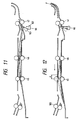
- a step S38 the paired rollers 45 and 46 are rotated in a reverse direction, thus returning the whole remaining stacked sheets in an upstream direction (shown by an arrow in Fig. 12). Then, when the leading edge of an uppermost sheet is shifted by the predetermined distance l from the paired rollers 45 in a downstream direction as shown in Fig. 12 (in a step S39), the paired rollers 45 and 46 are stopped (in a step S310), thus waiting until the fed sheet is copied and is returned to the sheet re-feeding path.
- the paired rollers 45 and 46 are rotated by the predetermined amount (in steps S313, S314 and S315), thus overlapping the returned sheet on the uppermost sheet with shifting the leading edge of the returned sheet by the distance l in the upstream direction with respect to the uppermost sheet.
- the second image forming operation regarding all of the sheets is finished, and all of the sheets are again in the stacked condition with shifting by the predetermined distance l one another, as shown in Fig. 8. Then, the sequence returns to the step S312.
- the third image forming operation can be started by feeding the lowermost sheet in the sheet stack to the photosensitive drum.
- the fourth image forming operation can be performed. In this way, n (in number) image forming operations on the single sheet can be performed with respect to a plurality of sheets successively.
- the paired rollers 45 and 46 are driven by the respective stepping motors each of which is reversible and can be controlled to rotate by a desired rotation angle corresponding to a desired feeding distance for the sheets.
- the sheets on which the image is formed in the second image forming operation are stacked successively on the stacked sheets on which the image is formed in the first image forming operation, with shifting by the predetermined distance one another. Accordingly, the first sheet on which the image is formed in the second image forming operation is overlapped on the uppermost sheet (the last sheet) of the stacked sheets on each of which the first image is formed and which wait for the second image forming operation, with shifting by the distance l one another.
- the number of the firstly stacked sheets is previously stored or memorized, and the feeding operations are repeated by times corresponding to the memorized number.
- the memorized number there will arise a difference between the memorized number and the number of sheets actually fed. That is to say, there is a danger that the sheet on which the second image has already been formed is erroneously detected as the last sheet for the second image forming operation and such sheet is fed for the second image forming operation.
- the sheet stack inclduing the sheets on which the image is formed is overlapped on the sheet stack being fed, with shifting by a distance larger than the predetermined distance l (between the sheets) one another, thus separating two kinds of sheet stacks from each other.
- the leading edge of the uppermost sheet of such sheet stack is previously positioned downstream of the paired rollers 45 with spacing therefrom by a distance l′ larger than the distance l (Figs. 13, 14). Accordingly, the first sheet will be overlapped on the sheet stack with shifting by the distance l′ with respect to the uppermost sheet of the sheet stack.
- the second sheet is overlapped on the first sheet with shifting by the distance l one another, and third, fourth, ... final sheets are similarly overlapped on the previous sheet with shifting by the distance l one another.
- the second sheet stack including the sheets on which the second image is formed is spaced apart from the first sheet stack to be fed for the second image forming operation by the distance l′, the second sheet stack does not come into the feeding condition (i.e., the lowermost sheet of the second sheet stack does not reach the paired rollers 46) immediately after the first sheet stack is emptied. Accordingly, in this condition, if the re-feed rollers 47 are driven, the second sheet stack is not fed because it is held stationary by the stopped rollers 46. In this way, the erroneous feeding of the sheet can be prevented. Further, if it is so designed that the boundary between the first and second sheet stacks can be detected by the sensor 66, the erroneous feeding of the sheet will be further positively prevented.
- the condition that the first sheet stack is emptied can be detected.
- the number of the sensors and/or the position thereof are not limited to the illustrated embodiments.
- the number of pairs of rollers is not limited to two.
- only one pair of rollers may be used in the smaller image forming apparatus, and three or more pairs of rollers may be used in the larger image forming apparatus.
- the present invention was applied to the copying machine, it should be noted that the present invention is not limited to the copying machine, but can be applied to the whole image forming apparatuses which can output the image on the sheet, such as a printer, facsimile, plotter and the like.
Landscapes
- Physics & Mathematics (AREA)
- General Physics & Mathematics (AREA)
- Paper Feeding For Electrophotography (AREA)
- Conveyance By Endless Belt Conveyors (AREA)
- Sheets, Magazines, And Separation Thereof (AREA)
- Separation, Sorting, Adjustment, Or Bending Of Sheets To Be Conveyed (AREA)
- Delivering By Means Of Belts And Rollers (AREA)
Claims (21)
- Blatt-Zuführvorrichtung, die umfaßt:- Blatt-Stapeleinrichtungen zur Stapelung von Blättern nacheinander unter Verschiebung mit einem vorbestimmten Wert eines vom anderen in einer Blatt-Förderrichtung;- Fördereinrichtungen zum Fördern der Blätter eines nach dem anderen von einem Blattstapel, der durch Stapeln der Blätter unter Verschiebung mit einem vorbestimmten Wert eines zum anderen erhalten wurde;- Transporteinrichtungen zum Transport des genannten, durch die erwähnten Blatt-Stapeleinrichtungen gebildeten Blattstapels in normaler und umgekehrter Richtung zwischen den erwähnten Blatt-Stapeleinrichtungen sowie den besagten Fördereinrichtungen; und- Steuereinrichtungen zur Steuerung der genannten Transporteinrichtungen in einer solchen Weise, daß die genannten Transporteinrichtungen den besagten Blattstapel zu den erwähnten Blatt-Stapeleinrichtungen transportieren, wenn die Blätter gestapelt werden, und den besagten Blattstapel zu den erwähnten Fördereinrichtungen transportieren, wenn die Blätter gefördert werden.
- Blatt-Zuführvorrichtung nach Anspruch 1, in welcher die erwähnten Blatt-Stapeleinrichtungen eine Schale enthalten, auf welcher die Blätter gestapelt werden.
- Blatt-Zuführvorrichtung nach Anspruch 1, in welcher die erwähnten Blatt-Stapeleinrichtungen transportierende Drehelemente besitzen, um das Blatt zusammen mit den vorher geförderten Blättern jedesmal zu fördern, wenn das Blatt dorthin gefördert wird.
- Blatt-Zuführvorrichtung nach Anspruch 1, in welcher die besagten Fördereinrichtungen das Blatt fördern, während dieses Blatt zwischen ihnen eingeklemmt wird.
- Blatt-Zuführvorrichtung nach Anspruch 4, in welcher die besagten Fördereinrichtungen ein Paar von fördernden Drehelementen enthalten, um das Blatt zwischen diesen einzuklemmen.
- Blatt-Zuführvorrichtung nach Anspruch 1, in welcher die genannten Transporteinrichtungen das Blatt transportierren, während dieses Blatt zwischen ihnen eingeklemmt wird.
- Blatt-Zuführvorrichtung nach Anspruch 6, in welcher die besagten Fördereinrichtungen ein Paar von zweiten fördernden Drehelementenenthalten, um das Blatt zwischen diesen einzuklemmen.
- Blatt-Zuführvorrichtung nach Anspruch 6, in welcher die erwähnten Steuereinrichtungen die genannten Transporteinrichtungen in einer solchen Weise steuern, daß, wenn das Blatt gefördert wird, die genannten Transporteinrichtungen den besagten Blattstapel zu den erwähnten Fördereinrichtungen transportieren, bis ein Blatt in dem besagten Stapel, das den erwähnten Fördereinrichtungen am nächsten ist, aus einem geklemmten Zustand durch die genannten Transporteinrichtungen freigegeben wird.
- Blatt-Zuführvorrichtung nach Anspruch 8, in welcher die genannten Transporteinrichtungen, wenn das Blatt gefördert wird, die Blätter außer einem, das durch die besagten Fördereinrichtungen zu fördern ist, einklemmen.
- Bilderzeugungsgerät, das umfaßt:- Bilderzeugungseinrichtungen, um eine Abbildung an einem Blatt auszubilden;- Blatt-Stapeleinrichtungen, um aufeinanderfolgend Blätter, an welchen die Abbildung durch die genannten Bilderzeugungseinrichtungen ausgebildet wird, unter Verschiebung mit einem vorbestimmten Wert eines vom anderen in einer Blatt-Förderrichtung zu stapeln;- Fördereinrichtungen zum Fördern der Blätter eines nach dem anderen von einem Blattstapel, der durch Stapeln der Blätter unter Verschiebung mit einem vorbestimmten Wert eines zum anderen erhalten wurde;- Transporteinrichtungen zum Transport des genannten, durch die erwähnten Blatt-Stapeleinrichtungen gebildeten Blattstapels in normaler und umgekehrter Richtung zwischen den erwähnten Blatt-Stapeleinrichtungen sowie den besagten Fördereinrichtungen; und- Steuereinrichtungen zur Steuerung der genannten Transporteinrichtungen in einer solchen Weise, daß die genannten Transporteinrichtungen den erwähnten Blattstapel von den besagten Fördereinrichtungen zu den genannten Blatt-Stapeleinrichtungen zurückführen, um die Blätter, auf denen die Abbildung durch die besagten Bilderzeugungseinrichtungen ausgebildet wird, nachdem sie durch die besagten Fördereinrichtungen gefördert worden sind, zu stapeln, um einen neuen Blattstapel zu erhalten.
- Bilderzeugungsgerät nach Anspruch 10, in welchem die erwähnten Blatt-Stapeleinrichtungen transportierende Drehelemente besitzen, um das Blatt zusammen mit den vorher geförderten Blättern jedesmal zu fördern, wenn das Blatt dorthin gefördert wird.
- Bilderzeugungsgerät nach Anspruch 10, in welchem die besagten Fördereinrichtungen das Blatt fördern, während dieses Blatt zwischen ihnen eingeklemmt wird.
- Bilderzeugungsgerät nach Anspruch 12, in welchem die besagten Fördereinrichtungen ein Paar von fördernden Drehelementen enthalten, um das Blatt zwischen diesen einzuklemmen.
- Bilderzeugungsgerät nach Anspruch 10, in welchem die genannten Transporteinrichtungen das Blatt transportieren, während dieses Blatt zwischen ihnen eingeklemmt wird.
- Bilderzeugungsgerät nach Anspruch 14, in welchem die Steuereinrichtungen die genannten Transporteinrichtungen in einer solchen Weise steuern, daß diese Transporteinrichtungen den besagten Blattstapel zu den erwähnten Fördereinrichtungen transportieren, bis ein Blatt in dem besagten Stapel, das den erwähnten Fördereinrichtungen am nächsten ist, aus einem geklemmten Zustand durch die genannten Transporteinrichtungen freigegeben wird, um die Blätter mittels der erwähnten Fördereinrichtungen zu fördern.
- Bilderzeugungsgerät nach Anspruch 15, in welchem die genannten Transporteinrichtungen, wenn das Blatt gefördert wird, die Blätter außer einem, das durch die besagten Fördereinrichtungen zu fördern ist, einklemmen.
- Bilderzeugungsgerät nach Anspruch 15, in welchem die genannten Transporteinrichtungen und die erwähnten Blatt-Stapeleinrichtungen transportierende Drehelemente besitzen, die drehbar sind, während sie gemeinsam das Blatt zwischen sich einklemmen.
- Blatt-Zuführvorrichtung, die umfaßt:- erste Transporteinrichtungen, um ein Blatt in einer vorbestimmten Richtung zu transportieren;- eine Schale, um die Blätter, die in der besagten ersten Transporteinrichtung transportiert werden, zu stapeln;- Bewegungseinrichtungen, um die auf der genannten Schale gestapelten Blätter zu verschieben, um das von der besagten ersten Transporteinrichtung transportierte Blatt einem vorher auf der genannten Schale gestapelten Blatt unter einer Verschiebung mit einer vorbestimmten Strecke in der erwähnten vorbestimmten Richtung mit Bezug zu dem besagten vorher gestapelten Blatt zu überlagern;- Fördereinrichtungen zum Fördern der Blätter eines nach dem anderen von einem Blattstapel, der durch Stapeln der Blätter unter Verschiebung mit der vorbestimmten Strecke eines vom anderen erhalten wurde; und- zweite Transporteinrichtungen, um den genannten, durch Stapeln der Blätter unter Verschiebung um die vorbestimmte Strecke eines zum anderen erhaltenen Blattstapel zu den erwähnten Fördereinrichtungen zu transportieren und um den genannten Blattstapel von den erwähnten Fördereinrichtungen zu der besagten Schale zu transportieren.
- Blatt-Zuführvorrichtung nach Anspruch 18, in welcher die besagten Bewegungseinrichtungen ein Blatt zusammen mit vorher gestapelten sowie um die vorbestimmte Strecke verschobenen Blättern jedesmal, wenn das Blatt auf der genannten Schale gestapelt wird, bewegen.
- Blatt-Zuführvorrichtung nach Anspruch 18, in welcher die besagten Bewegungseinrichtungen das Blatt in der erwähnten vorbestimmten Richtung um eine erste vorbestimmte Strecke bewegen, bis eine nachlaufende Kante des genannten Blatts durch die besagten ersten Transporteinrichtungen durchläuft, und anschließend das genannte Blatt in einer umgekehrten Richtung um eine zweite vorbestimmte Strecke, die kürzer als die erwähnte erste vorbestimmte Strecke ist, zurückführen.
- Blatt-Zuführvorrichtung nach Anspruch 18, in welcher die erwähnten zweiten Transporteinrichtungen den genannten Blattstapel in eine Position transportieren, in der das von den besagten ersten Transporteinrichtungen transportierte Blatt einem Blatt des genannten Blattstapels, das den besagten ersten Transporteinrichtungen am nächsten ist, unter Verschiebung mit der vorbestimmten Strecke zueinander überlagert werden kann.
Applications Claiming Priority (2)
| Application Number | Priority Date | Filing Date | Title |
|---|---|---|---|
| JP63123682A JPH01294127A (ja) | 1988-05-20 | 1988-05-20 | 画像形成装置 |
| JP123682/88 | 1988-05-20 |
Publications (3)
| Publication Number | Publication Date |
|---|---|
| EP0342704A2 EP0342704A2 (de) | 1989-11-23 |
| EP0342704A3 EP0342704A3 (en) | 1990-11-28 |
| EP0342704B1 true EP0342704B1 (de) | 1993-08-04 |
Family
ID=14866708
Family Applications (1)
| Application Number | Title | Priority Date | Filing Date |
|---|---|---|---|
| EP89109090A Expired - Lifetime EP0342704B1 (de) | 1988-05-20 | 1989-05-19 | Bilderzeugungsgerät |
Country Status (4)
| Country | Link |
|---|---|
| US (1) | US5090674A (de) |
| EP (1) | EP0342704B1 (de) |
| JP (1) | JPH01294127A (de) |
| DE (1) | DE68908006T2 (de) |
Families Citing this family (17)
| Publication number | Priority date | Publication date | Assignee | Title |
|---|---|---|---|---|
| US5093674A (en) * | 1990-08-02 | 1992-03-03 | Hewlett-Packard Company | Method and system for compensating for paper shrinkage and misalignment in electrophotographic color printing |
| BE1008208A4 (nl) * | 1991-03-26 | 1996-02-13 | Gaspar A H Byttebier | Werkwijze en inrichting voor het verhandelen van vellen. |
| WO1993004409A1 (en) * | 1991-08-14 | 1993-03-04 | Indigo N.V. | Duplex printer |
| US5552875A (en) * | 1991-08-14 | 1996-09-03 | Indigo N.V. | Method and apparatus for forming duplex images on a substrate |
| JP3347384B2 (ja) * | 1993-02-08 | 2002-11-20 | キヤノン株式会社 | 画像形成装置 |
| JPH10268594A (ja) * | 1997-03-26 | 1998-10-09 | Canon Inc | 画像形成装置 |
| US6608979B1 (en) | 1998-05-24 | 2003-08-19 | Indigo N.V. | Charger for a photoreceptor |
| US6912952B1 (en) | 1998-05-24 | 2005-07-05 | Hewlett-Packard Indigo B.V. | Duplex printing system |
| US6823786B1 (en) | 1999-11-07 | 2004-11-30 | Hewlett-Packard Indigo B.V. | Tandem printing system with fine paper-position correction |
| US6851672B1 (en) | 2000-04-18 | 2005-02-08 | Hewlett-Packard Indigo B.V. | Sheet transport position and jam monitor |
| US6363234B2 (en) | 2000-11-21 | 2002-03-26 | Indigo N.V. | Printing system |
| US7766327B2 (en) * | 2006-09-27 | 2010-08-03 | Xerox Corporation | Sheet buffering system |
| JP4893610B2 (ja) * | 2007-12-13 | 2012-03-07 | 富士ゼロックス株式会社 | 記録材搬送装置及びこれを用いた画像形成装置 |
| JP5817292B2 (ja) * | 2011-07-26 | 2015-11-18 | グラドコジャパン株式会社 | 用紙処理装置 |
| JP5919677B2 (ja) * | 2011-08-18 | 2016-05-18 | ブラザー工業株式会社 | 画像形成装置 |
| JP5503708B2 (ja) | 2011-10-06 | 2014-05-28 | キヤノン株式会社 | シート処理装置及び画像形成装置 |
| JP6405901B2 (ja) * | 2014-11-04 | 2018-10-17 | コニカミノルタ株式会社 | 画像形成装置 |
Family Cites Families (8)
| Publication number | Priority date | Publication date | Assignee | Title |
|---|---|---|---|---|
| DE2811197C2 (de) * | 1978-03-15 | 1983-04-21 | Maschinenbau Oppenweiler Gmbh, 7155 Oppenweiler | Rundstapelbogenanleger |
| US4172655A (en) * | 1978-06-26 | 1979-10-30 | Xerox Corporation | Shingle sheet stacking for duplex copying |
| DD211771A1 (de) * | 1982-11-25 | 1984-07-25 | Polygraph Leipzig | Anleger zur kontinuierlichen zufuehrung von vereinzelten bogenlagen |
| US4777498A (en) * | 1985-05-14 | 1988-10-11 | Canon Kabushiki Kaisha | Image forming apparatus |
| JPS62293258A (ja) * | 1986-06-12 | 1987-12-19 | Canon Inc | 画像処理装置 |
| DE3783867T2 (de) * | 1986-10-28 | 1993-08-12 | Canon Kk | Adaptiereinrichtung fuer eine entwicklungsvorrichtung sowie bilderzeugungsgeraet und entwicklungsvorrichtung. |
| US4805890A (en) * | 1987-08-06 | 1989-02-21 | Merrill David Martin | Sheet stacking machine |
| DE3852234T2 (de) * | 1987-08-12 | 1995-05-04 | Canon Kk | Apparat zum Fördern von Bogen und Verfahren zum Fördern von Bogen. |
-
1988
- 1988-05-20 JP JP63123682A patent/JPH01294127A/ja active Pending
-
1989
- 1989-05-19 EP EP89109090A patent/EP0342704B1/de not_active Expired - Lifetime
- 1989-05-19 DE DE89109090T patent/DE68908006T2/de not_active Expired - Fee Related
-
1990
- 1990-04-18 US US07/512,538 patent/US5090674A/en not_active Expired - Lifetime
Also Published As
| Publication number | Publication date |
|---|---|
| DE68908006T2 (de) | 1993-12-09 |
| US5090674A (en) | 1992-02-25 |
| EP0342704A3 (en) | 1990-11-28 |
| EP0342704A2 (de) | 1989-11-23 |
| JPH01294127A (ja) | 1989-11-28 |
| DE68908006D1 (de) | 1993-09-09 |
Similar Documents
| Publication | Publication Date | Title |
|---|---|---|
| EP0342704B1 (de) | Bilderzeugungsgerät | |
| EP0427276B1 (de) | Bildaufnahmegerät | |
| US5105229A (en) | Image recording apparatus | |
| JPS60150073A (ja) | 像形成装置 | |
| US5713061A (en) | Image forming apparatus having page designation means | |
| US4937624A (en) | Device for storing developing units | |
| JPH04106561A (ja) | 複写機 | |
| US4610446A (en) | Sheet material transporting apparatus | |
| JP3142313B2 (ja) | 自動原稿搬送装置 | |
| US4963946A (en) | Copying machine capable of discharging paper without forming image thereon | |
| EP0232805B1 (de) | Automatische Bilddichten-Regulierungseinrichtung | |
| US4831414A (en) | Copying apparatus capable of copying a document with binding margin | |
| EP0281096B1 (de) | Verfahren zur Kontrolle der Papierabnahme in einem Bilderzeugungsgerät mit einem Zwischenfach | |
| US5315360A (en) | Copying machine for copying a one-side subject copy on both sides of a copying sheet | |
| US5142323A (en) | Paper feed control method for a copier | |
| JP2977965B2 (ja) | 画像形成装置 | |
| US5510888A (en) | Image forming method and apparatus for forming two images of two originals with control of image forming timing and image reading timing | |
| JPH0733317A (ja) | 画像形成装置 | |
| JP2863921B2 (ja) | 画像形成装置 | |
| JPH028158A (ja) | 画像形成装置 | |
| JP2631126B2 (ja) | 複数現像器収納装置 | |
| JP3036748B2 (ja) | 画像形成装置 | |
| JPH01281467A (ja) | 画像形成装置 | |
| JPH0459575A (ja) | 画像形成装置 | |
| JPH07112899B2 (ja) | 中間トレイを有する画像形成装置の給紙制御方法 |
Legal Events
| Date | Code | Title | Description |
|---|---|---|---|
| PUAI | Public reference made under article 153(3) epc to a published international application that has entered the european phase |
Free format text: ORIGINAL CODE: 0009012 |
|
| AK | Designated contracting states |
Kind code of ref document: A2 Designated state(s): DE FR GB IT |
|
| PUAL | Search report despatched |
Free format text: ORIGINAL CODE: 0009013 |
|
| AK | Designated contracting states |
Kind code of ref document: A3 Designated state(s): DE FR GB IT |
|
| 17P | Request for examination filed |
Effective date: 19901221 |
|
| 17Q | First examination report despatched |
Effective date: 19920604 |
|
| ITF | It: translation for a ep patent filed | ||
| GRAA | (expected) grant |
Free format text: ORIGINAL CODE: 0009210 |
|
| AK | Designated contracting states |
Kind code of ref document: B1 Designated state(s): DE FR GB IT |
|
| REF | Corresponds to: |
Ref document number: 68908006 Country of ref document: DE Date of ref document: 19930909 |
|
| ET | Fr: translation filed | ||
| PLBE | No opposition filed within time limit |
Free format text: ORIGINAL CODE: 0009261 |
|
| STAA | Information on the status of an ep patent application or granted ep patent |
Free format text: STATUS: NO OPPOSITION FILED WITHIN TIME LIMIT |
|
| 26N | No opposition filed | ||
| REG | Reference to a national code |
Ref country code: GB Ref legal event code: IF02 |
|
| PGFP | Annual fee paid to national office [announced via postgrant information from national office to epo] |
Ref country code: DE Payment date: 20070517 Year of fee payment: 19 |
|
| PGFP | Annual fee paid to national office [announced via postgrant information from national office to epo] |
Ref country code: GB Payment date: 20070516 Year of fee payment: 19 |
|
| PGFP | Annual fee paid to national office [announced via postgrant information from national office to epo] |
Ref country code: IT Payment date: 20070525 Year of fee payment: 19 |
|
| PGFP | Annual fee paid to national office [announced via postgrant information from national office to epo] |
Ref country code: FR Payment date: 20070510 Year of fee payment: 19 |
|
| GBPC | Gb: european patent ceased through non-payment of renewal fee |
Effective date: 20080519 |
|
| REG | Reference to a national code |
Ref country code: FR Ref legal event code: ST Effective date: 20090119 |
|
| PG25 | Lapsed in a contracting state [announced via postgrant information from national office to epo] |
Ref country code: FR Free format text: LAPSE BECAUSE OF NON-PAYMENT OF DUE FEES Effective date: 20080602 Ref country code: DE Free format text: LAPSE BECAUSE OF NON-PAYMENT OF DUE FEES Effective date: 20081202 |
|
| PG25 | Lapsed in a contracting state [announced via postgrant information from national office to epo] |
Ref country code: GB Free format text: LAPSE BECAUSE OF NON-PAYMENT OF DUE FEES Effective date: 20080519 |
|
| PG25 | Lapsed in a contracting state [announced via postgrant information from national office to epo] |
Ref country code: IT Free format text: LAPSE BECAUSE OF NON-PAYMENT OF DUE FEES Effective date: 20080519 |