EP0342514A2 - Gerät zum Fixieren eines Bogens zur Korrektur von Zahn-Fehlstellungen - Google Patents
Gerät zum Fixieren eines Bogens zur Korrektur von Zahn-Fehlstellungen Download PDFInfo
- Publication number
- EP0342514A2 EP0342514A2 EP89108444A EP89108444A EP0342514A2 EP 0342514 A2 EP0342514 A2 EP 0342514A2 EP 89108444 A EP89108444 A EP 89108444A EP 89108444 A EP89108444 A EP 89108444A EP 0342514 A2 EP0342514 A2 EP 0342514A2
- Authority
- EP
- European Patent Office
- Prior art keywords
- wire
- ligature wire
- tube
- clamping
- hand
- Prior art date
- Legal status (The legal status is an assumption and is not a legal conclusion. Google has not performed a legal analysis and makes no representation as to the accuracy of the status listed.)
- Granted
Links
Images
Classifications
-
- A—HUMAN NECESSITIES
- A61—MEDICAL OR VETERINARY SCIENCE; HYGIENE
- A61C—DENTISTRY; APPARATUS OR METHODS FOR ORAL OR DENTAL HYGIENE
- A61C7/00—Orthodontics, i.e. obtaining or maintaining the desired position of teeth, e.g. by straightening, evening, regulating, separating, or by correcting malocclusions
- A61C7/02—Tools for manipulating or working with an orthodontic appliance
- A61C7/026—Tools for manipulating or working with an orthodontic appliance for twisting orthodontic ligature wires
-
- A—HUMAN NECESSITIES
- A61—MEDICAL OR VETERINARY SCIENCE; HYGIENE
- A61C—DENTISTRY; APPARATUS OR METHODS FOR ORAL OR DENTAL HYGIENE
- A61C7/00—Orthodontics, i.e. obtaining or maintaining the desired position of teeth, e.g. by straightening, evening, regulating, separating, or by correcting malocclusions
- A61C7/02—Tools for manipulating or working with an orthodontic appliance
Definitions
- the invention relates to a device and a method for fixing an arch formed from a wire for correcting tooth misalignments of the human dentition, the bottom in holder plates (brackets), each of which a holder plate is attached to the labial or lingual surface of the teeth , inserted and fixed by a ligature wire to the holder plates using a tool, and a ligature wire.
- a wire arch for correcting tooth misalignment of a bit of a so-called band-arch apparatus
- holder plates so-called brackets
- a lock is recessed into which the wire arch can be inserted. So that the force of the arch can be transferred to the teeth, it is necessary to fix this arch to the holder plates.
- This fixation can be achieved in various ways, for example by rubber rings or fine wires, the latter fixation being referred to as a ligature.
- fine wires with a thickness of a few tenths of a millimeter, for example 0.2-0.3 mm, are used, which are placed around the holder plates and the ends of which are twisted to tension the wire.
- the ligature wire lies here over the arch and extends below two wings arranged on the holder plates so that it cannot be stripped off.
- the fixation is usually done with a needle holder in which a ligature wire is clamped.
- a twister is known (JP utility model 1 373 903), with which the application and tensioning of the ligature wires on the holder plates is simplified.
- the twister is designed as a rod-shaped device, at one end of which two jaws are mounted, one of which is displaceable.
- a pin is exposed, over which a ligature wire in the form of a closed loop is placed, whereupon the jaw pushed back is pushed forward again.
- the loop can be placed over the holder plate and the twister rotated by hand until the ligature wire is snug against the holder plate. Then the jaw can be pushed back and the twisted end of the loop can be removed from the pin.
- a clamping head for clamping the ends of a ligature wire shaped as a loop is arranged at the end of a tool designed as a rod, which is rotated several times by a rotating mechanism housed inside the rod for the purpose of twisting and tensioning the one around the holder plate Ligature wire can be issued.
- the invention also includes a method using the device according to the invention, in which a ligature wire is formed in the form of a loop and is clamped with its two ends in the collet of the device, the ends of which are twisted after being applied to the holder plates by actuating the rotating mechanism of the device will.
- the invention further comprises a ligature wire in the form of a wire loop for carrying out the method according to the invention, which is provided with two legs connected by a web, the legs in the vicinity of the web having a portion with a smaller spacing than at the adjoining portion, which the holder plate is intended to be placed, with the end parts of the inns lying next to each other with a smaller distance.
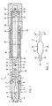
- the device 1 shown in FIG. 1 and the ligature wire 2 shown in FIG. 2 are shown on an enlarged scale.
- the device 1, which is referred to below as the twister 1 has a rod shape and has an internal torsion bar 3 on which a clamping head 4 is mounted.
- the clamping head 4 is composed of a sleeve 5 and two clamping jaws 6.
- the jaws 6 are mounted in the torsion bar 3 at the end.
- a slot 7 is provided at the end of the torsion bar 3, in which the plate-shaped clamping jaws 6 are pivotally mounted.
- the jaws 6 are held at their inner ends by a threaded bolt 8, which is screwed into the sleeve 5 and protrudes radially inwards into a recess 9 in the jaws 6.
- the recess 7 in the torsion bar 3 does not extend to the end 10 of the torsion bar 3; the torsion bar 3 is conical at this point and has an opening 11 through which a pin 12 passes.
- Another pin 13 mounted in the torsion bar 3 passes through the slot 7 and separates the two clamping jaws 6.
- a compression spring 15 acts with one end, while its other end is in one Torsion bar 3 supported bearing pin 16 which traverses the longitudinal bore 17 of the torsion bar 3.
- the clamping jaws 6 are pressed against the inner cone of the conical end 10, whereby they exert a clamping effect.
- the ends of the ligature wire shown in Fig. 2 can be placed and clamped between the jaws.
- the sleeve 5 is pushed back, as a result of which the jaws move along the further pin 13 and are spread according to the design of their inner contour, so that the ligature wire 2 can be inserted.
- the torsion bar 3 is surrounded by a sleeve-shaped hand tube 20, the inner bore 21 of which has a larger diameter than the outer diameter of the torsion bar 3, so that an annular space 21 'is formed between the inner wall of the hand tube 20 and the outer diameter of the torsion bar 3.
- the hand tube 20 is connected at its end facing away from the clamping head 4 to an end tube 22 which is closed off from the outside and whose inner diameter 23 corresponds approximately to the diameter of the inner bore 21 of the hand tube 20.
- the longitudinal bore 17 of the torsion bar 3 is traversed by a tension spring 24, of which the one end 24 'in a bore 17 of the torsion bar 3 passing through the holding rod 25 and the other end 24' in a bottom of the tail pipe 22 mounted further retaining pin 27 is mounted .
- threads 28 with a semicircular cross section are incorporated, while corresponding threads 29 with an approximately semicircular cross section are provided on the inner wall of the hand pipe 20.
- the threads 28 and 29 can be one, two or more threads.
- the pitch of the threads 28, 29 can also be varied, e.g. B. be formed with increasing incline.
- a ball cage 30 with balls 31 is mounted, which establishes the connection between the threads 28, 29 and causes rotation of the torsion bar 3 when the hand tube 20 or the end tube 22 is moved.
- balls 31 In Fig. 1 only four balls 31 are shown, but in reality a number of further balls 31 are arranged over the entire ball cage.
- a stop 32 for example a snap ring 32, is fastened to the end pipe-side end of the torsion bar 3 and limits the stroke between the rotary pipe 3 and the hand pipe 20 or the end pipe 22.
- a disc 33 is inserted, which dampens the impact of the rotary pipe 3.
- the sleeve 5 After pulling back the sleeve 5 and inserting the ligature wire 2 between the jaws 6, the sleeve 5 is released again so that it slides back into the position shown in FIG. 1.
- the ligature wire 2 is placed over one of the brackets after laying the arch for the correction of the teeth, whereupon the hand tube 20 or the end tube 22 is withdrawn. This causes a rotary movement of the clamping head 4, by means of which the ends of the ligature wire 2 are twisted and at the same time the ligature wire 2 is snugly placed on the brackets and the arch is thereby fixed.
- the ligature wire 2 intended for use with the device 1 is designed as a two-leg loop, the legs 34, 35 of which are connected to one another by a web 36.
- the leg portions 34 ', 35' have a smaller distance than in the adjoining central portion 34 ⁇ and 35 ⁇ .
- the end games 34 ′′′, 35 ′′′ of the legs 34, 35 run approximately parallel to each other and have a smaller distance than the other leg parts. It is essential that there is a distance between the end parts of the legs 34, 35 which is somewhat larger than the diameter of the pin 12 which is arranged in the conical end 10 of the torsion bar 3.
- the ligature wire 2 Since the ligature wire 2 is required in large numbers, it must be provided appropriately, which e.g. can be achieved with a dispenser that dispenses one ligature wire at a time.
Landscapes
- Health & Medical Sciences (AREA)
- Oral & Maxillofacial Surgery (AREA)
- Dentistry (AREA)
- Epidemiology (AREA)
- Life Sciences & Earth Sciences (AREA)
- Animal Behavior & Ethology (AREA)
- General Health & Medical Sciences (AREA)
- Public Health (AREA)
- Veterinary Medicine (AREA)
- Dental Tools And Instruments Or Auxiliary Dental Instruments (AREA)
Abstract
Description
- Die Erfindung betrifft ein Gerät und ein Verfahren zum Fixieren eines aus einem Draht geformten Bogens zur Korrektur von Zahn-Fehlstellungen des menschlichen Gebisses, wobei der Boden in Halterplatten (Brackets), von denen je eine Halterplatte auf der Labial- oder Lingualfläche der Zähne befestigt ist, eingelegt und durch einen Ligaturendraht unter Benützung eines Werkzeuges an den Halterplatten fixiert ist, sowie einen Ligaturendraht.
- In der Kieferorthopädie ist die Verwendung eines Drahtbogens zur Korrektur von Zahn-Fehlstellungen eines Gebisses einer sog. Band-Bogenapparatur ein bekanntes Verfahren. Hierzu werden an der Labial- bzw. Lingualfläche der Zähne Halterplatten, sog. Brackets, befestigt, in denen ein Schloss ausgespart ist, in welches der Drahtbogen eingelegt werden kann. Damit die Kraft des Bogens auf die Zähne übertragen werden kann, ist es erforderlich, diesen Bogen an den Halterplatten zu fixieren. Diese Fixierung kann auf verschiedene Art und Weise erreicht werden, beispielsweise durch Gummiringe oder feine Drähte, welch letztere Fixierung als Ligatur bezeichnet wird.
- Das Anlegen und Fixieren eines solchen Drahtbogens ist eine verhältnismässig aufwendige Arbeit, insbesondere dann, wenn eine Korrektur der Zähne sowohl des Oberkiefers als auch des Unterkiefers vorgesehen werden muss.
- Für die Ligaturen bedient man sich feiner Drähte mit einer Stärke von einigen Zehntel Millimeter, beispielsweise 0,2-0,3 mm, die um die Halterplatten gelegt und deren Enden zum Spannen des Drahtes verdrillt werden. Der Ligaturendraht legt sich hierbei über den Bogen und erstreckt sich unterhalb zweier an den Halterplatten angeordneten Flügel, damit er nicht abgestreift werden kann.
- Die Fixierung geschieht in der Regel mit einem Nadelhalter, in den ein Ligaturdraht eingespannt wird.
- Es ist ein Twister bekannt (JP-Gebrauchsmuster 1 373 903), mit welchem das Anlegen und Spannen der Ligaturendrähte auf den Halterplatten vereinfacht wird. Der Twister ist als stabförmiges Gerät ausgebildet, an dessen einem Ende zwei Backen gelagert sind, von denen die eine Backe verschiebbar ist. Beim Zurückschieben dieser Backe wird ein Stift freigelegt, über welchen ein Ligaturendraht in Form einer geschlossenen Schlaufe gelegt wird, worauf die zurückgeschobene Backe wieder vorgeschoben wird. Nun kann die Schlaufe über die Halterplatte gelegt und der Twister von Hand solange gedreht werden, bis der Ligaturendraht satt an der Halterplatte anliegt. Dann kann die Backe wieder zurückgeschoben und das verdrillte Ende der Schlaufe aus dem Stift entfernt werden.
- Bei diesem bekannten Gerät ist es erforderlich, die Verdrillung durch Drehen des Gerätes von Hand zu erreichen. Erfahrungsgemäss werden für eine Ligatur etwa fünfzehn Umdrehungen benötigt, wobei diese Zahl von der Grösse der Halterplatte und von der Art der Vorverformung des Ligaturendrahtes abhängig ist. Diese verhältnismässig grosse Umdrehungszahl stellt einen entsprechend grossen zeitlichen und physischen Aufwand dar.
- Hier setzt die Erfindung ein, der die Aufgabe zugrunde liegt, ein Gerät der eingangs beschriebenen Art so weiter auszugestalten, dass die Ligaturen ohne Assistenz und mit geringem zeitlichem und physischem Aufwand ausgeführt werden können.
- Diese Aufgabe wird gemäss der Erfindung dadurch gelöst, dass an dem Ende eines als Stab ausgebildeten Werkzeuges ein Spannkopf zum Klemmen der Enden eines als Schlaufe geformten Ligaturendrahtes angeordnet ist, dem durch einen im Stabinnern untergebrachten Drehmechanismus mehrere Umdrehungen zwecks Verdrillen und Spannen des um die Halterplatte gelegten Ligaturendrahtes erteilbar sind.
- Die Erfindung umfasst auch ein Verfahren unter Verwendung des erfindungsgemässen Gerätes, bei welchem ein Ligaturendraht in Form einer Schlaufe gebildet und mit ihren beiden Enden in der Spannzange des Gerätes festgeklemmt wird, wobei deren Enden nach dem Anlegen an die Halterplatten durch Betätigen des Drehmechanismus des Gerätes verdrillt werden.
- Die Erfindung umfasst weiter einen Ligaturendraht in Form einer Drahtschlaufe zur Durchführung des erfindungsgemässen Verfahrens, der mit zwei durch einen Steg verbundene Schenkel versehen ist, wobei in der Nähe des Steges die Schenkel eine Partie mit einem kleineren Abstand aufweisen als an der anschliessenden Partie, die über die Halterplatte zu legen bestimmt ist, wobei die Endpartien der Schenke mit kleinerem Abstand nebeneindander liegen.
- Die Erfindung ist in der Zeichnung in einem Ausführungsbeispiel dargestellt und nachfolgend beschrieben.
- Es zeigen:
- Fig. 1 Einen Längsschnitt eines als Stab ausgebildeten Gerätes zum Anbringen von Ligaturendrähten an Brackets zum Fixieren eines Bogens zur Korrektur von Zähnen und
- Fig. 2 Eine Seitenansicht eines Ligaturendrahtes, der mit dem Gerät nach Fig. 1 zum Fixieren des Bogens verwendet werden kann.
- Das in Fig. 1 dargestellte Gerät 1 und der in Figur 2 dargestellte Ligaturendraht 2 sind in vergrössertem Massstab dargestellt. Das Gerät 1, das nachfolgend als Twister 1 bezeichnet wird, weist Stabform auf und weist einen innenliegenden Drehstab 3 auf, an welchem ein Spannkopf 4 gelagert ist.
- Der Spannkopf 4 setzt sich aus einer Hülse 5 und zwei Spannbacken 6 zusammen. Die Spannbacken 6 sind im Drehstab 3 an dessen Ende gelagert. Hierzu ist am Ende des Drehstabes 3 ein Schlitz 7 vorgesehen, in welchem die plättchenförmigen Spannbacken 6 schwenkbar gelagert sind. Die Spannbacken 6 sind an ihrem inneren Ende durch je einen Gewindebolzen 8 gehalten, welcher in die Hülse 5 eingeschraubt ist und radial einwärts in eine Vertiefung 9 der Spannbacken 6 ragt.
- Der in dem Drehstab 3 ausgesparte Schlitz 7 erstreckt sich nicht bis zum Ende 10 des Drehstabes 3; der Drehstab 3 ist an dieser Stelle konisch ausgebildet und weist eine Oeffnung 11 auf, die von einem Stift 12 durchquert wird. Ein weiterer im Drehstab 3 gelagerter Stift 13 durchquert den Schlitz 7 und trennt die beiden Spannbacken 6.
- Auf das innenseitige Ende der Spannbacken 6 wirkt eine Druckfeder 15 mit ihrem einen Ende, während ihr anderes Ende sich an einen im Drehstab 3 gelagerten Lagerstift 16 abstützt, der die Längsbohrung 17 des Drehstabes 3 durchquert. Durch die Druckfeder 15 werden die Spannbacken 6 gegen den Innenkonus des konischen Endes 10 gedrückt, wobei sie eine Klemmwirkung ausüben. Zwischen den Backen können die Enden des in Fig. 2 dargestellten Ligaturdrahtes gelegt und geklemmt werden. Zum Einlegen des Ligaturendrahtes zwischen die Spannbacken 6 wird die Hülse 5 zurückgeschoben, wodurch die Spannbacken sich längs des weiteren Stiftes 13 bewegen und entsprechend der Ausbildung ihrer Innenkontur gespreizt werden, sodass der Ligaturendraht 2 eingelegt werden kann.
- Der Drehstab 3 ist von einem hülsenförmigen Handrohr 20 umgeben, dessen Innenbohrung 21 einen grösseren Durchmesser aufweist als der Aussendurchmesser des Drehstabes 3, sodass ein Ringraum 21′ zwischen der Innenwand des Handrohrs 20 und dem Aussendurchmesser des Drehstabes 3 entsteht.
- Das Handrohr 20 ist an seinem, dem Spannkopf 4 abgewandten Ende mit einem nach aussen abgeschlossenen Endrohr 22 verbunden, dessen Innendurchmesser 23 etwa dem Durchmesser der Innenbohrung 21 des Handrohrs 20 entspricht.
- Die Längsbohrung 17 des Drehstabes 3 wird von einer Zugfeder 24 durchquert, von welcher das eine Ende 24′ in einem die Bohrung 17 des Drehstabes 3 durchquerenden Haltestab 25 und das andere Ende 24˝ in einem dem Boden des Endrohres 22 gelagerten weiteren Haltestift 27 gelagert ist. Am endrohrseitigen Ende des Drehstabes 3 sind Gewindegänge 28 mit halbkreisförmigem Querschnitt eingearbeitet, während auf der Innenwand des Handrohrs 20 entsprechende Gewindegänge 29 mit annähernd halbkreisförmigem Querschnitt vorgesehen sind. Die Gewindegänge 28 und 29 können ein-, zwei- oder mehrgängig ausgebildet sein. Auch kann die Steigung der Gewindegänge 28, 29 veränderlich, z. B. mit zunehmender Steigung ausgebildet sein.
- Zwischen den Gewindegängen 28, 29 ist ein Kugelkäfig 30 mit Kugeln 31 gelagert, der die Verbindung zwischen den Gewindegängen 28, 29 herstellt und beim Verschieben des Handrohrs 20 oder des Endrohrs 22 eine Drehung des Drehstabes 3 bewirkt. In Fig. 1 sind nur vier Kugeln 31 dargestellt, jedoch sind in Wirklichkeit über dem ganzen Kugelkäfig eine Anzahl weiterer Kugeln 31 angeordnet.
- Am endrohrseitigen Ende des Drehstabes 3 ist ein Anschlag 32, beispielsweise ein Sprengring 32 befestigt, der den Hub zwischen dem Drehrohr 3 und dem Handrohr 20 bzw. dem Endrohr 22 begrenzt. Im Grund des Endrohrs 22 ist eine Scheibe 33 eingelegt, die den Auftreffschlag des Drehrohres 3 dämpft.
- Das Fixieren des Bogens an die Brackets mit Hilfe des beschriebenen Gerätes gemäss Fig. 2 verläuft wie folgt:
- Nach dem Zurückziehen der Hülse 5 und dem Einlegen des Ligaturendrahtes 2 zwischen die Backen 6 wird die Hülse 5 wieder freigegeben, sodass sie in die in Fig. 1 dargestellte Lage zurückgleitet. Nun wird mit Hilfe des Gerätes 1 der Ligaturendraht 2 nach Verlegen des Bogens für die Korrektur der Zähne über einen der Brackets gelegt, worauf das Handrohr 20 oder das Endrohr 22 zurückgezogen wird. Dadurch wird eine Drehbewegung des Spannkopfes 4 bewirkt, durch welche die Enden des Ligaturendrahtes 2 verdrillt werden und gleichzeitig der Ligaturendraht 2 satt an die Brackets gelegt und dadurch der Bogen fixiert wird.
- Der für die Verwendung mit dem Gerät 1 vorgesehene Ligaturendraht 2 ist, wie aus Fig. 2 erkennbar ist, als zweischenkliche Schlaufe ausgebildet, deren Schenkel 34, 35 durch einen Steg 36 miteinander verbunden sind. Im Bereich des Steges 36 weisen die Schenkelpartien 34′, 35′ einen kleineren Abstand auf als in der daran anschliessenden Mittelpartie 34˝ und 35˝. Die Endpartien 34‴, 35‴ der Schenkel 34, 35 verlaufen etwa parallel zueiander und weisen einen kleineren Abstand auf als die andern Schenkelpartien. Wesentlich ist, dass zwischen den Endpartien der Schenkel 34, 35 ein Abstand besteht, der etwas grösser als der Durchmesser des Stiftes 12 ist, der im konischen Ende 10 des Drehstabes 3 angeordnet ist.
- Da der Ligaturendraht 2 in grossen Stückzahlen benötigt wird, muss er zweckmässig bereitgestellt werden, was z.B. mit einem Dispenser, der jeweils einen Ligaturendraht abgibt, erreicht werden kann.
Claims (10)
Applications Claiming Priority (2)
| Application Number | Priority Date | Filing Date | Title |
|---|---|---|---|
| CH1894/88A CH677185A5 (de) | 1988-05-19 | 1988-05-19 | |
| CH1894/88 | 1988-05-19 |
Publications (3)
| Publication Number | Publication Date |
|---|---|
| EP0342514A2 true EP0342514A2 (de) | 1989-11-23 |
| EP0342514A3 EP0342514A3 (en) | 1990-08-29 |
| EP0342514B1 EP0342514B1 (de) | 1994-01-19 |
Family
ID=4221086
Family Applications (1)
| Application Number | Title | Priority Date | Filing Date |
|---|---|---|---|
| EP89108444A Expired - Lifetime EP0342514B1 (de) | 1988-05-19 | 1989-05-10 | Gerät zum Fixieren eines Bogens zur Korrektur von Zahn-Fehlstellungen |
Country Status (5)
| Country | Link |
|---|---|
| US (1) | US5125830A (de) |
| EP (1) | EP0342514B1 (de) |
| JP (1) | JPH0219143A (de) |
| CH (1) | CH677185A5 (de) |
| DE (1) | DE58906734D1 (de) |
Cited By (2)
| Publication number | Priority date | Publication date | Assignee | Title |
|---|---|---|---|---|
| FR2749153A1 (fr) * | 1996-06-04 | 1997-12-05 | Bordet Pierre | Dispositif pour la realisation de ligatures, notamment en orthodontie |
| KR20190108696A (ko) * | 2018-03-15 | 2019-09-25 | 최연범 | 치과용 와이어 결찰 장치 |
Families Citing this family (4)
| Publication number | Priority date | Publication date | Assignee | Title |
|---|---|---|---|---|
| KR0164257B1 (ko) * | 1995-10-23 | 1999-01-15 | 김중한 | 차이 교정용 결찰철사의 자동 결찰장치 |
| JPH10258069A (ja) * | 1997-01-16 | 1998-09-29 | Yoneo Sugano | リガチャワイヤ用ツイスター |
| US20090017420A1 (en) * | 2006-10-04 | 2009-01-15 | Saadallah Jabri | Gingival Cord Applicator for Dental Crown Preparation |
| JP2015136567A (ja) * | 2014-01-24 | 2015-07-30 | 佩祺 李 | 歯科矯正用自動結紮処理システム |
Family Cites Families (8)
| Publication number | Priority date | Publication date | Assignee | Title |
|---|---|---|---|---|
| GB266596A (en) * | 1926-07-15 | 1927-03-03 | Gustave Werner Mattson | An improved tool for cutting and twisting wire or the like |
| US2416002A (en) * | 1943-12-20 | 1947-02-18 | John J Greer | Wire twisting hand tool |
| US3211188A (en) * | 1962-06-08 | 1965-10-12 | Wallshein Melvin | Tie wire tools for orthodontists and for general industrial use |
| JPS4810872B1 (de) * | 1968-11-14 | 1973-04-07 | ||
| YU263477A (en) * | 1977-11-03 | 1982-05-31 | Zvonko Marusic | Rotary instument for manufacturing wire ligatures |
| DE2750258C3 (de) * | 1977-11-10 | 1980-07-17 | Theo 7715 Braeunlingen Fuchs | Friktionsmeßgerät für Hülsenkronen |
| JPS5532567A (en) * | 1978-08-31 | 1980-03-07 | Matsushita Electric Works Ltd | Apron of bath |
| FR2481595A1 (fr) * | 1980-04-30 | 1981-11-06 | Tramier Jean Claude | Pince pour ligaturer des appareils d'orthopedie dentaire |
-
1988
- 1988-05-19 CH CH1894/88A patent/CH677185A5/de not_active IP Right Cessation
-
1989
- 1989-05-10 EP EP89108444A patent/EP0342514B1/de not_active Expired - Lifetime
- 1989-05-10 DE DE89108444T patent/DE58906734D1/de not_active Expired - Fee Related
- 1989-05-19 JP JP1127734A patent/JPH0219143A/ja active Pending
-
1990
- 1990-11-21 US US07/617,404 patent/US5125830A/en not_active Expired - Fee Related
Cited By (2)
| Publication number | Priority date | Publication date | Assignee | Title |
|---|---|---|---|---|
| FR2749153A1 (fr) * | 1996-06-04 | 1997-12-05 | Bordet Pierre | Dispositif pour la realisation de ligatures, notamment en orthodontie |
| KR20190108696A (ko) * | 2018-03-15 | 2019-09-25 | 최연범 | 치과용 와이어 결찰 장치 |
Also Published As
| Publication number | Publication date |
|---|---|
| JPH0219143A (ja) | 1990-01-23 |
| EP0342514A3 (en) | 1990-08-29 |
| US5125830A (en) | 1992-06-30 |
| DE58906734D1 (de) | 1994-03-03 |
| CH677185A5 (de) | 1991-04-30 |
| EP0342514B1 (de) | 1994-01-19 |
Similar Documents
| Publication | Publication Date | Title |
|---|---|---|
| EP0315215B1 (de) | Vorrichtung zum externen Festlegen von Knochenfragmenten | |
| DE3212828C2 (de) | Chirurgische Klammer und Vorrichtung zum Entfernen von chirurgischen Klammern | |
| DE60201120T2 (de) | Vorrichtung zur Auffindung der Position von Schraubenlöchern zur Fixierung eines Markraumnagels | |
| DE2112138B1 (de) | Huelsenfoermiges Stuetzelement fuer Roehrenknochenfrakturen | |
| DE3526684C1 (de) | Spannvorrichtung zum Einspannen von insbesondere Zahnwerkzeugen | |
| EP0260671B1 (de) | Schläger für Ballspiele, insbesondere Tennisspiele, sowie Bespannvorrichtung hierzu | |
| WO1993009835A1 (de) | Sonde für medizinische eingriffe in körperhöhlen | |
| EP0440682B1 (de) | Verfahren zur bespannung von schlägern für ballspiele sowie vorrichtung zur durchführung des verfahrens | |
| EP1360941B1 (de) | Zahnspange | |
| DE102008004922B4 (de) | Vorrichtung zur Erzeugung eines Hohlraums in Knochengewebe | |
| DE516596T1 (de) | Zahnradwaelzfraesmaschine mit spindelosem system zur unterstuetzung des waelzfraesers. | |
| EP0342514A2 (de) | Gerät zum Fixieren eines Bogens zur Korrektur von Zahn-Fehlstellungen | |
| DE10310004B3 (de) | Chirurgisches Instrument | |
| DE69322856T2 (de) | Matrixspanner sowie integrierbare spannvorrichtung für odontologische anwendung | |
| DE2605460A1 (de) | Vorrichtung zum automatischen befestigen von klammerboegen oder -stuetzen in der kieferorthopaedie | |
| DE102012220602A1 (de) | Chirurgische Fadenspannvorrichtung | |
| DE202016107414U1 (de) | Anschlaghülse | |
| DE19525755C1 (de) | Vorrichtung zum Verbinden von wenigstens zwei axial aneinanderfügbaren Handstückteilen | |
| DE3935969C1 (en) | Fitting plugs in lobes of ears - involves single actuator connected to plug insertion equipment by Bowden cables | |
| DE4334487C1 (de) | Buccale Vorrichtung zur Regulierung von Zähnen | |
| DE2404319A1 (de) | Orthopaedisches geraet zum oeffnen der mittigen sutur des palatums | |
| DE2237801C3 (de) | Impfgerät | |
| DE2935998A1 (de) | Zahnmedizinisches instrument | |
| DE3910235A1 (de) | Einrichtung zum orientierungsrichtigen schleifen von zahnflaechen | |
| DE2337734C3 (de) | Halterung für das Verdrahtungswerkzeug von Verdrahtungsmaschinen, insbesondere nach dem Wire-Wap-Verfahren |
Legal Events
| Date | Code | Title | Description |
|---|---|---|---|
| PUAI | Public reference made under article 153(3) epc to a published international application that has entered the european phase |
Free format text: ORIGINAL CODE: 0009012 |
|
| AK | Designated contracting states |
Kind code of ref document: A2 Designated state(s): DE FR GB IT |
|
| PUAL | Search report despatched |
Free format text: ORIGINAL CODE: 0009013 |
|
| AK | Designated contracting states |
Kind code of ref document: A3 Designated state(s): DE FR GB IT |
|
| RHK1 | Main classification (correction) |
Ipc: A61C 7/02 |
|
| 17P | Request for examination filed |
Effective date: 19910202 |
|
| 17Q | First examination report despatched |
Effective date: 19920619 |
|
| GRAA | (expected) grant |
Free format text: ORIGINAL CODE: 0009210 |
|
| ITF | It: translation for a ep patent filed | ||
| AK | Designated contracting states |
Kind code of ref document: B1 Designated state(s): DE FR GB IT |
|
| REF | Corresponds to: |
Ref document number: 58906734 Country of ref document: DE Date of ref document: 19940303 |
|
| ET | Fr: translation filed | ||
| GBT | Gb: translation of ep patent filed (gb section 77(6)(a)/1977) |
Effective date: 19940408 |
|
| PLBE | No opposition filed within time limit |
Free format text: ORIGINAL CODE: 0009261 |
|
| STAA | Information on the status of an ep patent application or granted ep patent |
Free format text: STATUS: NO OPPOSITION FILED WITHIN TIME LIMIT |
|
| 26N | No opposition filed | ||
| PGFP | Annual fee paid to national office [announced via postgrant information from national office to epo] |
Ref country code: GB Payment date: 19980522 Year of fee payment: 10 |
|
| PGFP | Annual fee paid to national office [announced via postgrant information from national office to epo] |
Ref country code: FR Payment date: 19980527 Year of fee payment: 10 |
|
| PGFP | Annual fee paid to national office [announced via postgrant information from national office to epo] |
Ref country code: DE Payment date: 19980529 Year of fee payment: 10 |
|
| PG25 | Lapsed in a contracting state [announced via postgrant information from national office to epo] |
Ref country code: GB Free format text: LAPSE BECAUSE OF NON-PAYMENT OF DUE FEES Effective date: 19990510 |
|
| GBPC | Gb: european patent ceased through non-payment of renewal fee |
Effective date: 19990510 |
|
| PG25 | Lapsed in a contracting state [announced via postgrant information from national office to epo] |
Ref country code: FR Free format text: LAPSE BECAUSE OF NON-PAYMENT OF DUE FEES Effective date: 20000131 |
|
| PG25 | Lapsed in a contracting state [announced via postgrant information from national office to epo] |
Ref country code: DE Free format text: LAPSE BECAUSE OF NON-PAYMENT OF DUE FEES Effective date: 20000301 |
|
| REG | Reference to a national code |
Ref country code: FR Ref legal event code: ST |
|
| PG25 | Lapsed in a contracting state [announced via postgrant information from national office to epo] |
Ref country code: IT Free format text: LAPSE BECAUSE OF NON-PAYMENT OF DUE FEES;WARNING: LAPSES OF ITALIAN PATENTS WITH EFFECTIVE DATE BEFORE 2007 MAY HAVE OCCURRED AT ANY TIME BEFORE 2007. THE CORRECT EFFECTIVE DATE MAY BE DIFFERENT FROM THE ONE RECORDED. Effective date: 20050510 |