EP0342147B1 - Construction avec chambres admettant un fluide - Google Patents
Construction avec chambres admettant un fluide Download PDFInfo
- Publication number
- EP0342147B1 EP0342147B1 EP89710040A EP89710040A EP0342147B1 EP 0342147 B1 EP0342147 B1 EP 0342147B1 EP 89710040 A EP89710040 A EP 89710040A EP 89710040 A EP89710040 A EP 89710040A EP 0342147 B1 EP0342147 B1 EP 0342147B1
- Authority
- EP
- European Patent Office
- Prior art keywords
- building structure
- structure according
- binders
- chamber
- profile
- Prior art date
- Legal status (The legal status is an assumption and is not a legal conclusion. Google has not performed a legal analysis and makes no representation as to the accuracy of the status listed.)
- Expired - Lifetime
Links
Images


Classifications
-
- E—FIXED CONSTRUCTIONS
- E04—BUILDING
- E04H—BUILDINGS OR LIKE STRUCTURES FOR PARTICULAR PURPOSES; SWIMMING OR SPLASH BATHS OR POOLS; MASTS; FENCING; TENTS OR CANOPIES, IN GENERAL
- E04H15/00—Tents or canopies, in general
- E04H15/20—Tents or canopies, in general inflatable, e.g. shaped, strengthened or supported by fluid pressure
-
- E—FIXED CONSTRUCTIONS
- E04—BUILDING
- E04B—GENERAL BUILDING CONSTRUCTIONS; WALLS, e.g. PARTITIONS; ROOFS; FLOORS; CEILINGS; INSULATION OR OTHER PROTECTION OF BUILDINGS
- E04B1/00—Constructions in general; Structures which are not restricted either to walls, e.g. partitions, or floors or ceilings or roofs
- E04B1/32—Arched structures; Vaulted structures; Folded structures
- E04B1/3211—Structures with a vertical rotation axis or the like, e.g. semi-spherical structures
-
- E—FIXED CONSTRUCTIONS
- E04—BUILDING
- E04H—BUILDINGS OR LIKE STRUCTURES FOR PARTICULAR PURPOSES; SWIMMING OR SPLASH BATHS OR POOLS; MASTS; FENCING; TENTS OR CANOPIES, IN GENERAL
- E04H15/00—Tents or canopies, in general
- E04H15/32—Parts, components, construction details, accessories, interior equipment, specially adapted for tents, e.g. guy-line equipment, skirts, thresholds
- E04H15/64—Tent or canopy cover fastenings
- E04H15/642—Tent or canopy cover fastenings with covers held by elongated fixing members locking in longitudinal recesses of a frame
- E04H15/646—Tent or canopy cover fastenings with covers held by elongated fixing members locking in longitudinal recesses of a frame the fixing members being locked by an additional locking member
-
- E—FIXED CONSTRUCTIONS
- E04—BUILDING
- E04B—GENERAL BUILDING CONSTRUCTIONS; WALLS, e.g. PARTITIONS; ROOFS; FLOORS; CEILINGS; INSULATION OR OTHER PROTECTION OF BUILDINGS
- E04B1/00—Constructions in general; Structures which are not restricted either to walls, e.g. partitions, or floors or ceilings or roofs
- E04B1/32—Arched structures; Vaulted structures; Folded structures
- E04B2001/3235—Arched structures; Vaulted structures; Folded structures having a grid frame
- E04B2001/3241—Frame connection details
-
- E—FIXED CONSTRUCTIONS
- E04—BUILDING
- E04B—GENERAL BUILDING CONSTRUCTIONS; WALLS, e.g. PARTITIONS; ROOFS; FLOORS; CEILINGS; INSULATION OR OTHER PROTECTION OF BUILDINGS
- E04B1/00—Constructions in general; Structures which are not restricted either to walls, e.g. partitions, or floors or ceilings or roofs
- E04B1/32—Arched structures; Vaulted structures; Folded structures
- E04B2001/3235—Arched structures; Vaulted structures; Folded structures having a grid frame
- E04B2001/3252—Covering details
-
- E—FIXED CONSTRUCTIONS
- E04—BUILDING
- E04H—BUILDINGS OR LIKE STRUCTURES FOR PARTICULAR PURPOSES; SWIMMING OR SPLASH BATHS OR POOLS; MASTS; FENCING; TENTS OR CANOPIES, IN GENERAL
- E04H15/00—Tents or canopies, in general
- E04H15/20—Tents or canopies, in general inflatable, e.g. shaped, strengthened or supported by fluid pressure
- E04H2015/202—Tents or canopies, in general inflatable, e.g. shaped, strengthened or supported by fluid pressure with inflatable panels, without inflatable tubular framework
- E04H2015/203—Tents or canopies, in general inflatable, e.g. shaped, strengthened or supported by fluid pressure with inflatable panels, without inflatable tubular framework supported by a non-inflatable structure or framework
Definitions
- the invention relates to a construction according to the preamble of claim 1.
- the one-piece tubular material structure surrounding the cross-section of the room is stretched along four connecting lines in such a way that there is a roof section and a bottom part between the two supporting profiles, and two lateral wall sections, one of which each determines the connecting lines between the connecting lines - accommodating welt beads - welt grooves Profile page extends.
- the cross section of the floor and the roof section can be diverging or converging depending on whether the room pressure is higher or lower than the atmospheric pressure.
- an intermediate web provided between the two wall sections, which divides the intermediate space into two sealed chambers.
- EP-A-306 717 shows a frame tent with a horizontally air-cushioned, pillow-like roof between piping profiles made of two flexible tube profiles that lie one inside the other.
- DE-A-2 228 389 discloses a cushion provided with inlets and outlets for gaseous flow medium and an internal pressure which deviates from atmospheric pressure and which is fixed to frame ropes and frames. Several such pillows form a common roof.
- the object of the present invention was to eliminate the disadvantages of supporting structures made of continuous bars for individual skins, for example those fixed to the surface of the supporting structure, or for connecting elements stiffened by a rigid inner frame. In the case of building constructions with several cushions placed against one another, the complex assembly work has proven to be disadvantageous, but more the defects in the required sealing zones.
- the cushion roof according to DE-A-2 228 389 or DE-A-2 052 864 did not meet the requirements for light incidence inside the building.
- the inventor has set himself the goal of creating a building construction of the type mentioned at the outset which eliminates the shortcomings identified in the prior art and is intended in particular to be suitable for roofing swimming pools, planting levels and the like in favorable indoor light conditions.
- the teaching according to claim 1 offers a solution to this problem; one of the two film webs of preferably translucent plastic, which are fixed one above the other between binders of the framework, and between the two binders is stretched in an airtight manner, is filled with standing blowing medium, and the other chamber between the inlet and outlet has a blowing medium flowing through it.
- Another solution within the scope of the invention is the idea that, in the case of a generic construction, one of the chambers arranged between the film webs is blown with blowing medium from an inlet and with the other chamber through at least one valve or at least one opening in the intermediate line for a branch flow of the baling medium is connected, the valve or the opening of the intermediate path being assigned a valve in the other path section of the chamber as an outlet.
- transverse ropes which load the outer film protect the air chambers, which are preferably provided as elongated spherical triangles or rectangular cushion paths, above all against suction forces.
- constructions have proven to be favorable, the outer chamber of which is filled with standing air and whose inner chamber is filled with the drawing flow medium, the latter circulating between the inlet and outlet and can also be preheated. This prevents any condensation process in the inner chamber; any condensate that may be generated in the outer chamber of around 15 g per cubic meter is negligible.
- the inlets and outlets can be arranged at a distance both in the longitudinal direction of the bands and transversely to one another, which is determined by the optimal length of the flow path inside the cushion.
- a layer of heated air can also advantageously be produced on the interior surface of the cushion construction, for example by blowing nozzles attached near the lower web section or the inner film.
- the trusses are fixed at one end to the floor, for example on purlins, and run to a connecting element arranged at a distance from the floor, to which they are connected at the other end; the preferred form of construction is dome-shaped or hemispherical.
- the trusses are fixed in a circle at the bottom and curved into a central roof ring to form a dome-like structure.
- These trusses are the main girders or rafters of the building frame and are advantageously connected to one another by cross bars. For example, at the corner points of the fields delimited by the trusses and the crossbars, diagonal braces can attack for better stiffening.
- each web section or each film web according to the invention with its two longitudinal edges - but if necessary also on the narrow sides - is releasably fixed airtight on the connecting profiles of the trusses.
- connection profiles drains the rainwater between two of the stretched chambers, the connection profiles also allow the airtight connection of the foils - and their replacement - in an impressively simple manner.
- connection profile is advantageously fixed to the binder at a distance from the upper edge of the first connection profile for determining the distance between the foils.
- This connection profile has at least one undercut groove which is open at the top and an angled, upwardly facing channel profile piece for receiving and draining off possible condensate at the edge of the chamber.
- connection profile is provided with at least two undercut grooves running at a distance from one another, preferably in the form of an angle piece with a groove assigned to each leg.
- This connection profile is detachably arranged on the truss, whereas the other connection profile - as mentioned - protrudes from the rainwater drain.
- a clamping member is provided in the undercut grooves of the connection profile (s), which fixes the inserted film edge in the undercut groove in an airtight manner.
- the clamping element can also run as a welt bead in the film web.
- fastening screws protrude from the binder, on which the transverse cables partially resting on the outer film are attached, advantageously articulated on a wing flap of the fastening screw.
- the clamping of the film in the manner described largely prevents the appearance of condensation in the chamber interior.
- the material for the films is a modified ethylene-tetrafluoroethylene copolymer; this flame-retardant film is highly transparent and weatherproof.
- the light transmission in the range of visible light is, for example, 94% to 97% (total light) in the case of a 100 ⁇ m film, the transmission in the ultraviolet range (320 to 380 nm) is 83% to 88%.
- This film is very UV-transparent in the spectral range of solar radiation. This not only allows optimal plant growth below the roof, but also tans human skin according to the conditions in the wild.
- the film is also equipped with a high degree of absorption in the infrared range (heat retention). It does not need any water, is solvent and chemical resistant and dirt-repellent.
- the k-value according to DIN 4108 of a pillow or shell field filled with three foils according to the invention is less than 1.96 W / m2 K.
- a swimming pool, a plant landscape or the like, not shown in the drawing. is spanned by a roof dome 10 with a floor diameter d of - in the selected exemplary embodiment - 40 m. This rests on a base plate indicated at 12 with all-round drainage 13 and ventilation system 11 resting thereon.
- the roof dome 10 has twenty radially positioned arch binders 14 that determine a spherical cap and have a radian measure b of approximately 25 m and a ground clearance a of slightly more than 6 m.
- bow ties 14 rest with their lower end on the base plate 12 and are connected at the other end to a central roof ring 16, the diameter e of which here measures 2.25 m and the upper height h above the base plate 15 m.
- a central roof ring 16 the diameter e of which here measures 2.25 m and the upper height h above the base plate 15 m.
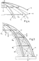
- two adjacent arch binders 14 form a shell field 20 which is curved in the curved plane of the calotte and tapers upwards in the form of an elongated spherical triangle in which four transverse rods 18 run, which are fixed on both arch binders 14.
- the ground clearance i 1 of a lower ring 19 consisting of cross bars 18 t is for example 4.7 m, the ground clearance i 2 of the next higher ring 19 m is about 8.7 m.
- Another ring 19 n is located above the latter at a distance q of 3 m.
- the four rings 19, 19 n , 19 m , 19 t recognizable in FIGS. 1, 2, with the arch obstructions 14 crossing them - within two arch binders 14 four - tapering fields 17, each of which intersect two Diagonal ropes 15 is spanned; the latter are fixed at the penetration points of the bow tie 14 / crossbar 18.
- Each of the shell fields 20 is fanned out by means of three web sections made of flexible material in the form of foils 22, 23, 24 made of translucent material; these foils 22, 23, 24 are clamped between their pair of binders 14 over their entire arc length b.
- the latter is pumped by means of low-pressure pneumatics, tensioning the foils 22 to 24 and thus produces a uniform large-area and flutter-proof infill in the form of a cushion 27 between the pairs of bow ties 14.
- Reinforcing cross cables 28 are placed on the outer film 22 and fastened on both ends in the area of the bow ties 14.
- the base section 30 of a metal profile rests as a rain gutter 31, which is held by fastening screws 34.
- the latter each pass through a pipe stub 35 with wing flaps 36.
- a cable eye 29 of the cross cable 28 is articulated by means of a bolt 38.
- Tensioning devices of the cross cables 28 and the diagonal cables 15 are not shown in the drawing for reasons of clarity.
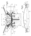
- the inclined side legs 32 of the rain drainage channel 31 each end end carry an extruded profile 40 made of an aluminum alloy, the cross-section of which consists of an L-shaped condensate drain channel 41 and a subsequent clamping profile 42; the latter not in an undercut groove 43 on the area of a longitudinal edge 21 of the outer film 22 and a clamping strip 44.
- the clamping strip 44 ensures the fixing of the tensioned outer film 22 in the clamping profile 42 of the connecting profile 40.
- the horizontal distance s between two outer films 22 in FIG. 6 is approximately 200 mm.
- connection profile 48 which is angularly shaped and on an edge of the bow tie 14 is fixed and secured by screws 47.
- This connecting profile 48 is - in its left-hand embodiment in FIG. 6 - equipped with two undercut grooves 49, 50 for connecting the central and inner foils 23, 24 and for receiving a clamping strip 44 in each case.
- the inner film 24 is provided with a welt edge 52 which runs in a welt groove 51 of the connecting profile 48 - whose height k 1 measures approximately 70 mm and its distance k 2 from the upper edge of the other connecting profile 40 approximately 80 mm.
- the outer and inner foils 22, 24 are each about 190 ⁇ m thick, while the middle foil 23 has a thickness of about 100 ⁇ m.
- the average values of the physical properties of the film used for a film thickness between 90 and 150 ⁇ m can be found in the following table:
- Fig. 7 shows an embodiment of a pillow 27 a
- the outer or upper air chamber 25 contains a standing air filling with overpressure
- the inner or lower air chamber 26 is flowed through by the interior of the building or by fluid from an air heating system according to arrow x.
- the alternative air heating system is indicated at 54, the intake and exhaust valves at 56.58.
- the air pressure in the lower air chamber 26 of preferably 20 mm WS can be controlled by the exhaust valve (s) 58.
- FIG. 8 9 also illustrate pillow constructions 27 b and 27 c with flowing air x in the lower air chamber 26.
- the upper air chamber 25 is shown in FIG. 8 by a valve 60 in the middle film 23 connected to the lower air chamber 26 so that a branch flow y of the fluid can fill the upper air chamber 25 with controlled air.
- 62 with a normally closed upper connection valve in the outer film 22 is designated.
- a surface air flow z heated from 54 a - coming from blowing nozzles 55 - can be guided along the bottom-facing surface 24 a of the inner film 24.
- FIG. 9 shows a membrane opening 64 at the location of the valve 60 described.
- the tie 14 shown here which according to FIG. 10 - not with a calotte roof - has an elongated rectangular cushion area parallel to a further tie 14, on the right a pair of connection profiles 66, 68, only indicated on the left side of the tie, can be seen, whose upper connection profile 66 undercut on both sides of a crease line 67 Has grooves 43.49.
- the lower connection profile 68 is seated on the binder 14 with the interposition of sealing strips 69 and holds the inner film 24 in its downward groove 51.
- Fig. 10 also shows that the connection profiles 68 - but also 40, 48, 66 - are also attached to the front ends of the pillow fields, to which the inlet valves 56 and the outlet valves 58 are assigned; these valves 56, 58 and 60, 62 can either be provided on both sides of a cross section according to FIGS. 5, 7, 8 or also at the ends of long pillow fields according to FIGS. 3, 10.
Landscapes
- Engineering & Computer Science (AREA)
- Architecture (AREA)
- Civil Engineering (AREA)
- Structural Engineering (AREA)
- Physics & Mathematics (AREA)
- Fluid Mechanics (AREA)
- Electromagnetism (AREA)
- Tents Or Canopies (AREA)
Claims (15)
- Bâtiment, notamment hall couvert, comportant une ossature à trois dimensions du type charpente, ainsi que deux pans de nappe (22, 24) souples en un matériau flexible, qui sont fixés l'un au-dessus de l'autre sur l'ossature entre deux poutres maîtresses voisines (14) de l'ossature, et qui délimitent un espace susceptible d'être alimenté par un fluide, adjacent aux poutres-maîtresses (14) et comportant au moins une entrée et une sortie pour le fluide, une nappe intermédiaire (23) en une matière plastique flexible s'étendant entre les deux pans de nappe et séparant l'une de l'autre deux chambres (25, 26) qui présentent une pression intérieure différente de la pression atmosphérique, caractérisé en ce qu'une chambre (25) est remplie de fluide soufflé au repos et l'autre chambre (26) est traversée par un fluide soufflé (x) en écoulement entre l'entrée (56) et la sortie (58).
- Bâtiment, notamment hall couvert, comportant une ossature à trois dimensions, ainsi que deux pans de nappe (22, 24) en un matériau flexible, qui sont fixés l'un au-dessus de l'autre sur l'ossature entre deux poutres maîtresses voisines (14) de l'ossature, et qui délimitent un espace susceptible d'être alimenté par un fluide, adjacent aux poutres-maîtresses (14) et comportant au moins une entrée et une sortie pour le fluide, une nappe intermédiaire (23) en une matière plastique flexible s'étendant entre les deux pans de nappe et séparant l'une de l'autre deux chambres (25, 26) qui présentent une pression intérieure différente de la pression atmosphérique, caractérisé en ce que l'une (26) des chambres agencées entres les nappes de feuille (22 à 24) est traversée, à partir d'une entrée (56), par un écoulement de fluide soufflé (x), et est reliée à l'autre chambre (25) au moyen d'au moins une soupape (60) ou d'au moins un orifice de passage (64) dans la nappe intermédiaire (23) pour créer un écoulement dérivé (y) du fluide soufflé, une soupape (58, 62) dans l'autre pan de nappe (22) de la chambre (25) étant associée à la soupape ou à l'orifice de passage de la nappe intermédiaire, en tant que sortie.
- Bâtiment selon la revendication 1, caractérisé en ce que la chambre (25) remplie de fluide soufflé au repos, est la chambre située à l'extérieur, à savoir la chambre supérieure.
- Bâtiment selon l'une des revendications 1 à 3, caractérisé en ce que le fluide soufflé (x) peut être amené à la chambre (26) au moyen d'un système de chauffage d'air (54).
- Bâtiment selon l'une des revendications 1 à 4, caractérisé en ce qu'en-dessous de la feuille intérieure ou inférieure (24), sont prévues, au niveau de la surface (24a) de la feuille, des buses de soufflage (55) ou dispositifs analogues destinés à engendrer un écoulement d'air (Z).
- Bâtiment selon l'une des revendications 1 à 5, caractérisé en ce que chacune des feuilles formant les pans de nappe (22, 24) ainsi que la nappe intermédiaire (23), sont fixées par leurs bords (21), de manière amovible et étanche à l'air, sur des profilés de raccordement distincts (40, 48; 66, 68) des poutres maîtresses (14).
- Bâtiment selon la revendication 6, caractérisé en ce que les profilés de raccordement délimitent partiellement la ou les chambre(s) (25; 26), et/ou sont disposés de manière amovible sur la poutre maîtresse (14).
- Bâtiment selon l'une des revendications 1 à 7, caractérisé en ce que les poutres maîtresses (14) sont fixées au sol par l'une de leurs extrémités, et s'étendent vers un élément de liaison (16) disposé à une distance (h) du sol (12) et auquel elles sont raccordées par leur autre extrémité.
- Bâtiment selon l'une des revendications 1 à 8, caractérisé en ce que les poutres maîtresses (14) sont fixées au sol (12) selon un agencement sensiblement circulaire et sont cintrées en direction d'un anneau central de toit (16) en formant une ossature en forme de coupole, les feuilles (22, 23, 24) entre chaque paire de poutres maîtresses voisines formant un coussin d'air à double enveloppe en forme de triangle sphérique.
- Bâtiment selon l'une au moins des revendications 1 à 9, caractérisé en ce que les poutres maîtresses (14) sont reliées entre-elles par des traverses (18), des tirants en diagonale étant disposés sensiblement aux points formant les coins des panneaux délimités par les poutres maîtresses (14) et les traverses (18).
- Bâtiment selon l'une des revendications 1 à 10, caractérisé en ce que sur la poutre maîtresse (14) est fixé un profilé en forme de gouttière (31) qui s'étend sur la poutre maîtresse en direction longitudinale, et/ou en ce que de la poutre maîtresse (14) font saillie vers le haut, des vis de fixation (34) sur lesquelles sont accrochés des câbles transversaux (28) reposant partiellement sur la feuille extérieure (22).
- Bâtiment selon l'une des revendications 1 à 11, caractérisé en ce que sur chacun des bords longitudinaux du profilé en forme de gouttière (31) est rapporté un profilé de raccordement (40) auquel peut être associé un autre profilé de raccordement (48, 66) sur la poutre maîtresse (14), à une distance (k₂) du bord supérieur du premier profilé de raccordement (40, 68).
- Bâtiment selon l'une des revendications 1 à 12, caractérisé en ce que le profilé de raccordement (40) comporte au moins une rainure en contre-dépouille (43) ouverte vers le haut ainsi qu'une partie de profilé en gouttière (41) qui s'y raccorde et dirigée vers le haut, et/ou en ce que le profilé de raccordement (48, 66) est pourvu d'au moins deux rainures en contre-dépouille (49, 50, 51) s'étendant à distance l'une de l'autre, des organes d'étanchéité (69) étant prévus entre les profilés de raccordement (40; 48; 66; 68) et/ou entre un profilé de raccordement et un élément de construction le supportant.
- Bâtiment selon l'une des revendications 1 à 13, caractérisé en ce que le profilé de raccordement (48) est réalisé sous forme d'élément de cornière à chaque aile duquel est associée une rainure (49, 50; 49, 51), et/ou en ce que dans chacune des rainures en contre-dépouille (43, 49, 50, 51) du/des profilé/s de raccordement (40, 48; 66, 68) est fixé de manière étanche un bord de feuille (21), au moyen d'un organe de serrage (44, 52).
- Bâtiment selon l'une au moins des revendications 1 à 14, caractérisé par une épaisseur de feuille de 50 µm à 250 µm, de préférence entre 80 µm et 200 µm, et/ou par des feuilles (22, 23, 24) en un copolymère modifié d'éthylène-tétrafluoréthylène.
Applications Claiming Priority (2)
| Application Number | Priority Date | Filing Date | Title |
|---|---|---|---|
| DE8806173U | 1988-05-09 | ||
| DE8806173 | 1988-05-09 |
Publications (2)
| Publication Number | Publication Date |
|---|---|
| EP0342147A1 EP0342147A1 (fr) | 1989-11-15 |
| EP0342147B1 true EP0342147B1 (fr) | 1993-03-31 |
Family
ID=6823895
Family Applications (1)
| Application Number | Title | Priority Date | Filing Date |
|---|---|---|---|
| EP89710040A Expired - Lifetime EP0342147B1 (fr) | 1988-05-09 | 1989-05-09 | Construction avec chambres admettant un fluide |
Country Status (3)
| Country | Link |
|---|---|
| US (1) | US5027564A (fr) |
| EP (1) | EP0342147B1 (fr) |
| DE (2) | DE58903910D1 (fr) |
Families Citing this family (24)
| Publication number | Priority date | Publication date | Assignee | Title |
|---|---|---|---|---|
| DE60113864T2 (de) * | 2000-10-10 | 2006-07-20 | Wizzoz Pty Ltd. | Kopplungsvorrichtung |
| AT410621B (de) * | 2001-09-19 | 2003-06-25 | Felix Heescher Gmbh | Abschattungs- und/oder isolierbahn, sowie verfahren zur herstellung und deren verwendung |
| GB2387183B (en) * | 2002-04-02 | 2005-07-27 | Vector Special Projects Ltd | Building component |
| US7406802B2 (en) * | 2003-03-19 | 2008-08-05 | Awi Licensing Company | Panel structures and mounting therefore |
| CN1787736B (zh) * | 2003-06-23 | 2010-07-21 | 旭硝子绿色技术株式会社 | 透明树脂薄膜制屋顶及配置它的建筑物 |
| EP1989377A1 (fr) * | 2005-12-23 | 2008-11-12 | Prospective Concepts AG | Element de construction pneumatique et toit construit a partir de celui-ci |
| DE102007001376B4 (de) * | 2007-01-09 | 2009-04-16 | Greiner, Switbert, Dr. | Membranelement und Verfahren zum Verkleiden von Flächen |
| EP2022906B1 (fr) * | 2007-07-31 | 2010-05-12 | MI-Technologies GmbH | Elément de feuille |
| JP5003670B2 (ja) * | 2007-12-27 | 2012-08-15 | 大成建設株式会社 | 建物の外被構造 |
| US20100006089A1 (en) * | 2008-07-14 | 2010-01-14 | Mi-Technologies Gmbh | Film element |
| DE102008050457A1 (de) * | 2008-10-08 | 2010-04-29 | Elnic Gmbh | Verfahren zur Wiederverwendung von gebrauchter Stützluft für Folienkissenvorrichtungen, die als bauelemente für Dach- und/oder Fassadenkonstruktionen bestimmt sind. |
| DE202010011855U1 (de) | 2010-08-25 | 2011-03-24 | Off, Robert, Prof. Dr.-Ing. | Vorrichtung zur thermischen Konditionierung von Gebäuden |
| DE202010015743U1 (de) * | 2010-11-24 | 2012-03-01 | Vector Foiltec Gmbh | Gebäudeumhüllungselement mit thermischem Isolierelement |
| US8336261B2 (en) | 2010-11-29 | 2012-12-25 | Qatar Football Association | Revolving roof for an indoor/outdoor stadium |
| US8215066B2 (en) * | 2010-11-29 | 2012-07-10 | Qatar Football Association | Multi-layer, revolving stadium roof |
| WO2012073064A1 (fr) * | 2010-11-29 | 2012-06-07 | Qatar Football Association | Toit de stade tournant multicouche |
| US8555557B2 (en) * | 2010-11-29 | 2013-10-15 | Qatar Football Association | Indoor/outdoor stadium system for energy use reduction |
| US8387315B2 (en) * | 2010-11-29 | 2013-03-05 | Qatar Football Association | Microclimate cooling system for an indoor/outdoor stadium |
| WO2012073062A1 (fr) * | 2010-11-29 | 2012-06-07 | Qatar Football Association | Système de stade intérieur/extérieur pour réduction d'utilisation d'énergie |
| DE102010055462A1 (de) * | 2010-12-21 | 2012-06-21 | Greiner & Gutmann Gbr | Verkleidung |
| FR2996954B1 (fr) * | 2012-10-15 | 2014-12-05 | Commissariat Energie Atomique | Detecteur courbe de particules gazeux |
| DE202012104310U1 (de) * | 2012-11-09 | 2014-02-11 | JOPE Beteiligungs GmbH | Tragluftdach für einen Biogasbehälter |
| CN103255944B (zh) * | 2013-05-17 | 2015-04-08 | 合肥通用机械研究院 | 局部双层球面网壳储罐拱顶结构 |
| US11686104B2 (en) * | 2019-09-13 | 2023-06-27 | Hendrick Screen Company | Flexible, profile bar screen |
Family Cites Families (14)
| Publication number | Priority date | Publication date | Assignee | Title |
|---|---|---|---|---|
| US2986150A (en) * | 1958-03-17 | 1961-05-30 | Torian William Harold | Means for mounting thin, flexible membranes |
| DE2052864A1 (fr) * | 1970-10-21 | 1972-03-09 | ||
| US3791076A (en) * | 1971-12-27 | 1974-02-12 | Smith X S Inc | Plastic covered building structures |
| DE2228389C2 (de) * | 1972-06-10 | 1974-01-03 | L. Stromeyer & Co, Gmbh, 7750 Konstanz | Baukonstruktion mit einem Gerüst und einer durch Druck gespannten Haut |
| DE2724373A1 (de) * | 1977-05-28 | 1978-11-30 | Alfred Hochstein | Aufblasbares bauwerk |
| DE3011308A1 (de) * | 1980-03-24 | 1981-10-01 | Rüdiger 4807 Borgholzhausen Vogler | Pneumatisch steuerbares, isolierendes form- und flaechenelement |
| US4452230A (en) * | 1980-05-23 | 1984-06-05 | Nelson Richard C | Canopy system for a building structure |
| GB2115032A (en) * | 1982-02-22 | 1983-09-01 | Dean And Dyball Limited | Roof structure or cover |
| DE3271948D1 (en) * | 1982-10-14 | 1986-08-14 | Canada Inc 116736 | Canopy system for a building structure |
| US4583331A (en) * | 1983-12-27 | 1986-04-22 | Clamshell Partners Ltd. | Frame supported structure with tensioned fabric panels |
| DE3426027A1 (de) * | 1984-07-14 | 1986-01-23 | Mero-Raumstruktur GmbH & Co Würzburg, 8700 Würzburg | Vorrichtung zur abgedichteten befestigung von biegsamen abdeckstreifen fuer einfach oder doppelt gekruemmte dachflaechen von gebaeuden |
| US4878322A (en) * | 1987-08-10 | 1989-11-07 | Ikege, Inc. | Insulating plastic film structures and method |
| EP0306717A1 (fr) * | 1987-08-10 | 1989-03-15 | George Ikeda | Structures isolantes de pellicules plastiques ainsi que procédé |
| US4807405A (en) * | 1987-08-20 | 1989-02-28 | Borgquist Ronald B | Geodesic inflatable structure, and methods of constructing and utilizing same |
-
1989
- 1989-05-04 US US07/347,759 patent/US5027564A/en not_active Expired - Fee Related
- 1989-05-09 DE DE8989710040T patent/DE58903910D1/de not_active Expired - Fee Related
- 1989-05-09 DE DE8905789U patent/DE8905789U1/de not_active Expired - Lifetime
- 1989-05-09 EP EP89710040A patent/EP0342147B1/fr not_active Expired - Lifetime
Also Published As
| Publication number | Publication date |
|---|---|
| DE58903910D1 (de) | 1993-05-06 |
| EP0342147A1 (fr) | 1989-11-15 |
| DE8905789U1 (de) | 1990-06-21 |
| US5027564A (en) | 1991-07-02 |
Similar Documents
| Publication | Publication Date | Title |
|---|---|---|
| EP0342147B1 (fr) | Construction avec chambres admettant un fluide | |
| DE2113407C3 (de) | Traglufthalle | |
| DE2206819B2 (de) | Bauwerk zum lagern von ausruestungsgegenstaenden oder betriebsmitteln | |
| CH661765A5 (de) | Dachfirst mit belueftung. | |
| DE1904152A1 (de) | Dach | |
| DE29500055U1 (de) | Haltevorrichtung zum Verankern ein- oder mehrlagiger Bahnen an einem ortsfesten Bauteil | |
| DE2347136A1 (de) | Selbsttragendes dachelement fuer gebaeude sowie durch vereinigung mehrerer derartiger elemente erhaeltliches gebaeudedach | |
| DE202014008425U1 (de) | Wetterschutzmodul und Wetterschutzvorrichtung aus derartigen Wetterschutzmodulen | |
| DE2059832A1 (de) | Gewaechshaus mit einem Traggeruest und zumindest ueberwiegend durchsichtigen oder durchscheinenden Wand- und/oder Bedachungselementen | |
| EP1250835B1 (fr) | Serre | |
| WO2003046454A1 (fr) | Sechoir pour le sechage en continu de produits alimentaires | |
| DE20109417U1 (de) | Hochwassersperre aus Systemboxen | |
| DE29616791U1 (de) | An ein Baugerüst anbringbare Witterungsschutzeinrichtung | |
| DE2146286C2 (de) | Wetter- und Sichtschutzschild | |
| DE2052190A1 (de) | Gewachshaus | |
| DE2853268A1 (de) | Mehrkammerfolie und verfahren zu ihrer herstellung | |
| DE2429661A1 (de) | Vorrichtung zum abstuetzen von grabenwaenden | |
| EP1726745A1 (fr) | couverture permettant le passage de la lumiere et de l'air | |
| CH675611A5 (fr) | ||
| DE1684856C (de) | Halle mit lichtdurchlässigen Dach elementen aus glasfaserverstärktem Kunst | |
| DE202004011616U1 (de) | Foliendach für ein Gewächshaus | |
| DE1759459A1 (de) | Bauelement fuer doppelwandige Bauwerke und aus solchen Bauelementen bestchendes Bauwerk | |
| DE804860C (de) | Transportables Gewaechshaus o. dgl. | |
| DE19640915C1 (de) | Plattform für eine Parkanlage | |
| DE3315318A1 (de) | Selbsttragendes bauelement grosser laenge fuer eine gebaeudeabdeckung |
Legal Events
| Date | Code | Title | Description |
|---|---|---|---|
| PUAI | Public reference made under article 153(3) epc to a published international application that has entered the european phase |
Free format text: ORIGINAL CODE: 0009012 |
|
| AK | Designated contracting states |
Kind code of ref document: A1 Designated state(s): AT BE CH DE ES FR GB GR IT LI LU NL SE |
|
| RBV | Designated contracting states (corrected) |
Designated state(s): CH DE FR GB IT LI NL SE |
|
| 17P | Request for examination filed |
Effective date: 19900410 |
|
| 17Q | First examination report despatched |
Effective date: 19910327 |
|
| GRAA | (expected) grant |
Free format text: ORIGINAL CODE: 0009210 |
|
| AK | Designated contracting states |
Kind code of ref document: B1 Designated state(s): CH DE FR GB IT LI NL SE |
|
| PG25 | Lapsed in a contracting state [announced via postgrant information from national office to epo] |
Ref country code: SE Effective date: 19930331 |
|
| REF | Corresponds to: |
Ref document number: 58903910 Country of ref document: DE Date of ref document: 19930506 |
|
| ITF | It: translation for a ep patent filed | ||
| GBT | Gb: translation of ep patent filed (gb section 77(6)(a)/1977) |
Effective date: 19930526 |
|
| ET | Fr: translation filed | ||
| PLBE | No opposition filed within time limit |
Free format text: ORIGINAL CODE: 0009261 |
|
| STAA | Information on the status of an ep patent application or granted ep patent |
Free format text: STATUS: NO OPPOSITION FILED WITHIN TIME LIMIT |
|
| 26N | No opposition filed | ||
| PGFP | Annual fee paid to national office [announced via postgrant information from national office to epo] |
Ref country code: GB Payment date: 19950418 Year of fee payment: 7 |
|
| PGFP | Annual fee paid to national office [announced via postgrant information from national office to epo] |
Ref country code: CH Payment date: 19950616 Year of fee payment: 7 |
|
| PG25 | Lapsed in a contracting state [announced via postgrant information from national office to epo] |
Ref country code: GB Effective date: 19960509 |
|
| PG25 | Lapsed in a contracting state [announced via postgrant information from national office to epo] |
Ref country code: LI Effective date: 19960531 Ref country code: CH Effective date: 19960531 |
|
| GBPC | Gb: european patent ceased through non-payment of renewal fee |
Effective date: 19960509 |
|
| REG | Reference to a national code |
Ref country code: CH Ref legal event code: PL |
|
| PGFP | Annual fee paid to national office [announced via postgrant information from national office to epo] |
Ref country code: FR Payment date: 19970516 Year of fee payment: 9 |
|
| PGFP | Annual fee paid to national office [announced via postgrant information from national office to epo] |
Ref country code: NL Payment date: 19970529 Year of fee payment: 9 |
|
| PGFP | Annual fee paid to national office [announced via postgrant information from national office to epo] |
Ref country code: DE Payment date: 19971029 Year of fee payment: 9 |
|
| PG25 | Lapsed in a contracting state [announced via postgrant information from national office to epo] |
Ref country code: FR Free format text: LAPSE BECAUSE OF NON-PAYMENT OF DUE FEES Effective date: 19980531 |
|
| PG25 | Lapsed in a contracting state [announced via postgrant information from national office to epo] |
Ref country code: NL Free format text: LAPSE BECAUSE OF NON-PAYMENT OF DUE FEES Effective date: 19981201 |
|
| NLV4 | Nl: lapsed or anulled due to non-payment of the annual fee |
Effective date: 19981201 |
|
| PG25 | Lapsed in a contracting state [announced via postgrant information from national office to epo] |
Ref country code: DE Free format text: LAPSE BECAUSE OF NON-PAYMENT OF DUE FEES Effective date: 19990302 |
|
| REG | Reference to a national code |
Ref country code: FR Ref legal event code: ST |
|
| PG25 | Lapsed in a contracting state [announced via postgrant information from national office to epo] |
Ref country code: IT Free format text: LAPSE BECAUSE OF NON-PAYMENT OF DUE FEES;WARNING: LAPSES OF ITALIAN PATENTS WITH EFFECTIVE DATE BEFORE 2007 MAY HAVE OCCURRED AT ANY TIME BEFORE 2007. THE CORRECT EFFECTIVE DATE MAY BE DIFFERENT FROM THE ONE RECORDED. Effective date: 20050509 |