EP0341902B1 - Programmierungsschnittstelle für Hörgeräte - Google Patents
Programmierungsschnittstelle für Hörgeräte Download PDFInfo
- Publication number
- EP0341902B1 EP0341902B1 EP89304486A EP89304486A EP0341902B1 EP 0341902 B1 EP0341902 B1 EP 0341902B1 EP 89304486 A EP89304486 A EP 89304486A EP 89304486 A EP89304486 A EP 89304486A EP 0341902 B1 EP0341902 B1 EP 0341902B1
- Authority
- EP
- European Patent Office
- Prior art keywords
- programming
- hearing aid
- battery
- electrode
- coupling member
- Prior art date
- Legal status (The legal status is an assumption and is not a legal conclusion. Google has not performed a legal analysis and makes no representation as to the accuracy of the status listed.)
- Expired - Lifetime
Links
Images

Classifications
-
- H—ELECTRICITY
- H04—ELECTRIC COMMUNICATION TECHNIQUE
- H04R—LOUDSPEAKERS, MICROPHONES, GRAMOPHONE PICK-UPS OR LIKE ACOUSTIC ELECTROMECHANICAL TRANSDUCERS; ELECTRIC HEARING AIDS; PUBLIC ADDRESS SYSTEMS
- H04R25/00—Electric hearing aids
- H04R25/55—Electric hearing aids using an external connection, either wireless or wired
- H04R25/556—External connectors, e.g. plugs or modules
-
- H—ELECTRICITY
- H04—ELECTRIC COMMUNICATION TECHNIQUE
- H04R—LOUDSPEAKERS, MICROPHONES, GRAMOPHONE PICK-UPS OR LIKE ACOUSTIC ELECTROMECHANICAL TRANSDUCERS; ELECTRIC HEARING AIDS; PUBLIC ADDRESS SYSTEMS
- H04R25/00—Electric hearing aids
- H04R25/43—Electronic input selection or mixing based on input signal analysis, e.g. mixing or selection between microphone and telecoil or between microphones with different directivity characteristics
-
- H—ELECTRICITY
- H04—ELECTRIC COMMUNICATION TECHNIQUE
- H04R—LOUDSPEAKERS, MICROPHONES, GRAMOPHONE PICK-UPS OR LIKE ACOUSTIC ELECTROMECHANICAL TRANSDUCERS; ELECTRIC HEARING AIDS; PUBLIC ADDRESS SYSTEMS
- H04R2225/00—Details of deaf aids covered by H04R25/00, not provided for in any of its subgroups
- H04R2225/39—Aspects relating to automatic logging of sound environment parameters and the performance of the hearing aid during use, e.g. histogram logging, or of user selected programs or settings in the hearing aid, e.g. usage logging
-
- H—ELECTRICITY
- H04—ELECTRIC COMMUNICATION TECHNIQUE
- H04R—LOUDSPEAKERS, MICROPHONES, GRAMOPHONE PICK-UPS OR LIKE ACOUSTIC ELECTROMECHANICAL TRANSDUCERS; ELECTRIC HEARING AIDS; PUBLIC ADDRESS SYSTEMS
- H04R2225/00—Details of deaf aids covered by H04R25/00, not provided for in any of its subgroups
- H04R2225/41—Detection or adaptation of hearing aid parameters or programs to listening situation, e.g. pub, forest
-
- H—ELECTRICITY
- H04—ELECTRIC COMMUNICATION TECHNIQUE
- H04R—LOUDSPEAKERS, MICROPHONES, GRAMOPHONE PICK-UPS OR LIKE ACOUSTIC ELECTROMECHANICAL TRANSDUCERS; ELECTRIC HEARING AIDS; PUBLIC ADDRESS SYSTEMS
- H04R25/00—Electric hearing aids
- H04R25/60—Mounting or interconnection of hearing aid parts, e.g. inside tips, housings or to ossicles
- H04R25/602—Mounting or interconnection of hearing aid parts, e.g. inside tips, housings or to ossicles of batteries
Definitions
- the present invention relates generally to hearing aid devices, and more particularly to an arrangement forfaci litating the direct connection of an external programming system to the circuitry inside a hearing aid.
- Programmable hearing aids such as the hearing aid disclosed in U.S. Patent No. 4,425,481 (Mangold et al., 1984) can store a number of distinct programs, or sets of parameter values, each designed for use in different audio environments. For instance, a hearing aid with eight distinct programs could have programs for a variety of correspondingly distinct situations, such as conversing with one person in a quiet room, conversing with several persons in an otherwise fairly quiet environment, conversing with one or more persons in settings with increasing levels of background noise, walking or commuting environments with large noise variations, listening to music in a quiet room, and listening to music in a noisy environment.
- a programmable hearing aid must be customized to compensate for an individual's particular hearing deficiencies.
- some aspects of hearing aid programming are inherently subjective on the part of the user - and therefore hearing aids often must be reprogrammed several times before an optimal set of programs is found.
- a person's hearing characteristics may change over time, requiring adjustment of the programs stored in a programmable hearing aid. As a result, programmable hearing aids should be easily reprogrammed.
- One problem associated with the design of programmable hearing aids is balancing the competing objectives of miniaturization and providing a convenient interface for connecting the device to an external programming system for reprogramming the device.
- a major objective in the design of hearing aids is designing very small devices, and the size of new hearing aid models is decreasing with the development of miniaturized circuitry.
- a programmable hearing aid device could be programmed by remote control.
- a hearing aid could be programmed by wireless transmission of hearing aid parameters using either ultrasonic or radio frequency transmission techniques.
- ultrasonic and radio frequency transmission methods suffer from at least one major problem: the need for added circuitry to detect and decode the programming signals. While this problem is not insurmountable, it does increase the amount of circuitry needed in the hearing aid, and generally increases the cost of the hearing aid and the associated programming circuitry.
- the present invention has the advantage of providing a direct electrical connection for programming a hearing aid, and yet it avoids the need for an external port devoted solely to the programming function. In addition, no added circuitry is need to detect and decode programming signals.
- a programmable hearing aid comprising a battery compartment having two battery terminals for contacting the positive and negative terminals of a battery, said battery terminals electrically coupled to circuitry in the programmable hearing aid, programming circuitry in the hearing aid, and a programming terminal coupled to said programming circuitry, characterised by said programming terminal being located in said battery compartment, said programming circuitry being coupled to said battery terminals, and said battery compartment and programming terminal being physically arranged such that said programmable terminal is utilizable only when said battery is removed from said battery compartment.
- an apparatus for establishing electrical contact between a programmable hearing aid and an external hearing aid programming system said programmable hearing aid including programming circuitry, a programming terminal coupled to said programming circuitry and a battery compartment having battery terminals connected to said programming circuitry, said apparatus comprising a coupling member having a positive electrode, a negative electrode and a programming electrode, wherein said programming electrode can be electrically connected to an external hearing aid programming system, said coupling member adapted for contacting said battery terminals with said positive and negative electrodes and for contacting said programming terminal with said programming electrode, characterised by said coupling member being sized to fit in said battery compartment such that when said coupling member is mounted therein, said positive and negative electrodes are in electrical contact with said battery terminals and said programming electrode is in electrical contact with said programming terminal, inside the battery compartment.
- a method of programming a programmable hearing aid energizable by a battery retained in a battery compartment having battery terminals, said programmable hearing aid having programming circuitry and a programming terminal coupled to said programming circuitry comprising connecting an external hearing aid programming system to the programming terminal by providing a coupling member having a positive electrode, a negative electrode, and a programming electrode in electrical contact with the external hearing aid programming system, and by contacting the battery terminals with said positive and negative electrodes and contacting the programming terminal with said programming electrode, characterised by locating the programming terminal in the battery compartment in the hearing aid such that said programming terminal is utilizable only when said battery is removed from said battery compartment, inserting said coupling member into said battery compartment so as to electrically contact said programming electrode with the programming terminal in the battery compartment, providing power to said programming circuitry through said positive and negative electrodes and said battery terminals, and providing programming signals to said programming circuitry through said programming electrode and programming terminal.
- a programmable hearing aid having a battery compartment which normally holds a battery cell.
- a pair of battery terminals in the battery compartment electrically couples a battery positioned in the compartment to the hearing aid's functional circuitry.
- a programming terminal located in the battery compartment is situated so that it contacts a battery or other object situated in the battery compartment.
- the programming terminal is also electrically coupled to the hearing aid's internal programming circuitry.
- a set of three electrical wires connected to the programming device are brought into contact with the battery and programming terminals in the battery compartment via a coupling member shaped to fit in the battery compartment and having electrodes arranged for contacting the battery and programming terminals in the battery compartment when the coupling member is retained within the battery compartment.
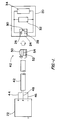
- the present invention concerns a system for coupling a hearing aid 20 to an external hearing aid programming system 22. Since the hearing aid 20 is normally battery powered, hearing aid device 20 has a battery compartment 24 for holding a standard hearing aid battery. As is standard, two battery terminals 26 and 28 are located in the battery compartment 24 for contacting the positive (+) and negative (-) terminals of a battery.
- a programming terminal 30 in battery compartment 24 that is coupled to programming circuitry 32 inside the hearing aid.
- a battery is placed inside the battery compartment, supplying power to the hearing aid's internal circuitry 34.
- Programming terminal 30 is preferably located so that during normal hearing aid operation when a battery is in place in the battery compartment, the programming terminal contacts the positive voltage battery terminal. This arrangement obviates the need for connecting the programming terminal to the positive voltage battery terminal through a resistor, and thus avoids dissipation of power during normal operation.
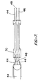
- a coaxial connector42 carrying three leads 44, 46, and 48 (also denoted +, - and P, respectively) connects the external programming system 22 to hearing aid 20 via coupling member 40.
- Two of the leads 44 and 46 provide a voltage potential for providing power to hearing aid 20, equivalent to the voltage potential normally provided by a battery.
- the third lead 48 carries programming signals and reply signals which convey information from the external programming system 22 to the hearing aid 20 and also from the hearing aid 20 to the programming system 22.
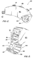
- FIG. 2 illustrates a programmable hearing aid according to the present invention, the main body of which is designed to fit behind a person's ear.
- Hearing aid housing 60 encloses the internal and programming circuitry for the hearing aid and is connected via tubing 62 to an earpiece (not shown) which is inserted in the wearer's ear.
- Appropriate external control means generally designated 61 and 63, and adjustable external control means 65 are provided in contact with internal hearing aid circuitry for adjustment of various hearing aid parameters, as is known in the art.
- battery compartment 24 is preferably located between two side walls of housing 60 at the end of the housing opposite the attachment of tubing 62.
- Battery compartment door 64 is hinged along pivot axis 66 for adjustment between a closed position within the battery compartment, as shown in Figure 2, and an open, access position as shown in Figure 3.
- Battery compartment 24 and battery compartment door 64 are preferably generally cylindrical.
- the battery compartment door preferably comprises arcuate outer wall 68 and arcuate inner wall 69 which form, in combination, a generally cylindrical battery recess.
- Outerwall 68 of the battery compartment door preferably includes shoulder 73 projecting interiorly therefrom which serves as a stop to retain the battery or programming coupler in the battery compartment door.
- Ribs 59 may be provided on an inner surface of the battery compartment door for securely retaining the battery or the coupling member. Access to battery compartment 24 may be obtained by exerting pressure at raised surface 67 to rotate battery compartment door 64 about its pivot axis 66.
- Battery terminals 26 and 28 are preferably located generally opposite one another and adjacent interior surfaces of housing 60 in battery compartment 24. The battery terminals are positioned to contact the corresponding battery electrodes when a battery is loaded into the battery compartment and the battery compartment door is closed. Suitable types of battery terminals are well known in the art.
- Figure 3 illustrates a preferred embodiment of programming terminal 30 projecting into the battery compartment.
- Programming terminal 30 is electrically connected to the programming circuitry in hearing aid 20, and it is positioned in the battery compartment to contact the programming electrode on programming coupling member 40 when the coupling member is inserted in the battery compartment and the battery compartment door is closed.
- slot 71 is provided in inner wall 69 of the battery compartment door for passage of the programming electrode when the battery compartment door is in the closed position. As the battery compartment door is closed by rotation about pivot axis 66, programming terminal 30 projects through slot 71 and is positioned to contact the battery or the coupling member.
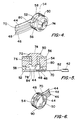
- FIGS 4-6 illustrate preferred embodiments of a generally disc-shaped coupling member 40 operatively engaged with coaxial connector 42.
- Coupling member 40 is sized to correspond generally to the configuration and dimensions of battery compartment 24.
- Electrodes 50 and 52 are provided on an outer surface of coupling member 40 for contacting battery terminals 26 and 28 provided in the battery compartment.
- programming electrode 54 is provided on an outer surface of coupling member 40 for contacting programming terminal 30 in the battery compartment.
- positive electrode 50 preferably comprises an outer portion 72 including generally flat contact surface 74, and a mounting pin 76 projecting generally centrally from the outer portion.
- Programming electrode 54 has a generally annular structure, including an outer contact surface 80.
- Positive electrode 50 and programming electrode 54 are electrically insulated from one another by means of non-conductive insulating element 56 interposed between the positive and programming electrodes.
- Negative electrode 52 includes a generally flat contact surface 84, and it is electrically insulated from programming electrode 54 by means of annular, non-conductive insulating element 58.
- the electrodes and insulating elements are preferably bonded to one another by suitable adhesives, and internal cavity 78 is preferably fitted with an inert, non-conductive material such as a silicone adhesive.
- Positive electrode 50, negative electrode 52, and programming electrode 54 are in electrical contact with the corresponding leads 44, 46 and 48, respectively, from coaxial cable 42.
- leads 44, 46 and 48 emerge from shielded coaxial cable 42 and are embedded in a substantially flat, non-conductive strip 70.
- Non-conductive strip 70 preferably comprises a thin, flexible, non-conductive film layer or the like. Suitable flexible, non-conductive materials are well known in the art.
- a non-conductive casing 82 may additionally be provided between cable 42 and strip 70 to insulate the electrical leads. Leads 44,46 and 48 emerge from the non-conductive strip at the end opposite cable 42 for connection to the appropriate electrodes on coupling member 40.
- Non-conductive strip 70 carrying leads 44, 46 and 48 is mounted between insulating element 58 and negative electrode 52 in the embodiment of coupling member 40 illustrated in Figures 4 and 5. As shown in Figure 5, electrical leads 44,46 and 48 project from the non-conductive strip 70 inside coupling member 40, and are electrically contacted to the corresponding electrodes in coupling member40, as shown. Positive lead 44 is electrically connected to positive electrode 50; negative lead 46 is electrically connected to negative electrode 52; and programming lead 48 is electrically connected to programming electrode 54.
- Non-conductive strip 70 facilitates electrical connection of lead wires from the coaxial cable to the appropriate electrodes in the coupling member.
- FIG 6 illustrates an alternative embodiment of coupling member 40 wherein the battery and programming electrodes are provided on the surface of an insulating member 90
- Figure 8 illustrates a contact arrangement for use with insulating member 90
- Insulating member 90 preferably comprises a single piece of non-conductive insulating material having dimensions corresponding generally to the dimensions of battery compartment 24
- Contact arrangement 88 is an extension of non-conductive strip 70 having the battery and programming lead wires embedded therein.
- lead wires 44, 46 and 48 are carried in a flexible, non-conductive layer, and each lead wire terminates in an electrode.
- Positive lead wire 44 is embedded in the flexible, non-conductive layer, and it terminates in a generally flat, circular positive electrode 50 which is carried on the surface of the non-conductive layer.
- Negative lead wire 46 likewise terminates in a generally flat, circular negative electrode 52 carried on the surface of the non-conductive layer.
- Programming lead wire 48 preferably terminates in programming electrode strip 54 carried on the surface of the non-conductive layer.
- Contact arrangement 88 is affixed to the exterior surface of insulating member 90, with a suitable adhesive, to position the positive, negative and programming electrodes at locations to contact the corresponding battery and programming terminals in the battery compartment.
- positive electrode 50 is affixed to a positive contact surface
- programming electrode 54 is affixed to the circumferential surface of insulating member 90.
- Negative electrode 52 is preferably affixed to the generally flat lower surface of insulating member 90.
- the embodiment of coupling member 40 illustrated in Figure 6 thus has a simplified construction wherein the lead wires are in direct electrical contact with the corresponding electrodes, and the flexible film carrying the lead wires and the electrodes is bonded to the outer surface of the insulating member.
- the programmable hearing aid device of the present invention is illustrated as a "behind-the-ear” type of hearing aid device, the present invention is equally applicable to "in-the-ear” hearing aid devices, in which the hearing aid components and housing are retained in the wearer's ear.
- the present invention has been described with reference to a single programming terminal and a single programming electrode, multiple programming terminals and corresponding programming electrodes may be provided in accordance with the present invention.
- programming terminals having a variety of configurations may be used according to the present invention.
Landscapes
- Engineering & Computer Science (AREA)
- Health & Medical Sciences (AREA)
- General Health & Medical Sciences (AREA)
- Neurosurgery (AREA)
- Otolaryngology (AREA)
- Physics & Mathematics (AREA)
- Acoustics & Sound (AREA)
- Signal Processing (AREA)
- Computer Networks & Wireless Communication (AREA)
- Battery Mounting, Suspending (AREA)
- Power Sources (AREA)
Claims (15)
dadurch gekennzeichnet,
Applications Claiming Priority (2)
| Application Number | Priority Date | Filing Date | Title |
|---|---|---|---|
| US07192242 US4961230B1 (en) | 1988-05-10 | 1988-05-10 | Hearing aid programming interface |
| US192242 | 1988-05-10 |
Publications (4)
| Publication Number | Publication Date |
|---|---|
| EP0341902A2 EP0341902A2 (de) | 1989-11-15 |
| EP0341902A3 EP0341902A3 (de) | 1991-03-13 |
| EP0341902B1 true EP0341902B1 (de) | 1994-09-21 |
| EP0341902B2 EP0341902B2 (de) | 1998-08-05 |
Family
ID=22708847
Family Applications (1)
| Application Number | Title | Priority Date | Filing Date |
|---|---|---|---|
| EP89304486A Expired - Lifetime EP0341902B2 (de) | 1988-05-10 | 1989-05-04 | Programmierungsschnittstelle für Hörgeräte |
Country Status (7)
| Country | Link |
|---|---|
| US (1) | US4961230B1 (de) |
| EP (1) | EP0341902B2 (de) |
| JP (1) | JP2510342Y2 (de) |
| KR (1) | KR960002403Y1 (de) |
| AU (1) | AU616264B2 (de) |
| CA (1) | CA1301305C (de) |
| DE (1) | DE68918327T3 (de) |
Cited By (3)
| Publication number | Priority date | Publication date | Assignee | Title |
|---|---|---|---|---|
| DE4444586C1 (de) * | 1994-12-14 | 1996-02-22 | Siemens Audiologische Technik | Programmierbare Hörhilfe |
| DE19507168A1 (de) * | 1995-03-01 | 1996-09-26 | Siemens Audiologische Technik | Im Gehörgang tragbares, programmierbares Hörhilfegerät |
| US6888948B2 (en) | 1997-01-13 | 2005-05-03 | Micro Ear Technology, Inc. | Portable system programming hearing aids |
Families Citing this family (52)
| Publication number | Priority date | Publication date | Assignee | Title |
|---|---|---|---|---|
| DE4104358A1 (de) * | 1991-02-13 | 1992-08-20 | Implex Gmbh | Implantierbares hoergeraet zur anregung des innenohres |
| DE4104359A1 (de) * | 1991-02-13 | 1992-08-20 | Implex Gmbh | Ladesystem fuer implantierbare hoerhilfen und tinnitus-maskierer |
| DE4109306C1 (de) * | 1991-03-21 | 1992-07-09 | Siemens Ag, 8000 Muenchen, De | |
| US5728147A (en) * | 1991-05-20 | 1998-03-17 | Thomas; James L. | Body pad |
| US5197332A (en) * | 1992-02-19 | 1993-03-30 | Calmed Technology, Inc. | Headset hearing tester and hearing aid programmer |
| US5500901A (en) * | 1992-02-20 | 1996-03-19 | Resistance Technology, Inc. | Frequency response adjusting device |
| DE4321788C1 (de) * | 1993-06-30 | 1994-08-18 | Siemens Audiologische Technik | Interface für serielle Datenübertragung zwischen einem Hörgerät und einem Steuergerät |
| US5389009A (en) * | 1993-07-27 | 1995-02-14 | Van Schenck, Iii; George A. | Battery substitute device |
| JP2616396B2 (ja) * | 1993-07-31 | 1997-06-04 | 日本電気株式会社 | 電子機器の電池収納構造 |
| US5502769A (en) * | 1994-04-28 | 1996-03-26 | Starkey Laboratories, Inc. | Interface module for programmable hearing instrument |
| CH689852A5 (de) * | 1994-05-10 | 1999-12-15 | Ascom Audiosys Ag | Hoergeraet. |
| US8085959B2 (en) | 1994-07-08 | 2011-12-27 | Brigham Young University | Hearing compensation system incorporating signal processing techniques |
| US5500902A (en) * | 1994-07-08 | 1996-03-19 | Stockham, Jr.; Thomas G. | Hearing aid device incorporating signal processing techniques |
| EP0702502A1 (de) * | 1994-09-17 | 1996-03-20 | Ascom Audiosys Ag | Programmieradapter für Hörgeräte |
| DE19523552C1 (de) * | 1995-06-28 | 1996-09-19 | Siemens Audiologische Technik | Im Gehörgang tragbares, programmierbares Hörhilfegerät |
| DK21096A (da) * | 1995-03-01 | 1996-09-02 | Siemens Audiologische Technik | I øregangen bærbart, programmerbart høreapparat |
| US6088465A (en) * | 1996-04-30 | 2000-07-11 | Siemens Hearing Instruments, Inc. | Door-dependent system for enabling and adjusting options on hearing aids |
| US7787647B2 (en) | 1997-01-13 | 2010-08-31 | Micro Ear Technology, Inc. | Portable system for programming hearing aids |
| US6449662B1 (en) * | 1997-01-13 | 2002-09-10 | Micro Ear Technology, Inc. | System for programming hearing aids |
| US6366863B1 (en) | 1998-01-09 | 2002-04-02 | Micro Ear Technology Inc. | Portable hearing-related analysis system |
| US6366676B1 (en) * | 1998-05-21 | 2002-04-02 | In'tech Industries | Programming pill and methods of manufacturing and using the same |
| DE19827898C1 (de) * | 1998-06-23 | 1999-11-11 | Hans Leysieffer | Verfahren und Vorrichtung zur Versorgung eines teil- oder vollimplantierten aktiven Gerätes mit elektrischer Energie |
| KR20010101574A (ko) * | 1999-01-18 | 2001-11-14 | 구타라기 켄 | 외부 전원 장치 |
| DE59915251D1 (de) * | 1999-06-16 | 2011-04-07 | Phonak Ag | Hinterohr-hörgerät |
| AU4128199A (en) * | 1999-06-16 | 2001-01-09 | Phonak Ag | Hearing aid worn behind the ear and plug-in module for a hearing aid of this type |
| US6985598B1 (en) * | 1999-07-29 | 2006-01-10 | Knowles Electronics, Inc. | Programming system for programming hearing aids |
| US6319020B1 (en) * | 1999-12-10 | 2001-11-20 | Sonic Innovations, Inc. | Programming connector for hearing devices |
| AU2001229591A1 (en) | 2000-01-20 | 2001-07-31 | Starkey Laboratories, Inc. | Hearing aid systems |
| US6678386B2 (en) * | 2000-03-13 | 2004-01-13 | Resistance Technology, Inc. | Programmable module |
| US6379314B1 (en) | 2000-06-19 | 2002-04-30 | Health Performance, Inc. | Internet system for testing hearing |
| DE60104900T2 (de) * | 2000-12-19 | 2005-09-01 | Oticon A/S | Kommunikationssystem |
| US6590987B2 (en) * | 2001-01-17 | 2003-07-08 | Etymotic Research, Inc. | Two-wired hearing aid system utilizing two-way communication for programming |
| DE10115896C2 (de) * | 2001-03-30 | 2003-12-24 | Siemens Audiologische Technik | Lösbar mit einem Hörgerät verbindbare Sende- und/oder Empfangseinheit sowie programmierbares Hörgerät |
| US20040171965A1 (en) * | 2001-10-02 | 2004-09-02 | Fischer-Zoth Gmbh | Portable handheld hearing screening device and method with internet access and link to hearing screening database |
| WO2003037212A2 (en) | 2001-10-30 | 2003-05-08 | Lesinski George S | Implantation method for a hearing aid microactuator implanted into the cochlea |
| EP1452068B1 (de) * | 2001-12-07 | 2005-03-30 | Science B.V. Audilux | Hörgerätanordnung |
| DE10214784B4 (de) * | 2002-03-22 | 2004-12-16 | Hörgeräte KIND GmbH & Co. KG | Anlaufverzögerer zur Verwendung in Hörgeräten |
| AU2004317775B2 (en) * | 2004-03-31 | 2007-06-28 | Widex A/S | Component for a hearing aid and a hearing aid |
| DE102006001844B3 (de) * | 2006-01-13 | 2007-06-21 | Siemens Audiologische Technik Gmbh | Hörvorrichtung mit einem in eine Abdeckung integrierten elektrischen Bedienelement |
| CA2601662A1 (en) | 2006-09-18 | 2008-03-18 | Matthias Mullenborn | Wireless interface for programming hearing assistance devices |
| US9100764B2 (en) * | 2007-03-21 | 2015-08-04 | Starkey Laboratory, Inc. | Systems for providing power to a hearing assistance device |
| NL2003672C2 (nl) * | 2009-10-19 | 2011-04-20 | Exsilent Res Bv | Hoortoestel. |
| US8503708B2 (en) | 2010-04-08 | 2013-08-06 | Starkey Laboratories, Inc. | Hearing assistance device with programmable direct audio input port |
| US20110283531A1 (en) * | 2010-05-20 | 2011-11-24 | Dante Carnessale | Means whereby electricity generated in sources outside of an instrument designed to be powered by an electric cell, can be decivered to said instrument whether or not said cell is encased in said instrument. |
| EP2424275B1 (de) * | 2010-08-30 | 2019-10-09 | Oticon A/S | Angepasste Hörvorrichtung zur Herstellung einer elektrischen Verbindung zu einem externen Gerät mittels einer oder mehrerer elektrisch leitender Komponenten der Hörvorrichtung |
| DE102010040930B4 (de) * | 2010-09-16 | 2014-02-06 | Siemens Medical Instruments Pte. Ltd. | Hörgerät mit einer Batterielade |
| AT511923B1 (de) * | 2011-08-24 | 2015-06-15 | Swarovski Optik Kg | Fernoptische vorrichtung |
| DE102011083728A1 (de) * | 2011-09-29 | 2013-04-04 | Siemens Medical Instruments Pte. Ltd. | Hörhilfegerät mit Dichtungsmitteln |
| DK2632179T3 (en) * | 2012-02-22 | 2019-01-28 | Oticon As | Hearing aid with cover and programming connector |
| US9712932B2 (en) | 2012-07-30 | 2017-07-18 | Starkey Laboratories, Inc. | User interface control of multiple parameters for a hearing assistance device |
| US9497554B2 (en) * | 2014-05-07 | 2016-11-15 | Starkey Laboratories, Inc. | Flex-based connector for hearing aid |
| US9859879B2 (en) | 2015-09-11 | 2018-01-02 | Knowles Electronics, Llc | Method and apparatus to clip incoming signals in opposing directions when in an off state |
Family Cites Families (11)
| Publication number | Priority date | Publication date | Assignee | Title |
|---|---|---|---|---|
| DE1161599B (de) * | 1960-10-20 | 1964-01-23 | Wendton Werner Wendt K G | Schalteinrichtung fuer kleine, mit auswechselbarer Energiequelle (Batterie) betriebene elektrische Geraete |
| US4075561A (en) * | 1976-11-01 | 1978-02-21 | General Electric Company | Programmable electrical apparatus containing a battery |
| SE428167B (sv) * | 1981-04-16 | 1983-06-06 | Mangold Stephan | Programmerbar signalbehandlingsanordning, huvudsakligen avsedd for personer med nedsatt horsel |
| DE3205685A1 (de) * | 1982-02-17 | 1983-08-25 | Robert Bosch Gmbh, 7000 Stuttgart | Hoergeraet |
| JPS5999299U (ja) * | 1982-12-22 | 1984-07-05 | 日本電気株式会社 | 混成集積回路 |
| US4548082A (en) * | 1984-08-28 | 1985-10-22 | Central Institute For The Deaf | Hearing aids, signal supplying apparatus, systems for compensating hearing deficiencies, and methods |
| JPS61287099A (ja) * | 1985-06-14 | 1986-12-17 | Oki Electric Ind Co Ltd | Romカ−トリツジの再書き込み装置 |
| JPS6280296U (de) * | 1985-11-07 | 1987-05-22 | ||
| CH669296A5 (en) * | 1986-05-28 | 1989-02-28 | Gfeller Ag Apparate Fabrik Fla | Electroacoustic hearing aid with contact for external equipment - has battery compartment adapted to accept plug connection from external broadcast receiver or voice communication appts. |
| DE3624619A1 (de) * | 1986-07-21 | 1988-01-28 | Siemens Ag | Hoergeraet mit einer kontaktfederanordnung |
| JPH0159996U (de) * | 1987-10-08 | 1989-04-14 |
-
1988
- 1988-05-10 US US07192242 patent/US4961230B1/en not_active Expired - Lifetime
-
1989
- 1989-05-04 DE DE68918327T patent/DE68918327T3/de not_active Expired - Fee Related
- 1989-05-04 AU AU34056/89A patent/AU616264B2/en not_active Ceased
- 1989-05-04 EP EP89304486A patent/EP0341902B2/de not_active Expired - Lifetime
- 1989-05-09 CA CA000599068A patent/CA1301305C/en not_active Expired - Lifetime
- 1989-05-10 JP JP1989053886U patent/JP2510342Y2/ja not_active Expired - Fee Related
- 1989-05-10 KR KR2019890006087U patent/KR960002403Y1/ko not_active Expired - Fee Related
Cited By (5)
| Publication number | Priority date | Publication date | Assignee | Title |
|---|---|---|---|---|
| DE4444586C1 (de) * | 1994-12-14 | 1996-02-22 | Siemens Audiologische Technik | Programmierbare Hörhilfe |
| DE19507168A1 (de) * | 1995-03-01 | 1996-09-26 | Siemens Audiologische Technik | Im Gehörgang tragbares, programmierbares Hörhilfegerät |
| DE19507168C2 (de) * | 1995-03-01 | 1998-10-08 | Siemens Audiologische Technik | Im Gehörgang tragbares, programmierbares Hörhilfegerät |
| US6888948B2 (en) | 1997-01-13 | 2005-05-03 | Micro Ear Technology, Inc. | Portable system programming hearing aids |
| US7451256B2 (en) | 1997-01-13 | 2008-11-11 | Micro Ear Technology, Inc. | Portable system for programming hearing aids |
Also Published As
| Publication number | Publication date |
|---|---|
| JPH01177698U (de) | 1989-12-19 |
| EP0341902A2 (de) | 1989-11-15 |
| DE68918327T3 (de) | 1999-02-11 |
| AU3405689A (en) | 1989-11-16 |
| US4961230A (en) | 1990-10-02 |
| US4961230B1 (en) | 1997-12-23 |
| DE68918327T2 (de) | 1995-01-19 |
| AU616264B2 (en) | 1991-10-24 |
| KR890024124U (ko) | 1989-12-04 |
| CA1301305C (en) | 1992-05-19 |
| EP0341902A3 (de) | 1991-03-13 |
| KR960002403Y1 (ko) | 1996-03-21 |
| DE68918327D1 (de) | 1994-10-27 |
| EP0341902B2 (de) | 1998-08-05 |
| JP2510342Y2 (ja) | 1996-09-11 |
Similar Documents
| Publication | Publication Date | Title |
|---|---|---|
| EP0341902B1 (de) | Programmierungsschnittstelle für Hörgeräte | |
| US5717771A (en) | Programmable hearing aid means worn in the auditory canal | |
| US12047745B2 (en) | Modular hearing instrument comprising electro-acoustic calibration parameters | |
| US5404407A (en) | Programmable hearing aid unit | |
| US7010137B1 (en) | Hearing aid | |
| EP1953934B1 (de) | RF-Kommunikationssystem mit einer Menschenkörperantenne | |
| US6731770B1 (en) | Behind-the-ear hearing aid and surface-mounted module for this type of hearing aid | |
| US20070001552A1 (en) | In the ear auxiliary microphone for behind the ear hearing prosthetic | |
| US20010040973A1 (en) | Hearing aid with tinted components | |
| US12207053B2 (en) | Head-wearable hearing instrument with improved co-existence of multiple communication interfaces | |
| EP2424275B1 (de) | Angepasste Hörvorrichtung zur Herstellung einer elektrischen Verbindung zu einem externen Gerät mittels einer oder mehrerer elektrisch leitender Komponenten der Hörvorrichtung | |
| US12096186B2 (en) | Hearing aid with speaker unit assembly | |
| US6319020B1 (en) | Programming connector for hearing devices | |
| EP1483938B1 (de) | Mikrophon- und batteriekonfiguration für hörinstrumente | |
| WO2004036953A1 (en) | Hearing prosthesis | |
| EP1206895A2 (de) | Hörgerät | |
| CN217406728U (zh) | 一种新型蓝牙助听器 | |
| JPH1056697A (ja) | 電気音響変換装置 |
Legal Events
| Date | Code | Title | Description |
|---|---|---|---|
| PUAI | Public reference made under article 153(3) epc to a published international application that has entered the european phase |
Free format text: ORIGINAL CODE: 0009012 |
|
| AK | Designated contracting states |
Kind code of ref document: A2 Designated state(s): DE FR GB NL SE |
|
| PUAL | Search report despatched |
Free format text: ORIGINAL CODE: 0009013 |
|
| AK | Designated contracting states |
Kind code of ref document: A3 Designated state(s): DE FR GB NL SE |
|
| 17P | Request for examination filed |
Effective date: 19910912 |
|
| 17Q | First examination report despatched |
Effective date: 19930408 |
|
| GRAA | (expected) grant |
Free format text: ORIGINAL CODE: 0009210 |
|
| AK | Designated contracting states |
Kind code of ref document: B1 Designated state(s): DE FR GB NL SE |
|
| REF | Corresponds to: |
Ref document number: 68918327 Country of ref document: DE Date of ref document: 19941027 |
|
| ET | Fr: translation filed | ||
| EAL | Se: european patent in force in sweden |
Ref document number: 89304486.7 |
|
| REG | Reference to a national code |
Ref country code: FR Ref legal event code: CD |
|
| PLBI | Opposition filed |
Free format text: ORIGINAL CODE: 0009260 |
|
| NLT1 | Nl: modifications of names registered in virtue of documents presented to the patent office pursuant to art. 16 a, paragraph 1 |
Owner name: 3M HEARING HEALTH AKTIEBOLAG TE GOTENBURG, ZWEDEN. |
|
| 26 | Opposition filed |
Opponent name: TOPHOLM & WESTERMANN APS Effective date: 19950529 |
|
| NLR1 | Nl: opposition has been filed with the epo |
Opponent name: TOPHOLM & WESTERMANN APS |
|
| RAP2 | Party data changed (patent owner data changed or rights of a patent transferred) |
Owner name: 3M HEARING HEALTH AKTIEBOLAG |
|
| NLT2 | Nl: modifications (of names), taken from the european patent patent bulletin |
Owner name: 3M HEARING HEALTH AKTIEBOLAG |
|
| PLBF | Reply of patent proprietor to notice(s) of opposition |
Free format text: ORIGINAL CODE: EPIDOS OBSO |
|
| PGFP | Annual fee paid to national office [announced via postgrant information from national office to epo] |
Ref country code: SE Payment date: 19970520 Year of fee payment: 9 |
|
| RAP2 | Party data changed (patent owner data changed or rights of a patent transferred) |
Owner name: K/S HIMPP |
|
| PLAW | Interlocutory decision in opposition |
Free format text: ORIGINAL CODE: EPIDOS IDOP |
|
| NLT2 | Nl: modifications (of names), taken from the european patent patent bulletin |
Owner name: K/S HIMPP |
|
| NLS | Nl: assignments of ep-patents |
Owner name: K/S HIMPP;RESOUND CORPORATION |
|
| REG | Reference to a national code |
Ref country code: FR Ref legal event code: TP |
|
| PLAW | Interlocutory decision in opposition |
Free format text: ORIGINAL CODE: EPIDOS IDOP |
|
| PG25 | Lapsed in a contracting state [announced via postgrant information from national office to epo] |
Ref country code: SE Free format text: LAPSE BECAUSE OF NON-PAYMENT OF DUE FEES Effective date: 19980505 |
|
| PUAH | Patent maintained in amended form |
Free format text: ORIGINAL CODE: 0009272 |
|
| STAA | Information on the status of an ep patent application or granted ep patent |
Free format text: STATUS: PATENT MAINTAINED AS AMENDED |
|
| 27A | Patent maintained in amended form |
Effective date: 19980805 |
|
| AK | Designated contracting states |
Kind code of ref document: B2 Designated state(s): DE FR GB NL SE |
|
| REG | Reference to a national code |
Ref country code: GB Ref legal event code: 732E |
|
| NLR2 | Nl: decision of opposition | ||
| ET3 | Fr: translation filed ** decision concerning opposition | ||
| NLR3 | Nl: receipt of modified translations in the netherlands language after an opposition procedure | ||
| EUG | Se: european patent has lapsed |
Ref document number: 89304486.7 |
|
| REG | Reference to a national code |
Ref country code: GB Ref legal event code: IF02 |
|
| PGFP | Annual fee paid to national office [announced via postgrant information from national office to epo] |
Ref country code: FR Payment date: 20020417 Year of fee payment: 14 |
|
| PGFP | Annual fee paid to national office [announced via postgrant information from national office to epo] |
Ref country code: NL Payment date: 20020418 Year of fee payment: 14 |
|
| PGFP | Annual fee paid to national office [announced via postgrant information from national office to epo] |
Ref country code: GB Payment date: 20020501 Year of fee payment: 14 |
|
| PGFP | Annual fee paid to national office [announced via postgrant information from national office to epo] |
Ref country code: DE Payment date: 20020520 Year of fee payment: 14 |
|
| PG25 | Lapsed in a contracting state [announced via postgrant information from national office to epo] |
Ref country code: GB Free format text: LAPSE BECAUSE OF NON-PAYMENT OF DUE FEES Effective date: 20030504 |
|
| PG25 | Lapsed in a contracting state [announced via postgrant information from national office to epo] |
Ref country code: NL Free format text: LAPSE BECAUSE OF NON-PAYMENT OF DUE FEES Effective date: 20031201 |
|
| PG25 | Lapsed in a contracting state [announced via postgrant information from national office to epo] |
Ref country code: DE Free format text: LAPSE BECAUSE OF NON-PAYMENT OF DUE FEES Effective date: 20031202 |
|
| GBPC | Gb: european patent ceased through non-payment of renewal fee |
Effective date: 20030504 |
|
| PG25 | Lapsed in a contracting state [announced via postgrant information from national office to epo] |
Ref country code: FR Free format text: LAPSE BECAUSE OF NON-PAYMENT OF DUE FEES Effective date: 20040130 |
|
| NLV4 | Nl: lapsed or anulled due to non-payment of the annual fee |
Effective date: 20031201 |
|
| REG | Reference to a national code |
Ref country code: FR Ref legal event code: ST |