EP0341333B1 - Vorrichtung zum automatischen Aufstellen von an Seilen befestigten Kegeln - Google Patents
Vorrichtung zum automatischen Aufstellen von an Seilen befestigten Kegeln Download PDFInfo
- Publication number
- EP0341333B1 EP0341333B1 EP88107682A EP88107682A EP0341333B1 EP 0341333 B1 EP0341333 B1 EP 0341333B1 EP 88107682 A EP88107682 A EP 88107682A EP 88107682 A EP88107682 A EP 88107682A EP 0341333 B1 EP0341333 B1 EP 0341333B1
- Authority
- EP
- European Patent Office
- Prior art keywords
- rope
- ropes
- drive
- plates
- region
- Prior art date
- Legal status (The legal status is an assumption and is not a legal conclusion. Google has not performed a legal analysis and makes no representation as to the accuracy of the status listed.)
- Expired - Lifetime
Links
Images


Classifications
-
- A—HUMAN NECESSITIES
- A63—SPORTS; GAMES; AMUSEMENTS
- A63D—BOWLING GAMES, e.g. SKITTLES, BOCCE OR BOWLS; INSTALLATIONS THEREFOR; BAGATELLE OR SIMILAR GAMES; BILLIARDS
- A63D5/00—Accessories for bowling-alleys or table alleys
- A63D5/08—Arrangements for setting-up or taking away pins
-
- A—HUMAN NECESSITIES
- A63—SPORTS; GAMES; AMUSEMENTS
- A63D—BOWLING GAMES, e.g. SKITTLES, BOCCE OR BOWLS; INSTALLATIONS THEREFOR; BAGATELLE OR SIMILAR GAMES; BILLIARDS
- A63D5/00—Accessories for bowling-alleys or table alleys
- A63D5/08—Arrangements for setting-up or taking away pins
- A63D2005/083—Threaded pins
Definitions
- the invention relates to a device for automatically setting up cones attached to ropes, which can be raised by a controllable drive via the ropes deflected by rope pulleys into assigned centering devices and, after the cones have been lowered, can be placed on an installation surface, approximately parallel to the installation surface at a distance Rope chambers arranged one above the other for the storage of one of the ropes and a rope drum to which the ropes are attached, the ropes are wound up for lifting and in the other direction of rotation the cones are lowered and the cones are set up to form a free rope loop on each rope.
- a device of this type is known from DE-C-917174. It has been found that with such a set-up device it is not possible to pull out a rope supply with as little force as possible when the cone is knocked over. Due to the rotating cable chamber, as with a winch, lifting and lowering is possible, but no clear cable loop is formed for the respective cable. This is not feasible because the rope is dragged uncontrollably by the rotating rope chamber due to its frictional force. The resulting rope confusion does not guarantee that the rope can be pulled out smoothly and as evenly as possible under the slightest force, as required by law when the cone falls over.
- the object of the invention is to provide a compact and stable design of the generic type and a quiet run, which enables good functionality with easy access to the ropes with uniform rope guidance and ensures low pulling forces of the ropes by falling cones.
- the cable chambers are formed by stationary plates which are arranged at a distance from one another, and in the core area between the individual plates there are rotatable cable pulleys via the drive, which together form the cable drum.
- a simple design is created in that the plates are designed as ring disks and the associated rope disks are arranged with a drive via a central shaft.
- each rope sheave have a tongue that deflects when the rope is loaded during the winding process in its peripheral region.
- each rope sheave has a diameter-enlarging nose on its circumferential area, the rope being arranged in the area of the nose at the small diameter and the rope being able to be guided over the nose during the winding-up process.
- the ropes are each guided through the rope sheaves into the outer, upper area and are arranged via adjustable rope tensioners.
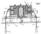
- stationary plates 1 are arranged as annular disks above a mounting surface for cone 2 at a distance from one another, so that chambers 3 are formed between the plates 1.
- a drivable central shaft 4 is arranged in the free core area of the plates 1, which carries pulleys 5 running in the direction of the plates 1, which extends into the area of the chambers 3 formed between the plates 1.
- a rope 6 connected to the cone 2 is arranged on each sheave 5, which is deflected via rollers 7 and 8 and is guided through bores 9 and 10 of a centering device 11.
- the ropes 6 are guided through the rope pulleys 5 arranged one above the other into the outer, upper area to rope tensioners 12.
- Each rope sheave 5 receives the associated rope 6 horizontally in a direction of rotation A, a tongue 13 springing when the rope is loaded being arranged in the peripheral region of the rope sheave 5. Furthermore, each rope sheave 5 has a nose 14 which increases the diameter, the rope 6 being arranged at the smaller diameter in the region of the nose 14 formed and the rope 6 being guided over the nose 14 during the winding-up process.
- the rope sheaves 5 are thus rotated in the direction A to set up the cones 2 and the cones 2 are pulled over the ropes 6 into the centering device 11. Subsequently, by rotating the rope sheaves 5 in direction B, the cones 2 are lowered for installation and the rope shovel 15 is formed on the plate 1 in order to enable an extraction process without hindrance.
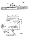
- the drive for adjusting the sheaves 5 via a central shaft 4 is formed according to FIG. 3 by a hydraulic cylinder 16 which is connected to the central shaft 4 via a cable transmission 17 and deflection rollers 18, 19. It is provided that the pulling-in process of the ropes 6 is associated with the extension movement of the hydraulic cylinder 16 and the large piston area is thus available.
- the central shaft 4 has a control edge 20, which is used on a control valve 21 for throttling the oil flow and is assigned to the cone 2 in accordance with the installation phase.
- the direction of movement for the hydraulic cylinder 16 is adjustable via a control valve 22.
- the cylinder annular space 24 formed by the piston rod can be connected to the cylinder piston space 25 of the hydraulic cylinder 16 via a pressure-dependent changeover valve 23 for the pulling-in of the cables 6, while the cylinder annular space 24 can be switched without pressure when the pressure in the cylinder piston space 25 increases. This allows the corresponding Speeds for the individual phases are better taken into account.
- a hydraulic accumulator 27 is arranged which, for example when the cones 2 are untangled, stores the energy and then releases it again with a loss of time, so that the cones 2 are pulled faster into the centering direction 11 when the untangling process is completed.
- the reservoir 27 is full, the pressure oil supply is then switched off via a limit switch 28.
- the drive can also be formed via another embodiment of a hydraulic cylinder 29, the piston rod 30 being designed as a toothed rack and an actuating movement being able to be initiated via an assigned gear wheel 31.
- a further embodiment according to FIGS. 6 and 7 for the drive is formed by a fixedly mounted motor 32 which drives a chain wheel 34 via a pendulum arm 33 and a control disk 35 serves to drive the central shaft with the rope pulleys 5.
- the control disk 35 carries a guideway in the form of a chain 36 which corresponds to the required rotary movements of the rope sheaves 5 and in which the chain wheel 34 engages with a slide 37 as a counter bearing.
- the motor 32 is only operated in one direction of rotation.
Landscapes
- Storing, Repeated Paying-Out, And Re-Storing Of Elongated Articles (AREA)
- Pulleys (AREA)
- Lift-Guide Devices, And Elevator Ropes And Cables (AREA)
- Transmission Devices (AREA)
- Unwinding Of Filamentary Materials (AREA)
Description
- Die Erfindung bezieht sich auf eine Vorrichtung zum automatischen Aufstellen von an Seilen befestigten Kegeln, die durch einen steuerbaren Antrieb über die durch Seilrollen umgelenkte Seile in zugeordnete Zentriervorrichtungen anhebbar und nach dem Absenken der Kegel auf eine Aufstellfläche absetzbar sind, wobei etwa parallel zur Aufstellfläche im Abstand übereinander angeordnete Seilkammern zur Ablage jeweils eines der Seile angeordnet sind und über eine Seiltrommel, an der die Seile befestigt sind, eine Aufwicklung der Seile zum Anheben und in der anderen Drehrichtung eine Absenken sowie Aufstellen der Kegel unter Bildung einer freien Seilschlaufe an jedem Seil erfolgt.
- Eine Vorrichtung dieser Art ist nach der DE-C-917174 bekannt. Hierbei hat sich herausgestellt, daß bei einer derartigen Aufstellvorrichtung das möglichst kraftlose Herausziehen eines Seilvorrates bei umgeworfenem Kegel nicht möglich ist. Durch die mitdrehende Seilkammer ist zwar, wie bei einer Winde, das Heben und Senken möglich, jedoch wird für das jeweilige Seil keine eindeutige Seilschlaufe gebildet. Dieses ist nicht durchführbar, da das Seil durch seine Reibkraft von der rückdrehenden Seilkammer unkontrolliert mitgenommen wird. Aus der sich ergebenden Seilverwirrung ist das einwandfreie und möglichst gleichmäßige Ausziehen des Seiles unter geringster Kraft, wie es beim Umfallen der Kegel vorschriftsmäßig erforderlich ist, nicht gewährleistet.
- Weiterhin ist entsprechend der DE-A 2300775 bekannt, Anordnungen mit einem horizontalen Direktzug der Seile anzuordnen oder die Seile einmal entsprechend dem Flaschenzugprinzip einzuscheren, um einen Horizontalzug zu ermöglichen. Die Antriebsarten lassen bei einer Antriebsgeschwindigkeit nur eine Grundgeschwindigkeit und eine Verzögerung beim Aufsetzen der Kegel durch mechanische Umlenkung zu. Weitere Nachteile bestehen in einer voluminösen Bauweise, und es entstehen relativ große Ausziehkräfte für die Seile beim Umfallen der Kegel.
- Die Aufgabe der Erfindung ist es, eine kompakte und stabile Ausbildung der gattungsgemäßen Art und einen ruhigen Lauf zu schaffen, die eine gute Funktionsfähigkeit mit einer leichten Zugänglichkeit der Seile mit einheitlicher Seilführung ermöglicht und geringe Ausziehkräfte der Seile durch umfallende Kegel gewährleistet.
- Die Lösung dieser Aufgabe erfolgt erfindungsgemäß dadurch, daß die Seilkammern durch ortsfeste im Abstand voneinander angeordnete Platten gebildet sind, wobei im Kernbereich zwischen den einzelnen Platten über den Antrieb drehbare Seilscheiben liegen, die zusammen die Seiltrommel bilden.
- Durch diese kompakte Ausbildung mit feststehenden Platten als Seilaufnahme ist eine große Laufruhe der Anordnung erzielbar und die Scheiben werden in dadurch gebildete Seilkammern auf den feststehenden Platten abgelegt, so daß beim Ausziehvorgang nur eine geringe Reibung aus dem Eigengewicht auftritt. Zusätzlich ist die Zuordnung des Antriebes entsprechend den Betriebserfordernissen problemlos. Da das Seil auf den feststehenden Platten nur abgelegt wird, ist es möglich, eine einwandfreie kontinuierlich verlaufende Seilschlaufe zu bilden.
- Eine einfache Ausbildung wird dadurch geschaffen, daß die Platten als Ringscheiben ausgebildet und die zugeordneten Seilscheiben über eine Zentralwelle mit einem Antrieb angeordnet sind.
- Um einen Ausgleich für unterschiedliche Seillängen bzw. Drehungen zu ermöglichen und die Justierung der einzelnen Seillängen zu vereinfachen, wird vorgeschlagen, daß jede Seilscheibe in ihrem Umfangsbereich zur Aufnahme des Seiles beim Aufwickelvorgang eine bei Seilbelastung einfedernde Zunge aufweist.
- Zur Unterstützung der Einstellung einer freien Seilschlaufe ist vorgesehen, daß jede Seilscheibe an ihrem Umfangsbereich eine den Durchmesser vergrößernde Nase aufweist, wobei das Seil im Bereich der Nase am kleinen Durchmesser angeordnet ist und beim Aufwickelvorgang das Seil über die Nase führbar ist.
- Zur Vereinfachung der Einstellbarkeit der Seillängen mit guter Zugänglichkeit wird vorgeschlagen, daß die Seile jeweils durch die Seilscheiben in den außenliegnden, oberen Bereich geführt und über einstellbare Seilspanner angeordnet sind.
- In der Zeichnung sind Ausführungsbeispiele der Erfindung schematisch dargestellt. Es zeigen:
- Fig. 1
- einen Halbschnitt einer Vorrichtung,
- Fig. 2
- einen Schnitt nach Linie II-II der Fig. 1,
- Fig. 3
- einen Antrieb über einen Hydraulikzylinder mit einer Seilübertragung,
- Fig. 4
- eine alternative Antriebsanordnung über einen Hydraulikzylinder mit einer Zahnradübertragung, wobei ein Zahnrad von der Kolbenstange als Zahnstange antreibbar ist,
- Fig. 5
- eine Schaltungsanordnung für einen Antrieb über einen Hydraulikzylinder,
- Fig. 6
- einen alternativen Antrieb über eine Steuerscheibe in Draufsicht gemäß Linie VI-VI der Fig. 7,
- Fig. 7
- eine Seitenansicht einer Ausbildung mit einer Steuerscheibe.
- Bei der dargestellten Anordnung sind ortsfeste Platten 1 als Ringscheiben oberhalb einer Aufstellfläche für Kegel 2 im Abstand zueinander angeordnet, so daß zwischen den Platten 1 Kammern 3 gebildet werden. Im freien Kernbereich der Platten 1 ist eine antreibbare Zentralwelle 4 angeordnet, die in Richtung der Platten 1 verlaufende Seilscheiben 5 trägt, die bis in den Bereich der zwischen den Platten 1 gebildeten Kammern 3 hineinreicht.
- An jeder Seilscheibe 5 ist ein mit dem Kegel 2 verbundenes Seil 6 angeordnet, das über Rollen 7 und 8 umgelenkt wird und durch Bohrungen 9 und 10 einer Zentriervorrichtung 11 geführt ist. Die Seile 6 sind dabei durch die übereinander angeordneten Seilscheiben 5 in den außenliegenden, oberen Bereich zu Seilspannern 12 geführt.
- Jede Seilscheibe 5 nimmt dabei das zugeordnete Seil 6 in einer Drehrichtung A horizontal auf, wobei eine bei Seilbelastung einfedernde Zunge 13 im Umfangsbereich der Seilscheibe 5 angeordnet ist. Ferner besitzt jede Seilscheibe 5 eine den Durchmesser vergrößernde Nase 14, wobei das Seil 6 im Bereich der gebildeten Nase 14 am kleineren Durchmesser angeordnet ist und beim Aufwickelvorgang das Seil 6 über die Nase 14 geführt wird.
- Hierdurch ist es möglich, bei der Rückdrehung der Seilscheibe 5 in der Richtung B nach dem Aufstellen der Kegel 2 eine freie Seilschlaufe 15 auf der Platte zu bilden.
- Die Seilscheiben 5 werden somit zum Aufstellen der Kegel 2 in Richtung A verdreht und dabei die Kegel 2 über die Seile 6 in die Zentriervorrichtung 11 gezogen. Anschließend erfolgt durch eine Drehbewegung der Seilscheiben 5 in Richtung B ein Absenken der Kegel 2 zur Aufstellung und die Bildung der Seilschaufe 15 auf der Platte 1, um einen Ausziehvorgang ohne Behinderung zu ermöglichen.
- Den Antrieb zur Verstellung der Seilscheiben 5 über eine Zentralwelle 4 wird gemäß Fig. 3 durch einen Hydraulikzylinder 16 gebildet, der über eine Seilübertragung 17 und Umlenkrollen 18, 19 mit der Zentralwelle 4 verbunden ist. Hierbei ist vorgesehen, daß dem Einziehvorgang der Seile 6 die Ausfahrbewegung des Hydraulikzylinders 16 zugeordnet ist und somit die große Kolbenfläche zur Verfügung steht. Zusätzlich weist die Zentralwelle 4 eine Steuerkante 20 kauf, die auf ein Steuerventil 21 zur Drosselung des Ölstroms dient und entsprechend der Aufstellphase der Kegel 2 zugeordnet ist.
- In dem gezeigten Schaltungsschema gemäß Fig. 5 ist die Bewegungsrichtung für den Hydraulikzylinder 16 über ein Steuerventil 22 einstellbar. Zusätzlich ist über ein druckabhängiges Umschaltventil 23 für den Einziehvorgang der Seile 6 der durch die Kolbestange gebildete Zylinderringraum 24 mit dem Zylinderkolbenraum 25 des Hydraulikzylinders 16 verbindbar, während bei Druckanstieg im Zylinderkolbenraum 25 der Zylinderringraum 24 drucklos schaltbar ist. Hierdurch kann den entsprechenden Geschwindigkeiten für die einzelnen Phasen besser Rechnung getragen werden.
- Weiterhin ist ein hydraulischer Speicher 27 angeordnet, der beispielsweise beim Entwirren der Kegel 2 mit einem auftretenden Zeitverlust, die Energie speichert und anschließend wieder abgibt, so daß die Kegel 2 bei Beendigung des Entwirrprozesses schneller in die Zentrierrichtung 11 gezogen werden. Bei aufgefülltem Speicher 27 wird dann über einen Endschalter 28 die Druckölversorgung abgeschaltet.
- Selbstverständlich kann der Antrieb auch über eine andere Ausführung eines Hydraulikzylinders 29 gebildet werden, wobei die Kolbenstange 30 als Zahnstange ausgebildet ist und über ein zugeordnetes Zahnrad 31 eine Stellbewegung einleitbar ist.
- Eine weitere Ausführungsform gemäß Fig. 6 und 7 für den Antrieb wird durch einen ortsfest gelagerten Motor 32 gebildet, der über einen Pendelarm 33 ein Kettenrad 34 antreibt und eine Steuerscheibe 35 zum Antrieb der Zentralwelle mit den Seilscheiben 5 dient. Hierbei trägt die Steuerscheibe 35 eine für die erforderlichen Drehbewegungen der Seilscheiben 5 entsprechende Führungsbahn in Form einer Kette 36, in die das Kettenrad 34 mit einem Gleitstück 37 als Gegenlager eingreift. Der Motor 32 wird dabei nur in einer Drehrichtung betrieben.
Claims (5)
Priority Applications (4)
| Application Number | Priority Date | Filing Date | Title |
|---|---|---|---|
| DE19863637909 DE3637909A1 (de) | 1986-11-06 | 1986-11-06 | Vorrichtung zum automatischen aufstellen von an seilen befestigten kegeln |
| AT88107682T ATE65927T1 (de) | 1988-05-13 | 1988-05-13 | Vorrichtung zum automatischen aufstellen von an seilen befestigten kegeln. |
| DE8888107682T DE3864141D1 (de) | 1988-05-13 | 1988-05-13 | Vorrichtung zum automatischen aufstellen von an seilen befestigten kegeln. |
| EP88107682A EP0341333B1 (de) | 1988-05-13 | 1988-05-13 | Vorrichtung zum automatischen Aufstellen von an Seilen befestigten Kegeln |
Applications Claiming Priority (1)
| Application Number | Priority Date | Filing Date | Title |
|---|---|---|---|
| EP88107682A EP0341333B1 (de) | 1988-05-13 | 1988-05-13 | Vorrichtung zum automatischen Aufstellen von an Seilen befestigten Kegeln |
Publications (2)
| Publication Number | Publication Date |
|---|---|
| EP0341333A1 EP0341333A1 (de) | 1989-11-15 |
| EP0341333B1 true EP0341333B1 (de) | 1991-08-07 |
Family
ID=8198970
Family Applications (1)
| Application Number | Title | Priority Date | Filing Date |
|---|---|---|---|
| EP88107682A Expired - Lifetime EP0341333B1 (de) | 1986-11-06 | 1988-05-13 | Vorrichtung zum automatischen Aufstellen von an Seilen befestigten Kegeln |
Country Status (3)
| Country | Link |
|---|---|
| EP (1) | EP0341333B1 (de) |
| AT (1) | ATE65927T1 (de) |
| DE (2) | DE3637909A1 (de) |
Families Citing this family (1)
| Publication number | Priority date | Publication date | Assignee | Title |
|---|---|---|---|---|
| DE3637909A1 (de) * | 1986-11-06 | 1988-05-19 | Dieter Blum | Vorrichtung zum automatischen aufstellen von an seilen befestigten kegeln |
Family Cites Families (5)
| Publication number | Priority date | Publication date | Assignee | Title |
|---|---|---|---|---|
| US2566987A (en) * | 1946-02-19 | 1951-09-04 | Humber Gustave | Means for resetting bowling pins |
| CH283800A (de) * | 1950-04-05 | 1952-06-30 | Rihm Wernli August | Motorisch angetriebene Kegelaufstell- und Kugelrückgabeeinrichtung bei Kegelbahnen. |
| DE917174C (de) * | 1952-01-12 | 1955-03-10 | Adolf Suter | Kegelaufstellvorrichtung |
| DE2300775A1 (de) * | 1973-01-08 | 1974-07-11 | Rodrigo Dipl Ing Michalowsky | Kegelstellmaschine |
| DE3637909A1 (de) * | 1986-11-06 | 1988-05-19 | Dieter Blum | Vorrichtung zum automatischen aufstellen von an seilen befestigten kegeln |
-
1986
- 1986-11-06 DE DE19863637909 patent/DE3637909A1/de active Granted
-
1988
- 1988-05-13 EP EP88107682A patent/EP0341333B1/de not_active Expired - Lifetime
- 1988-05-13 AT AT88107682T patent/ATE65927T1/de not_active IP Right Cessation
- 1988-05-13 DE DE8888107682T patent/DE3864141D1/de not_active Expired - Lifetime
Also Published As
| Publication number | Publication date |
|---|---|
| EP0341333A1 (de) | 1989-11-15 |
| DE3864141D1 (de) | 1991-09-12 |
| ATE65927T1 (de) | 1991-08-15 |
| DE3637909A1 (de) | 1988-05-19 |
Similar Documents
| Publication | Publication Date | Title |
|---|---|---|
| EP0341333B1 (de) | Vorrichtung zum automatischen Aufstellen von an Seilen befestigten Kegeln | |
| DE4206630A1 (de) | Turmkran | |
| DE2404897C3 (de) | Saugbagger mit mittels Seilzug am Schiffskörper aufgehängtem Saugkopf | |
| DE2803895C2 (de) | Gießereikran | |
| DE1210155B (de) | Motorisch angetriebene Greiferwinde | |
| DE3015366A1 (de) | Verlitzmaschine mit halbautomatischer spulenwechselvorrichtung | |
| DE891730C (de) | Wippkran | |
| DE2410807A1 (de) | Kran mit einer kombinierten vorrichtung zum verhindern von schlappseil und der unterschreitung einer vorgebbaren mindesthubseilkraft | |
| CH540191A (de) | Ausleger-Hängekran für landwirtschaftliche Gebäude | |
| DE3245511A1 (de) | Kran, insbesondere turmdrehkran | |
| DE1017082B (de) | Spannvorrichtung fuer ein Foerderband | |
| DE1135148B (de) | Einrichtung zum selbsttaetigen Steuern von Kranantrieben od. dgl. | |
| AT314143B (de) | Hubwerk für Hebezeuge | |
| DE1067984B (de) | ||
| DE19857253A1 (de) | Einkristall-Hebevorrichtung | |
| DE2127066A1 (en) | Nuclear fuel - rod handling gear - using toothed tracks and guide pinion (in guide tube) | |
| DE257294C (de) | ||
| DE942348C (de) | Auslegerkran | |
| DE727589C (de) | Vorrichtung zur Verhinderung von Schlappseibildung im Hubseil von Hebezeugen | |
| DE216077C (de) | ||
| DE1048305B (de) | Wickeltrommel, deren Bremswirkung durch das Trommelgewicht geregelt wird, insbesondere für strangförmiges Wickelgut für elektrische Kabel | |
| AT46476B (de) | Hebe- und Transportvorrichtung. | |
| AT233769B (de) | Laufkatze | |
| DE1179682B (de) | Turmdrehkran mit Laufkatzenausleger | |
| DE3937080A1 (de) | Hubseil-stuetzvorrichtung fuer einen auslegerkran |
Legal Events
| Date | Code | Title | Description |
|---|---|---|---|
| PUAI | Public reference made under article 153(3) epc to a published international application that has entered the european phase |
Free format text: ORIGINAL CODE: 0009012 |
|
| 17P | Request for examination filed |
Effective date: 19890607 |
|
| AK | Designated contracting states |
Kind code of ref document: A1 Designated state(s): AT BE CH DE FR GB IT LI LU NL |
|
| 17Q | First examination report despatched |
Effective date: 19900706 |
|
| GRAA | (expected) grant |
Free format text: ORIGINAL CODE: 0009210 |
|
| AK | Designated contracting states |
Kind code of ref document: B1 Designated state(s): AT BE CH DE FR GB IT LI LU NL |
|
| REF | Corresponds to: |
Ref document number: 65927 Country of ref document: AT Date of ref document: 19910815 Kind code of ref document: T |
|
| REF | Corresponds to: |
Ref document number: 3864141 Country of ref document: DE Date of ref document: 19910912 |
|
| ITF | It: translation for a ep patent filed | ||
| ET | Fr: translation filed | ||
| GBT | Gb: translation of ep patent filed (gb section 77(6)(a)/1977) | ||
| PLBE | No opposition filed within time limit |
Free format text: ORIGINAL CODE: 0009261 |
|
| STAA | Information on the status of an ep patent application or granted ep patent |
Free format text: STATUS: NO OPPOSITION FILED WITHIN TIME LIMIT |
|
| 26N | No opposition filed | ||
| PGFP | Annual fee paid to national office [announced via postgrant information from national office to epo] |
Ref country code: LU Payment date: 19930527 Year of fee payment: 6 |
|
| PGFP | Annual fee paid to national office [announced via postgrant information from national office to epo] |
Ref country code: NL Payment date: 19930531 Year of fee payment: 6 |
|
| PGFP | Annual fee paid to national office [announced via postgrant information from national office to epo] |
Ref country code: BE Payment date: 19930702 Year of fee payment: 6 |
|
| EPTA | Lu: last paid annual fee | ||
| PG25 | Lapsed in a contracting state [announced via postgrant information from national office to epo] |
Ref country code: LU Free format text: LAPSE BECAUSE OF NON-PAYMENT OF DUE FEES Effective date: 19940513 |
|
| PG25 | Lapsed in a contracting state [announced via postgrant information from national office to epo] |
Ref country code: BE Effective date: 19940531 |
|
| PGFP | Annual fee paid to national office [announced via postgrant information from national office to epo] |
Ref country code: GB Payment date: 19940602 Year of fee payment: 7 |
|
| PGFP | Annual fee paid to national office [announced via postgrant information from national office to epo] |
Ref country code: DE Payment date: 19940613 Year of fee payment: 7 |
|
| PGFP | Annual fee paid to national office [announced via postgrant information from national office to epo] |
Ref country code: AT Payment date: 19940615 Year of fee payment: 7 |
|
| PGFP | Annual fee paid to national office [announced via postgrant information from national office to epo] |
Ref country code: FR Payment date: 19940621 Year of fee payment: 7 Ref country code: CH Payment date: 19940621 Year of fee payment: 7 |
|
| BERE | Be: lapsed |
Owner name: BLUM DIETER Effective date: 19940531 |
|
| PG25 | Lapsed in a contracting state [announced via postgrant information from national office to epo] |
Ref country code: NL Effective date: 19941201 |
|
| NLV4 | Nl: lapsed or anulled due to non-payment of the annual fee | ||
| PG25 | Lapsed in a contracting state [announced via postgrant information from national office to epo] |
Ref country code: GB Effective date: 19950513 Ref country code: AT Effective date: 19950513 |
|
| PG25 | Lapsed in a contracting state [announced via postgrant information from national office to epo] |
Ref country code: LI Effective date: 19950531 Ref country code: CH Effective date: 19950531 |
|
| GBPC | Gb: european patent ceased through non-payment of renewal fee |
Effective date: 19950513 |
|
| REG | Reference to a national code |
Ref country code: CH Ref legal event code: PL |
|
| PG25 | Lapsed in a contracting state [announced via postgrant information from national office to epo] |
Ref country code: DE Effective date: 19960201 |
|
| PG25 | Lapsed in a contracting state [announced via postgrant information from national office to epo] |
Ref country code: FR Effective date: 19960229 |
|
| REG | Reference to a national code |
Ref country code: FR Ref legal event code: ST |
|
| REG | Reference to a national code |
Ref country code: FR Ref legal event code: ST |
|
| PG25 | Lapsed in a contracting state [announced via postgrant information from national office to epo] |
Ref country code: IT Free format text: LAPSE BECAUSE OF NON-PAYMENT OF DUE FEES;WARNING: LAPSES OF ITALIAN PATENTS WITH EFFECTIVE DATE BEFORE 2007 MAY HAVE OCCURRED AT ANY TIME BEFORE 2007. THE CORRECT EFFECTIVE DATE MAY BE DIFFERENT FROM THE ONE RECORDED. Effective date: 20050513 |