EP0341333B1 - Dispositif pour replacer automatiquement les quilles fixées à des cordes - Google Patents
Dispositif pour replacer automatiquement les quilles fixées à des cordes Download PDFInfo
- Publication number
- EP0341333B1 EP0341333B1 EP88107682A EP88107682A EP0341333B1 EP 0341333 B1 EP0341333 B1 EP 0341333B1 EP 88107682 A EP88107682 A EP 88107682A EP 88107682 A EP88107682 A EP 88107682A EP 0341333 B1 EP0341333 B1 EP 0341333B1
- Authority
- EP
- European Patent Office
- Prior art keywords
- rope
- ropes
- drive
- plates
- region
- Prior art date
- Legal status (The legal status is an assumption and is not a legal conclusion. Google has not performed a legal analysis and makes no representation as to the accuracy of the status listed.)
- Expired - Lifetime
Links
Images


Classifications
-
- A—HUMAN NECESSITIES
- A63—SPORTS; GAMES; AMUSEMENTS
- A63D—BOWLING GAMES, e.g. SKITTLES, BOCCE OR BOWLS; INSTALLATIONS THEREFOR; BAGATELLE OR SIMILAR GAMES; BILLIARDS
- A63D5/00—Accessories for bowling-alleys or table alleys
- A63D5/08—Arrangements for setting-up or taking away pins
-
- A—HUMAN NECESSITIES
- A63—SPORTS; GAMES; AMUSEMENTS
- A63D—BOWLING GAMES, e.g. SKITTLES, BOCCE OR BOWLS; INSTALLATIONS THEREFOR; BAGATELLE OR SIMILAR GAMES; BILLIARDS
- A63D5/00—Accessories for bowling-alleys or table alleys
- A63D5/08—Arrangements for setting-up or taking away pins
- A63D2005/083—Threaded pins
Definitions
- the invention relates to a device for automatically setting up cones attached to ropes, which can be raised by a controllable drive via the ropes deflected by rope pulleys into assigned centering devices and, after the cones have been lowered, can be placed on an installation surface, approximately parallel to the installation surface at a distance Rope chambers arranged one above the other for the storage of one of the ropes and a rope drum to which the ropes are attached, the ropes are wound up for lifting and in the other direction of rotation the cones are lowered and the cones are set up to form a free rope loop on each rope.
- a device of this type is known from DE-C-917174. It has been found that with such a set-up device it is not possible to pull out a rope supply with as little force as possible when the cone is knocked over. Due to the rotating cable chamber, as with a winch, lifting and lowering is possible, but no clear cable loop is formed for the respective cable. This is not feasible because the rope is dragged uncontrollably by the rotating rope chamber due to its frictional force. The resulting rope confusion does not guarantee that the rope can be pulled out smoothly and as evenly as possible under the slightest force, as required by law when the cone falls over.
- the object of the invention is to provide a compact and stable design of the generic type and a quiet run, which enables good functionality with easy access to the ropes with uniform rope guidance and ensures low pulling forces of the ropes by falling cones.
- the cable chambers are formed by stationary plates which are arranged at a distance from one another, and in the core area between the individual plates there are rotatable cable pulleys via the drive, which together form the cable drum.
- a simple design is created in that the plates are designed as ring disks and the associated rope disks are arranged with a drive via a central shaft.
- each rope sheave have a tongue that deflects when the rope is loaded during the winding process in its peripheral region.
- each rope sheave has a diameter-enlarging nose on its circumferential area, the rope being arranged in the area of the nose at the small diameter and the rope being able to be guided over the nose during the winding-up process.
- the ropes are each guided through the rope sheaves into the outer, upper area and are arranged via adjustable rope tensioners.
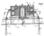
- stationary plates 1 are arranged as annular disks above a mounting surface for cone 2 at a distance from one another, so that chambers 3 are formed between the plates 1.
- a drivable central shaft 4 is arranged in the free core area of the plates 1, which carries pulleys 5 running in the direction of the plates 1, which extends into the area of the chambers 3 formed between the plates 1.
- a rope 6 connected to the cone 2 is arranged on each sheave 5, which is deflected via rollers 7 and 8 and is guided through bores 9 and 10 of a centering device 11.
- the ropes 6 are guided through the rope pulleys 5 arranged one above the other into the outer, upper area to rope tensioners 12.
- Each rope sheave 5 receives the associated rope 6 horizontally in a direction of rotation A, a tongue 13 springing when the rope is loaded being arranged in the peripheral region of the rope sheave 5. Furthermore, each rope sheave 5 has a nose 14 which increases the diameter, the rope 6 being arranged at the smaller diameter in the region of the nose 14 formed and the rope 6 being guided over the nose 14 during the winding-up process.
- the rope sheaves 5 are thus rotated in the direction A to set up the cones 2 and the cones 2 are pulled over the ropes 6 into the centering device 11. Subsequently, by rotating the rope sheaves 5 in direction B, the cones 2 are lowered for installation and the rope shovel 15 is formed on the plate 1 in order to enable an extraction process without hindrance.
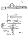
- the drive for adjusting the sheaves 5 via a central shaft 4 is formed according to FIG. 3 by a hydraulic cylinder 16 which is connected to the central shaft 4 via a cable transmission 17 and deflection rollers 18, 19. It is provided that the pulling-in process of the ropes 6 is associated with the extension movement of the hydraulic cylinder 16 and the large piston area is thus available.
- the central shaft 4 has a control edge 20, which is used on a control valve 21 for throttling the oil flow and is assigned to the cone 2 in accordance with the installation phase.
- the direction of movement for the hydraulic cylinder 16 is adjustable via a control valve 22.
- the cylinder annular space 24 formed by the piston rod can be connected to the cylinder piston space 25 of the hydraulic cylinder 16 via a pressure-dependent changeover valve 23 for the pulling-in of the cables 6, while the cylinder annular space 24 can be switched without pressure when the pressure in the cylinder piston space 25 increases. This allows the corresponding Speeds for the individual phases are better taken into account.
- a hydraulic accumulator 27 is arranged which, for example when the cones 2 are untangled, stores the energy and then releases it again with a loss of time, so that the cones 2 are pulled faster into the centering direction 11 when the untangling process is completed.
- the reservoir 27 is full, the pressure oil supply is then switched off via a limit switch 28.
- the drive can also be formed via another embodiment of a hydraulic cylinder 29, the piston rod 30 being designed as a toothed rack and an actuating movement being able to be initiated via an assigned gear wheel 31.
- a further embodiment according to FIGS. 6 and 7 for the drive is formed by a fixedly mounted motor 32 which drives a chain wheel 34 via a pendulum arm 33 and a control disk 35 serves to drive the central shaft with the rope pulleys 5.
- the control disk 35 carries a guideway in the form of a chain 36 which corresponds to the required rotary movements of the rope sheaves 5 and in which the chain wheel 34 engages with a slide 37 as a counter bearing.
- the motor 32 is only operated in one direction of rotation.
Landscapes
- Lift-Guide Devices, And Elevator Ropes And Cables (AREA)
- Unwinding Of Filamentary Materials (AREA)
- Transmission Devices (AREA)
- Pulleys (AREA)
- Storing, Repeated Paying-Out, And Re-Storing Of Elongated Articles (AREA)
Claims (5)
Priority Applications (4)
| Application Number | Priority Date | Filing Date | Title |
|---|---|---|---|
| DE19863637909 DE3637909A1 (de) | 1986-11-06 | 1986-11-06 | Vorrichtung zum automatischen aufstellen von an seilen befestigten kegeln |
| EP88107682A EP0341333B1 (fr) | 1988-05-13 | 1988-05-13 | Dispositif pour replacer automatiquement les quilles fixées à des cordes |
| AT88107682T ATE65927T1 (de) | 1988-05-13 | 1988-05-13 | Vorrichtung zum automatischen aufstellen von an seilen befestigten kegeln. |
| DE8888107682T DE3864141D1 (de) | 1988-05-13 | 1988-05-13 | Vorrichtung zum automatischen aufstellen von an seilen befestigten kegeln. |
Applications Claiming Priority (1)
| Application Number | Priority Date | Filing Date | Title |
|---|---|---|---|
| EP88107682A EP0341333B1 (fr) | 1988-05-13 | 1988-05-13 | Dispositif pour replacer automatiquement les quilles fixées à des cordes |
Publications (2)
| Publication Number | Publication Date |
|---|---|
| EP0341333A1 EP0341333A1 (fr) | 1989-11-15 |
| EP0341333B1 true EP0341333B1 (fr) | 1991-08-07 |
Family
ID=8198970
Family Applications (1)
| Application Number | Title | Priority Date | Filing Date |
|---|---|---|---|
| EP88107682A Expired - Lifetime EP0341333B1 (fr) | 1986-11-06 | 1988-05-13 | Dispositif pour replacer automatiquement les quilles fixées à des cordes |
Country Status (3)
| Country | Link |
|---|---|
| EP (1) | EP0341333B1 (fr) |
| AT (1) | ATE65927T1 (fr) |
| DE (2) | DE3637909A1 (fr) |
Families Citing this family (1)
| Publication number | Priority date | Publication date | Assignee | Title |
|---|---|---|---|---|
| DE3637909A1 (de) * | 1986-11-06 | 1988-05-19 | Dieter Blum | Vorrichtung zum automatischen aufstellen von an seilen befestigten kegeln |
Family Cites Families (5)
| Publication number | Priority date | Publication date | Assignee | Title |
|---|---|---|---|---|
| US2566987A (en) * | 1946-02-19 | 1951-09-04 | Humber Gustave | Means for resetting bowling pins |
| CH283800A (de) * | 1950-04-05 | 1952-06-30 | Rihm Wernli August | Motorisch angetriebene Kegelaufstell- und Kugelrückgabeeinrichtung bei Kegelbahnen. |
| DE917174C (de) * | 1952-01-12 | 1955-03-10 | Adolf Suter | Kegelaufstellvorrichtung |
| DE2300775A1 (de) * | 1973-01-08 | 1974-07-11 | Rodrigo Dipl Ing Michalowsky | Kegelstellmaschine |
| DE3637909A1 (de) * | 1986-11-06 | 1988-05-19 | Dieter Blum | Vorrichtung zum automatischen aufstellen von an seilen befestigten kegeln |
-
1986
- 1986-11-06 DE DE19863637909 patent/DE3637909A1/de active Granted
-
1988
- 1988-05-13 EP EP88107682A patent/EP0341333B1/fr not_active Expired - Lifetime
- 1988-05-13 AT AT88107682T patent/ATE65927T1/de not_active IP Right Cessation
- 1988-05-13 DE DE8888107682T patent/DE3864141D1/de not_active Expired - Lifetime
Also Published As
| Publication number | Publication date |
|---|---|
| EP0341333A1 (fr) | 1989-11-15 |
| DE3637909A1 (de) | 1988-05-19 |
| DE3864141D1 (de) | 1991-09-12 |
| ATE65927T1 (de) | 1991-08-15 |
Similar Documents
| Publication | Publication Date | Title |
|---|---|---|
| CH383584A (de) | Laufkatze für Laufkran | |
| DE1809730A1 (de) | Rotierender Ring fuer Spinn- oder Zwirnmaschinen | |
| EP0341333B1 (fr) | Dispositif pour replacer automatiquement les quilles fixées à des cordes | |
| DE4206630A1 (de) | Turmkran | |
| DE2404897C3 (de) | Saugbagger mit mittels Seilzug am Schiffskörper aufgehängtem Saugkopf | |
| DE2803895C2 (de) | Gießereikran | |
| DE1210155B (de) | Motorisch angetriebene Greiferwinde | |
| DE3015366A1 (de) | Verlitzmaschine mit halbautomatischer spulenwechselvorrichtung | |
| DE891730C (de) | Wippkran | |
| DE2410807A1 (de) | Kran mit einer kombinierten vorrichtung zum verhindern von schlappseil und der unterschreitung einer vorgebbaren mindesthubseilkraft | |
| CH540191A (de) | Ausleger-Hängekran für landwirtschaftliche Gebäude | |
| DE3245511A1 (de) | Kran, insbesondere turmdrehkran | |
| DE1135148B (de) | Einrichtung zum selbsttaetigen Steuern von Kranantrieben od. dgl. | |
| AT314143B (de) | Hubwerk für Hebezeuge | |
| DE1067984B (fr) | ||
| DE19857253A1 (de) | Einkristall-Hebevorrichtung | |
| DE2127066A1 (en) | Nuclear fuel - rod handling gear - using toothed tracks and guide pinion (in guide tube) | |
| DE257294C (fr) | ||
| DE942348C (de) | Auslegerkran | |
| DE727589C (de) | Vorrichtung zur Verhinderung von Schlappseibildung im Hubseil von Hebezeugen | |
| DE216077C (fr) | ||
| AT46476B (de) | Hebe- und Transportvorrichtung. | |
| AT233769B (de) | Laufkatze | |
| DE1179682B (de) | Turmdrehkran mit Laufkatzenausleger | |
| DE3937080A1 (de) | Hubseil-stuetzvorrichtung fuer einen auslegerkran |
Legal Events
| Date | Code | Title | Description |
|---|---|---|---|
| PUAI | Public reference made under article 153(3) epc to a published international application that has entered the european phase |
Free format text: ORIGINAL CODE: 0009012 |
|
| 17P | Request for examination filed |
Effective date: 19890607 |
|
| AK | Designated contracting states |
Kind code of ref document: A1 Designated state(s): AT BE CH DE FR GB IT LI LU NL |
|
| 17Q | First examination report despatched |
Effective date: 19900706 |
|
| GRAA | (expected) grant |
Free format text: ORIGINAL CODE: 0009210 |
|
| AK | Designated contracting states |
Kind code of ref document: B1 Designated state(s): AT BE CH DE FR GB IT LI LU NL |
|
| REF | Corresponds to: |
Ref document number: 65927 Country of ref document: AT Date of ref document: 19910815 Kind code of ref document: T |
|
| REF | Corresponds to: |
Ref document number: 3864141 Country of ref document: DE Date of ref document: 19910912 |
|
| ITF | It: translation for a ep patent filed | ||
| ET | Fr: translation filed | ||
| GBT | Gb: translation of ep patent filed (gb section 77(6)(a)/1977) | ||
| PLBE | No opposition filed within time limit |
Free format text: ORIGINAL CODE: 0009261 |
|
| STAA | Information on the status of an ep patent application or granted ep patent |
Free format text: STATUS: NO OPPOSITION FILED WITHIN TIME LIMIT |
|
| 26N | No opposition filed | ||
| PGFP | Annual fee paid to national office [announced via postgrant information from national office to epo] |
Ref country code: LU Payment date: 19930527 Year of fee payment: 6 |
|
| PGFP | Annual fee paid to national office [announced via postgrant information from national office to epo] |
Ref country code: NL Payment date: 19930531 Year of fee payment: 6 |
|
| PGFP | Annual fee paid to national office [announced via postgrant information from national office to epo] |
Ref country code: BE Payment date: 19930702 Year of fee payment: 6 |
|
| EPTA | Lu: last paid annual fee | ||
| PG25 | Lapsed in a contracting state [announced via postgrant information from national office to epo] |
Ref country code: LU Free format text: LAPSE BECAUSE OF NON-PAYMENT OF DUE FEES Effective date: 19940513 |
|
| PG25 | Lapsed in a contracting state [announced via postgrant information from national office to epo] |
Ref country code: BE Effective date: 19940531 |
|
| PGFP | Annual fee paid to national office [announced via postgrant information from national office to epo] |
Ref country code: GB Payment date: 19940602 Year of fee payment: 7 |
|
| PGFP | Annual fee paid to national office [announced via postgrant information from national office to epo] |
Ref country code: DE Payment date: 19940613 Year of fee payment: 7 |
|
| PGFP | Annual fee paid to national office [announced via postgrant information from national office to epo] |
Ref country code: AT Payment date: 19940615 Year of fee payment: 7 |
|
| PGFP | Annual fee paid to national office [announced via postgrant information from national office to epo] |
Ref country code: FR Payment date: 19940621 Year of fee payment: 7 Ref country code: CH Payment date: 19940621 Year of fee payment: 7 |
|
| BERE | Be: lapsed |
Owner name: BLUM DIETER Effective date: 19940531 |
|
| PG25 | Lapsed in a contracting state [announced via postgrant information from national office to epo] |
Ref country code: NL Effective date: 19941201 |
|
| NLV4 | Nl: lapsed or anulled due to non-payment of the annual fee | ||
| PG25 | Lapsed in a contracting state [announced via postgrant information from national office to epo] |
Ref country code: GB Effective date: 19950513 Ref country code: AT Effective date: 19950513 |
|
| PG25 | Lapsed in a contracting state [announced via postgrant information from national office to epo] |
Ref country code: LI Effective date: 19950531 Ref country code: CH Effective date: 19950531 |
|
| GBPC | Gb: european patent ceased through non-payment of renewal fee |
Effective date: 19950513 |
|
| REG | Reference to a national code |
Ref country code: CH Ref legal event code: PL |
|
| PG25 | Lapsed in a contracting state [announced via postgrant information from national office to epo] |
Ref country code: DE Effective date: 19960201 |
|
| PG25 | Lapsed in a contracting state [announced via postgrant information from national office to epo] |
Ref country code: FR Effective date: 19960229 |
|
| REG | Reference to a national code |
Ref country code: FR Ref legal event code: ST |
|
| REG | Reference to a national code |
Ref country code: FR Ref legal event code: ST |
|
| PG25 | Lapsed in a contracting state [announced via postgrant information from national office to epo] |
Ref country code: IT Free format text: LAPSE BECAUSE OF NON-PAYMENT OF DUE FEES;WARNING: LAPSES OF ITALIAN PATENTS WITH EFFECTIVE DATE BEFORE 2007 MAY HAVE OCCURRED AT ANY TIME BEFORE 2007. THE CORRECT EFFECTIVE DATE MAY BE DIFFERENT FROM THE ONE RECORDED. Effective date: 20050513 |