EP0340602B1 - Antrieb für einen Maschinenschraubstock - Google Patents
Antrieb für einen Maschinenschraubstock Download PDFInfo
- Publication number
- EP0340602B1 EP0340602B1 EP89107420A EP89107420A EP0340602B1 EP 0340602 B1 EP0340602 B1 EP 0340602B1 EP 89107420 A EP89107420 A EP 89107420A EP 89107420 A EP89107420 A EP 89107420A EP 0340602 B1 EP0340602 B1 EP 0340602B1
- Authority
- EP
- European Patent Office
- Prior art keywords
- drive
- sleeve
- chamber
- power amplifier
- drive according
- Prior art date
- Legal status (The legal status is an assumption and is not a legal conclusion. Google has not performed a legal analysis and makes no representation as to the accuracy of the status listed.)
- Expired - Lifetime
Links
Images

Classifications
-
- B—PERFORMING OPERATIONS; TRANSPORTING
- B25—HAND TOOLS; PORTABLE POWER-DRIVEN TOOLS; MANIPULATORS
- B25B—TOOLS OR BENCH DEVICES NOT OTHERWISE PROVIDED FOR, FOR FASTENING, CONNECTING, DISENGAGING OR HOLDING
- B25B1/00—Vices
-
- B—PERFORMING OPERATIONS; TRANSPORTING
- B25—HAND TOOLS; PORTABLE POWER-DRIVEN TOOLS; MANIPULATORS
- B25B—TOOLS OR BENCH DEVICES NOT OTHERWISE PROVIDED FOR, FOR FASTENING, CONNECTING, DISENGAGING OR HOLDING
- B25B1/00—Vices
- B25B1/24—Details, e.g. jaws of special shape, slideways
- B25B1/2405—Construction of the jaws
- B25B1/2473—Construction of the jaws with pull-down action on the workpiece
-
- B—PERFORMING OPERATIONS; TRANSPORTING
- B25—HAND TOOLS; PORTABLE POWER-DRIVEN TOOLS; MANIPULATORS
- B25B—TOOLS OR BENCH DEVICES NOT OTHERWISE PROVIDED FOR, FOR FASTENING, CONNECTING, DISENGAGING OR HOLDING
- B25B1/00—Vices
- B25B1/06—Arrangements for positively actuating jaws
- B25B1/10—Arrangements for positively actuating jaws using screws
- B25B1/106—Arrangements for positively actuating jaws using screws with mechanical or hydraulic power amplifiers
Definitions
- a machine vice of the type specified is described.
- a fixed jaw is arranged on a vice body at one end and a movable jaw at the other end.
- the drive consists of a power amplifier that acts on a screw spindle.
- the arrangement is such that the crank is located on one side of the abutment at one end of the vice body and acts on the power amplifier on the other side of the abutment.
- the movable jaw is first pushed forward via the screw spindle and the workpiece is clamped with a predetermined force. If this force or the torque applied to the crank is exceeded, a clutch disengages.
- a power amplifier as used in the machine vice mentioned above, has become known, for example, from DE-PS 23 08 175.
- the object is achieved in a simple manner by the invention.
- the vice body, the slide and the jaws remain completely unchanged.
- the abutment can also be used.
- DE-AS 12 88 523 describes a machine vice in which the screw spindle is arranged inside the movable jaw.
- the abutment is also housed inside the movable jaw, and the entire drive is above the clamping level.
- a power amplifier is provided outside the movable jaw, the power amplifier then acting on the movable jaw via the screw spindle.
- the screw spindle is located essentially on one side of the support surface and the booster is on the other side of the support surface, that a sleeve is provided which carries the support surface on an annular flange and whose bore penetrates an extension of the screw spindle that the booster acts on the extension, and that the booster can be connected to the sleeve, so that the booster is supported on the abutment via the support surface. days.
- One part with the screw spindle is to be inserted into the abutment from one side, and the other part of the drive is connected to the first part from the other side, that is to say from the rear of the abutment.
- the screw spindle can interact with the sleeve in various ways. It is expedient if the screw spindle can be rotated with the sleeve, but is axially movable within the limits of the sleeve under the action of the power amplifier. In itself, a non-rotatable sleeve would also be useful. However, the construction proposed above is preferred. As is known per se, a suitable roller bearing, for example a needle bearing, can be used to reduce the friction between the sleeve and the abutment.
- a rotatable chamber is provided for the power amplifier.
- the screw spindle extension projects into this chamber on the abutment side, while the crankshaft projects into the chamber on the crank side.
- an internal thread is provided in the chamber in which the crankshaft is supported.
- a disengageable clutch is provided in the chamber, the clutch limiting the torque applied by the crank to be transmitted to the chamber, as is known per se. This ensures that when the movable jaw moves, the screw spindle is rotated first, and that the clutch then disengages at certain clamping forces and the crankshaft acts on the power amplifier.
- the chamber preferably consists of two parts screwed together, one part receiving the thread for the crankshaft and the clutch, while the other part is screwed to the sleeve.
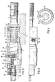
- the jaw 9 is fixedly arranged on the vice body 8 at one end.
- the abutment 6 is provided, which receives the drive 28 according to the invention.
- Carriage 29, which carries movable jaw 4, is mounted in vice body 8.
- the feed movement for the slide 29 takes place by means of the screw spindle 1. This engages with the screw thread 30 in the spindle nut 10, which extends over the entire length of the spindle.
- Fig. 1 shows that position of the machine vice 5, in which the jaw 4 is fully retracted.
- the feed movement is initiated into the drive via the crank 3, which can be plugged onto the polygon 31.
- the sleeve 11 is supported on the abutment 6 with the support surface 40 of the ring flange 7.
- a gradation 34 is provided for transmitting the pressures of the screw spindle 1 to the sleeve 11.
- the parts 19 and 20 together form the chamber 15 which receives the power amplifier 2, the details of which are not shown in detail.
- the crankshaft 16 is held in the internal thread 17 of the part 19 and acts on the power amplifier when it is screwed into the part 19 or the chamber 15.
- the coupling 18 in the chamber 15 consists of a ball 35 which is under the action of a spring 38 and which partially protrudes into a recess 39 in the part 19.
- the force of the spring 38 determines which torque can be transmitted between the crank 16 and the part 19. If the set torque is exceeded, the ball 35 moves inwards against the force of the spring 38 and the crank 16 can be screwed into the chamber 15.
- a swivel angle limiter 21 is provided, which essentially consists of an annular groove 22 in part 19, in which a pin 24 engages.
- the annular groove has an end stop 23 (see FIG. 4), so that the pin 24 has a maximum swivel path of approximately 300 degrees. Since the pin 24 is mounted in the collar 26 and the collar 26 on the Polygon 27 is displaceable against the force of the spring 25 with six surfaces, it is possible to retract the adjusting ring 26 to the left against the force of the spring in the illustration in FIG. 2, the polygon 27 disengaging and in different positions on the hexagon 27 to fix. A total of five different positions (positions 1 to 5 of FIG. 4) can be assumed. In position 1, only a pivoting movement of 60 degrees is possible, ie only a slight actuation of power amplifier 2. In the other positions, however, the power amplifier is more effective.
Applications Claiming Priority (2)
| Application Number | Priority Date | Filing Date | Title |
|---|---|---|---|
| DE8806051U | 1988-05-06 | ||
| DE8806051U DE8806051U1 (ja) | 1988-05-06 | 1988-05-06 |
Publications (2)
| Publication Number | Publication Date |
|---|---|
| EP0340602A1 EP0340602A1 (de) | 1989-11-08 |
| EP0340602B1 true EP0340602B1 (de) | 1992-07-01 |
Family
ID=6823803
Family Applications (1)
| Application Number | Title | Priority Date | Filing Date |
|---|---|---|---|
| EP89107420A Expired - Lifetime EP0340602B1 (de) | 1988-05-06 | 1989-04-25 | Antrieb für einen Maschinenschraubstock |
Country Status (6)
| Country | Link |
|---|---|
| US (1) | US4934676A (ja) |
| EP (1) | EP0340602B1 (ja) |
| JP (1) | JP2758202B2 (ja) |
| KR (1) | KR890017043A (ja) |
| DE (2) | DE8806051U1 (ja) |
| ES (1) | ES2034468T3 (ja) |
Families Citing this family (3)
| Publication number | Priority date | Publication date | Assignee | Title |
|---|---|---|---|---|
| US5273264A (en) * | 1992-12-18 | 1993-12-28 | Safeway Machinery Industry Corp. | Pneumatic quick vise |
| US6164635A (en) * | 1999-05-21 | 2000-12-26 | Chase; Donald | Milling machine bench vise |
| US20070138724A1 (en) * | 2005-12-16 | 2007-06-21 | Black & Decker | Clamp Device |
Family Cites Families (13)
| Publication number | Priority date | Publication date | Assignee | Title |
|---|---|---|---|---|
| US3397880A (en) * | 1966-05-10 | 1968-08-20 | Kurt Mfg Company | Vise clamp |
| DE2308175C3 (de) * | 1973-02-19 | 1975-09-04 | Saurer-Allma Gmbh, Allgaeuer Maschinenbau, 8960 Kempten | Kniehebelkraftverstärker |
| IT1020738B (it) * | 1973-09-17 | 1977-12-30 | Saurer Allma Gmbh | Dispositivo di immorsamento spe cialmente morsa a vite per macchine |
| IT1116739B (it) * | 1976-06-14 | 1986-02-10 | Arnold Franz | Dispositivo di immorsamento,particolarmente morsa a vite per macchine |
| US4043547A (en) * | 1976-12-10 | 1977-08-23 | Chicago Tool And Engineering Company | Precision machine vise |
| DE2710424A1 (de) * | 1977-03-10 | 1978-09-14 | Roehm Guenter H | Spanneinrichtung, insbesondere maschinenschraubstock |
| DE2832427A1 (de) * | 1978-07-24 | 1980-02-07 | Franz Schoeffel | Mechanischer druckerzeuger |
| DE7830221U1 (de) * | 1978-10-11 | 1980-03-20 | Arnold, Franz, 8960 Kempten | Mechanischer kraftverstaerker |
| DE2909451C2 (de) * | 1979-03-10 | 1982-06-16 | Georg Kesel GmbH & Co KG, 8960 Kempten | Spanneinrichtung, insbesondere für Maschinenschraubstöcke |
| IT1168021B (it) * | 1980-10-22 | 1987-05-20 | Saurer Allma Gmbh | Dispositivo di bloccaggio, azionato pneumaticamente, in particolare morsa da macchina |
| DE3437403A1 (de) * | 1984-10-12 | 1986-04-24 | Saurer-Allma Gmbh, 8960 Kempten | Hochdruckspanner |
| DE3438900C2 (de) * | 1984-10-24 | 1986-08-21 | Saurer-Allma Gmbh, 8960 Kempten | Maschinenschraubstock |
| US4605208A (en) * | 1985-04-04 | 1986-08-12 | Durham Randy E | Combination automatic and manual vise apparatus |
-
1988
- 1988-05-06 DE DE8806051U patent/DE8806051U1/de not_active Expired
- 1988-12-01 US US07/278,352 patent/US4934676A/en not_active Expired - Lifetime
-
1989
- 1989-04-25 DE DE8989107420T patent/DE58901758D1/de not_active Expired - Fee Related
- 1989-04-25 EP EP89107420A patent/EP0340602B1/de not_active Expired - Lifetime
- 1989-04-25 ES ES198989107420T patent/ES2034468T3/es not_active Expired - Lifetime
- 1989-05-02 JP JP1112348A patent/JP2758202B2/ja not_active Expired - Lifetime
- 1989-05-04 KR KR1019890005991A patent/KR890017043A/ko not_active Application Discontinuation
Also Published As
| Publication number | Publication date |
|---|---|
| JP2758202B2 (ja) | 1998-05-28 |
| DE58901758D1 (de) | 1992-08-06 |
| DE8806051U1 (ja) | 1988-06-30 |
| ES2034468T3 (es) | 1993-04-01 |
| KR890017043A (ko) | 1989-12-14 |
| JPH0215980A (ja) | 1990-01-19 |
| US4934676A (en) | 1990-06-19 |
| EP0340602A1 (de) | 1989-11-08 |
Similar Documents
| Publication | Publication Date | Title |
|---|---|---|
| EP0480299B1 (de) | Mehrfachspanner zum Festspannen von mindestens zwei Werkstücken | |
| DE4237422C2 (de) | Werkstückhaltevorrichtung für auf Werkzeugmaschinen mehrseitig zu bearbeitende Werkstücke | |
| DE2257384C3 (de) | Spannfutter für Drehmaschinen u.dgl. Werkzeugmaschinen | |
| EP0463344B1 (de) | Spannvorrichtung mit Kraftverstärker, insbesondere Maschinenschraubstock | |
| DE4112418A1 (de) | Maschinenschraubstock | |
| DE3603618C1 (en) | Clamping device for use on machine tools | |
| DE3601225C1 (de) | Wechselkopf fuer eine Werkzeugwechselvorrichtung | |
| DE2060881A1 (de) | Mechanische Spanneinrichtung,insbesondere Maschinenschraubstock | |
| DE3003626A1 (de) | Spannwerkzeug | |
| DE3925717A1 (de) | Vorrichtung an maschinenschraubstoecken zum zentrischen spannen von werkstuecken | |
| EP0340602B1 (de) | Antrieb für einen Maschinenschraubstock | |
| DE3329942C1 (de) | Spannvorrichtung für insbes. spanabhebend zu bearbeitende Werkstücke | |
| DE3729093C1 (de) | Spannvorrichtung mit mechanischem Kraftverstaerker | |
| DE851579C (de) | Vorrichtung zur Aufhebung des axialen Spiels von Getrieben | |
| DE2631583B2 (de) | Kraftbetätigtes Spannfutter | |
| EP0013746B1 (de) | Vorrichtung zum Einspannen von Werkstücken | |
| DE898839C (de) | Einrichtung und Verfahren zur willkuerlichen Beseitigung und Einschaltung des toten Ganges in Spindelantrieben | |
| DE2648997A1 (de) | Spannwerkzeug mit einzelverstellung und zusaetzlicher zentralspannung | |
| DE1810722B2 (de) | Spannfutter | |
| DE4025745C2 (ja) | ||
| EP0499808B1 (de) | Schraubstock, insbesondere Maschinenschraubstock zum zentrischen Spannen | |
| DE2808272C2 (de) | Spannfutter | |
| DE2166393C3 (de) | Revolverkopf einrichtung | |
| DE202004010936U1 (de) | Stoßvorrichtung zum Stoßen von Nuten o.dgl. auf Werkzeugmaschinen mit einem Werkzeugdrehantrieb, insbesondere auf CNC-Drehmaschinen | |
| DE2632528A1 (de) | Kraftbetaetigtes spannfutter fuer drehmaschinen |
Legal Events
| Date | Code | Title | Description |
|---|---|---|---|
| PUAI | Public reference made under article 153(3) epc to a published international application that has entered the european phase |
Free format text: ORIGINAL CODE: 0009012 |
|
| AK | Designated contracting states |
Kind code of ref document: A1 Designated state(s): DE ES FR IT |
|
| 17P | Request for examination filed |
Effective date: 19891206 |
|
| 17Q | First examination report despatched |
Effective date: 19910314 |
|
| GRAA | (expected) grant |
Free format text: ORIGINAL CODE: 0009210 |
|
| AK | Designated contracting states |
Kind code of ref document: B1 Designated state(s): DE ES FR IT |
|
| ITF | It: translation for a ep patent filed |
Owner name: BUGNION S.P.A. |
|
| ET | Fr: translation filed | ||
| REF | Corresponds to: |
Ref document number: 58901758 Country of ref document: DE Date of ref document: 19920806 |
|
| REG | Reference to a national code |
Ref country code: ES Ref legal event code: FG2A Ref document number: 2034468 Country of ref document: ES Kind code of ref document: T3 |
|
| PLBE | No opposition filed within time limit |
Free format text: ORIGINAL CODE: 0009261 |
|
| STAA | Information on the status of an ep patent application or granted ep patent |
Free format text: STATUS: NO OPPOSITION FILED WITHIN TIME LIMIT |
|
| 26N | No opposition filed | ||
| PGFP | Annual fee paid to national office [announced via postgrant information from national office to epo] |
Ref country code: FR Payment date: 20000417 Year of fee payment: 12 |
|
| PGFP | Annual fee paid to national office [announced via postgrant information from national office to epo] |
Ref country code: ES Payment date: 20000426 Year of fee payment: 12 |
|
| PG25 | Lapsed in a contracting state [announced via postgrant information from national office to epo] |
Ref country code: ES Free format text: LAPSE BECAUSE OF NON-PAYMENT OF DUE FEES Effective date: 20010426 |
|
| PG25 | Lapsed in a contracting state [announced via postgrant information from national office to epo] |
Ref country code: FR Free format text: THE PATENT HAS BEEN ANNULLED BY A DECISION OF A NATIONAL AUTHORITY Effective date: 20010430 |
|
| PGFP | Annual fee paid to national office [announced via postgrant information from national office to epo] |
Ref country code: DE Payment date: 20010623 Year of fee payment: 13 |
|
| REG | Reference to a national code |
Ref country code: FR Ref legal event code: ST |
|
| PG25 | Lapsed in a contracting state [announced via postgrant information from national office to epo] |
Ref country code: DE Free format text: LAPSE BECAUSE OF NON-PAYMENT OF DUE FEES Effective date: 20021101 |
|
| REG | Reference to a national code |
Ref country code: ES Ref legal event code: FD2A Effective date: 20030203 |
|
| PG25 | Lapsed in a contracting state [announced via postgrant information from national office to epo] |
Ref country code: IT Free format text: LAPSE BECAUSE OF NON-PAYMENT OF DUE FEES;WARNING: LAPSES OF ITALIAN PATENTS WITH EFFECTIVE DATE BEFORE 2007 MAY HAVE OCCURRED AT ANY TIME BEFORE 2007. THE CORRECT EFFECTIVE DATE MAY BE DIFFERENT FROM THE ONE RECORDED. Effective date: 20050425 |