EP0340602B1 - Drive for a machine vice - Google Patents
Drive for a machine vice Download PDFInfo
- Publication number
- EP0340602B1 EP0340602B1 EP89107420A EP89107420A EP0340602B1 EP 0340602 B1 EP0340602 B1 EP 0340602B1 EP 89107420 A EP89107420 A EP 89107420A EP 89107420 A EP89107420 A EP 89107420A EP 0340602 B1 EP0340602 B1 EP 0340602B1
- Authority
- EP
- European Patent Office
- Prior art keywords
- drive
- sleeve
- chamber
- power amplifier
- drive according
- Prior art date
- Legal status (The legal status is an assumption and is not a legal conclusion. Google has not performed a legal analysis and makes no representation as to the accuracy of the status listed.)
- Expired - Lifetime
Links
Images

Classifications
-
- B—PERFORMING OPERATIONS; TRANSPORTING
- B25—HAND TOOLS; PORTABLE POWER-DRIVEN TOOLS; MANIPULATORS
- B25B—TOOLS OR BENCH DEVICES NOT OTHERWISE PROVIDED FOR, FOR FASTENING, CONNECTING, DISENGAGING OR HOLDING
- B25B1/00—Vices
-
- B—PERFORMING OPERATIONS; TRANSPORTING
- B25—HAND TOOLS; PORTABLE POWER-DRIVEN TOOLS; MANIPULATORS
- B25B—TOOLS OR BENCH DEVICES NOT OTHERWISE PROVIDED FOR, FOR FASTENING, CONNECTING, DISENGAGING OR HOLDING
- B25B1/00—Vices
- B25B1/24—Details, e.g. jaws of special shape, slideways
- B25B1/2405—Construction of the jaws
- B25B1/2473—Construction of the jaws with pull-down action on the workpiece
-
- B—PERFORMING OPERATIONS; TRANSPORTING
- B25—HAND TOOLS; PORTABLE POWER-DRIVEN TOOLS; MANIPULATORS
- B25B—TOOLS OR BENCH DEVICES NOT OTHERWISE PROVIDED FOR, FOR FASTENING, CONNECTING, DISENGAGING OR HOLDING
- B25B1/00—Vices
- B25B1/06—Arrangements for positively actuating jaws
- B25B1/10—Arrangements for positively actuating jaws using screws
- B25B1/106—Arrangements for positively actuating jaws using screws with mechanical or hydraulic power amplifiers
Definitions
- a machine vice of the type specified is described.
- a fixed jaw is arranged on a vice body at one end and a movable jaw at the other end.
- the drive consists of a power amplifier that acts on a screw spindle.
- the arrangement is such that the crank is located on one side of the abutment at one end of the vice body and acts on the power amplifier on the other side of the abutment.
- the movable jaw is first pushed forward via the screw spindle and the workpiece is clamped with a predetermined force. If this force or the torque applied to the crank is exceeded, a clutch disengages.
- a power amplifier as used in the machine vice mentioned above, has become known, for example, from DE-PS 23 08 175.
- the object is achieved in a simple manner by the invention.
- the vice body, the slide and the jaws remain completely unchanged.
- the abutment can also be used.
- DE-AS 12 88 523 describes a machine vice in which the screw spindle is arranged inside the movable jaw.
- the abutment is also housed inside the movable jaw, and the entire drive is above the clamping level.
- a power amplifier is provided outside the movable jaw, the power amplifier then acting on the movable jaw via the screw spindle.
- the screw spindle is located essentially on one side of the support surface and the booster is on the other side of the support surface, that a sleeve is provided which carries the support surface on an annular flange and whose bore penetrates an extension of the screw spindle that the booster acts on the extension, and that the booster can be connected to the sleeve, so that the booster is supported on the abutment via the support surface. days.
- One part with the screw spindle is to be inserted into the abutment from one side, and the other part of the drive is connected to the first part from the other side, that is to say from the rear of the abutment.
- the screw spindle can interact with the sleeve in various ways. It is expedient if the screw spindle can be rotated with the sleeve, but is axially movable within the limits of the sleeve under the action of the power amplifier. In itself, a non-rotatable sleeve would also be useful. However, the construction proposed above is preferred. As is known per se, a suitable roller bearing, for example a needle bearing, can be used to reduce the friction between the sleeve and the abutment.
- a rotatable chamber is provided for the power amplifier.
- the screw spindle extension projects into this chamber on the abutment side, while the crankshaft projects into the chamber on the crank side.
- an internal thread is provided in the chamber in which the crankshaft is supported.
- a disengageable clutch is provided in the chamber, the clutch limiting the torque applied by the crank to be transmitted to the chamber, as is known per se. This ensures that when the movable jaw moves, the screw spindle is rotated first, and that the clutch then disengages at certain clamping forces and the crankshaft acts on the power amplifier.
- the chamber preferably consists of two parts screwed together, one part receiving the thread for the crankshaft and the clutch, while the other part is screwed to the sleeve.
- the jaw 9 is fixedly arranged on the vice body 8 at one end.
- the abutment 6 is provided, which receives the drive 28 according to the invention.
- Carriage 29, which carries movable jaw 4, is mounted in vice body 8.
- the feed movement for the slide 29 takes place by means of the screw spindle 1. This engages with the screw thread 30 in the spindle nut 10, which extends over the entire length of the spindle.
- Fig. 1 shows that position of the machine vice 5, in which the jaw 4 is fully retracted.
- the feed movement is initiated into the drive via the crank 3, which can be plugged onto the polygon 31.
- the sleeve 11 is supported on the abutment 6 with the support surface 40 of the ring flange 7.
- a gradation 34 is provided for transmitting the pressures of the screw spindle 1 to the sleeve 11.
- the parts 19 and 20 together form the chamber 15 which receives the power amplifier 2, the details of which are not shown in detail.
- the crankshaft 16 is held in the internal thread 17 of the part 19 and acts on the power amplifier when it is screwed into the part 19 or the chamber 15.
- the coupling 18 in the chamber 15 consists of a ball 35 which is under the action of a spring 38 and which partially protrudes into a recess 39 in the part 19.
- the force of the spring 38 determines which torque can be transmitted between the crank 16 and the part 19. If the set torque is exceeded, the ball 35 moves inwards against the force of the spring 38 and the crank 16 can be screwed into the chamber 15.
- a swivel angle limiter 21 is provided, which essentially consists of an annular groove 22 in part 19, in which a pin 24 engages.
- the annular groove has an end stop 23 (see FIG. 4), so that the pin 24 has a maximum swivel path of approximately 300 degrees. Since the pin 24 is mounted in the collar 26 and the collar 26 on the Polygon 27 is displaceable against the force of the spring 25 with six surfaces, it is possible to retract the adjusting ring 26 to the left against the force of the spring in the illustration in FIG. 2, the polygon 27 disengaging and in different positions on the hexagon 27 to fix. A total of five different positions (positions 1 to 5 of FIG. 4) can be assumed. In position 1, only a pivoting movement of 60 degrees is possible, ie only a slight actuation of power amplifier 2. In the other positions, however, the power amplifier is more effective.
Description
Die Erfindung betrifft eine Schraubspindel und einen Kraftverstärker umfassender, mittels einer Kurbel betätigbaren Antrieb für eine bewegliche Backe eines Maschinenschraubstocks, wobei der Antrieb, der unterhalb der Spannebene der Backen angeordnet ist, sich mittels einer an einem Ringflansch des Antriebes angeordneten Abstützfläche an einem Widerlager an dem einen Ende des Schraubstockkörpers abstützt, an dessen anderem Ende die Festbacke angeordnet ist, und wobei die Schraubspindel in eine Spindelmutter der beweglichen Backe eingreift.The invention relates to a screw spindle and a power amplifier comprising a crank mechanism for a movable jaw of a machine vice, the drive, which is arranged below the clamping plane of the jaws, by means of a support surface arranged on an annular flange of the drive on an abutment on the supports one end of the vice body, at the other end of which the fixed jaw is arranged, and wherein the screw spindle engages in a spindle nut of the movable jaw.
In der DE-PS 34 37 403 ist ein Maschinenschraubstock der eingangs angegebenen Gattung beschrieben. An einem Schraubstockkörper ist dabei an dem einen Ende eine Festbacke angeordnet und an dem anderen Ende eine bewegliche Backe. Der Antrieb besteht aus einem Kraftverstärker, der auf eine Schraubspindel wirkt. Die Anordnung ist dabei derart getroffen, daß sich auf der einen Seite des Widerlagers an dem einen Ende des Schraubstockkörpers die Kurbel befindet, die auf den Kraftverstärker auf der anderen Seite des Widerlagers einwirkt. Bei der Kurbelbewegung wird über die Schraubspindel zunächst die bewegliche Backe vorangeschoben und das Werkstück mit einer vorbestimmten Kraft eingespannt. Wird diese Kraft bzw. das an der Kurbel aufgebrachte Drehmoment überschritten, rastet eine Kupplung aus. Nun wird der Kraftverstärker wirksam, der in Axialrichtung auf die Schraubspindel einen Druck ausübt, der sich über einen Schlitten auf die bewegliche Backe auswirkt. Auf diese Weise kann ein Werkstück in den Maschinenschraubstock mit hoher Kraft eingespannt werden, und es wird insbesondere vermieden, daß sehr hohe Drehmomente über die Gewindegänge der Gewindespindel übertragen werden müssen, was deren Lebensdauer sehr begrenzen würde.In DE-PS 34 37 403 a machine vice of the type specified is described. A fixed jaw is arranged on a vice body at one end and a movable jaw at the other end. The drive consists of a power amplifier that acts on a screw spindle. The arrangement is such that the crank is located on one side of the abutment at one end of the vice body and acts on the power amplifier on the other side of the abutment. During the crank movement, the movable jaw is first pushed forward via the screw spindle and the workpiece is clamped with a predetermined force. If this force or the torque applied to the crank is exceeded, a clutch disengages. Now the power amplifier takes effect, which exerts a pressure in the axial direction on the screw spindle, which affects the movable jaw via a slide. In this way, a workpiece can be clamped in the machine vice with high force, and in particular it is avoided that very high torques have to be transmitted via the thread turns of the threaded spindle, which would limit their service life very much.
Ein Kraftverstärker, wie er bei dem vorerwähnten Maschinenschraubstock verwendet wird, ist beispielsweise bekannt geworden durch die DE-PS 23 08 175.A power amplifier, as used in the machine vice mentioned above, has become known, for example, from DE-PS 23 08 175.
Aus der US-PS 33 97 880 oder der US-PS 40 43 547 ist ein Maschinenschraubstock bekannt, der bezüglich der Anordnung der Spindel, der Kurbel, des Widerlagers und der beiden Backen dem Maschinenschraubstock gleicht, wie dieser in der vorerwähnten DE-PS 34 37 403 beschrieben worden ist. Dieser Maschinenschraubstock besitzt aber keinen Kraftverstärker. Die Spannkraft wird allein durch die Schraubbewegung der Spindel aufgebracht. Zum ausreichenden Festspannen der Werkstücke müssen erhebliche Kräfte an der Schraubspindel aufgebracht werden, was zu einem raschen Verschleiß führt.From US-
Von Vorteil ist andererseits bei diesem Schraubstock ebenfalls, daß sich die Schraubspindel unterhalb der Aufspannebene für die Werkstücke befindet, so daß es einerseits möglich ist, eine verhältnismäßig geringe Baulänge anzuwenden, weil sich die Baulänge des Antriebs nicht mit der Spannweite und den Backenabmessungen addieren und andererseits es auch möglich ist, auf die bewegliche Backe einen nach unten gerichteten Zug auszuüben, der dem Aufklaffen der Backen unter dem Spanndruck entgegenwirkt. Die Bauweise, bei der der Schlitten mit wesentlichen Teilen unter den Spannbacken angeordnet ist und vom Maschinenkörper umfaßt ist, ergibt weiter eine sehr stabile Bauweise.On the other hand, this vise also has the advantage that the screw spindle is located below the clamping plane for the workpieces, so that it is possible on the one hand to use a relatively small overall length because the overall length of the drive does not add up to the span and the jaw dimensions and on the other hand it is also possible to exert a downward pull on the movable jaw, which counteracts the gaping of the jaws under the clamping pressure. The construction, in which the slide is arranged with essential parts under the clamping jaws and is encompassed by the machine body, also results in a very stable construction.
Es ist Aufgabe der Erfindung, einen Antrieb zu schaffen, der es erlaubt, nachträglich bei einem schon vorhandenen Maschinenschraubstock ohne Kraftverstärker eingebaut zu werden, ohne daß es notwendig wäre, den Schraubstockkörper zu verändern, wobei der nachträglich einbaubare Antrieb jedoch einen Kraftverstärker besitzt, der es erlaubt, ohne Beanspruchung des Spindelgewindes hohe Spanndrücke aufzubringen.It is an object of the invention to provide a drive which allows retrofitting in an existing machine vice without a power booster without it being necessary to change the vise body, the retrofittable drive however having a power booster which does it allows high clamping pressures to be applied without stressing the spindle thread.
Durch die Erfindung wird die gestellte Aufgabe in einfacher Weise gelöst. Der Schraubstockkörper, der Schlitten und die Backen bleiben völlig unverändert. Auch das Widerlager kann benützt werden.The object is achieved in a simple manner by the invention. The vice body, the slide and the jaws remain completely unchanged. The abutment can also be used.
Von besonderem Vorteil bei der Erfindung ist, daß der Einbau einfach ist. Es ist nur die vorhandene Schraubspindel zu ersetzen durch den erfindungsgemäßen Antrieb.A particular advantage of the invention is that the installation is simple. It is only necessary to replace the existing screw spindle with the drive according to the invention.
In der DE-AS 12 88 523 ist ein Maschinenschraubstock beschrieben, bei dem die Schraubspindel im Inneren der beweglichen Backe angeordnet ist. Auch das Widerlager ist im Inneren der beweglichen Backe untergebracht, und der ganze Antrieb befindet sich oberhalb der Spannebene. Bei dieser Bauweise ist vorgesehen, daß ein Kraftverstärker außerhalb der beweglichen Backe vorgesehen ist, wobei der Kraftverstärker dann über die Schraubspindel auf die bewegliche Backe wirkt.DE-AS 12 88 523 describes a machine vice in which the screw spindle is arranged inside the movable jaw. The abutment is also housed inside the movable jaw, and the entire drive is above the clamping level. In this design, it is provided that a power amplifier is provided outside the movable jaw, the power amplifier then acting on the movable jaw via the screw spindle.
Bei dieser Bauweise ist von vornherein der Schraubstock mit seinen Teilen dem Antrieb angepaßt. Auch ergibt sich eine beträchtliche Baulänge, weil in der zurückgezogenen Stellung sich die Baulänge des Antriebs zu den übrigen Abmessungen addiert.With this design, the vise and its parts are adapted to the drive from the start. There is also a considerable overall length because in the retracted position the overall length of the drive is added to the other dimensions.
In weiterer Ausbildung der Erfindung ist vorgesehen, daß der Antrieb im wesentlichen aus zwei Teilen besteht, wobei der eine Teil die Schraubspindel und die Hülse und der andere Teil die anderen Elemente des Antriebs umfaßt, und daß beide Teile am Widerlager miteinander fest verbindbar sind. Die Aufteilung des Antriebes in zwei Teile hat den Vorteil der einfachen Mon-Zur Lösung dieser Aufgabe wird ausgegangen von einem Antrieb der eingangs angegebenen Gattung. Dabei wird erfindungsgemäß vorgeschlagen, daß sich die Schraubspindel im wesentlichen auf der einen Seite der Abstützfläche und der Kraftverstärker sich auf der anderen Seite der Abstützfläche befindet, daß eine Hülse vorgesehen ist, die an einem Ringflansch die Abstützfläche trägt und deren Bohrung eine Verlängerung der Schraubspindel durchdringt, daß der Kraftverstärker auf die Verlängerung einwirkt, und daß der Kraftverstärker mit der Hülse verbindbar ist, so daß der Kraftverstärker sich über die Abstützfläche am Widerlager abstützt. tage. Der eine Teil mit der Schraubspindel ist von der einen Seite her in das Widerlager einzuführen, und der andere Teil des Antriebes wird von der anderen Seite, also von der Rückseite des Widerlagers her, mit dem ersten Teil verbunden. Auf diese Weise wird insbesondere auch eine Möglichkeit geschaffen, Maßtoleranzen in den Abmessungen des Widerlagers auszugleichen. Dies kann insbesondere dadurch geschehen, daß auf der Außenseite der Hülse ein Schraubgewinde zur Verbindung mit den anderen Teilen des Antriebs vorgesehen wird, und daß mehrere fixierbare Stellungen für das auf die Hülse aufgeschraubte Element benützt werden. Ein Spiel, das sich in diesem Fall unvermeidbar einstellt, ist ohne weitere Bedeutung. Es beeinträchtigt nicht die Exaktheit der Spannbackenbewegung bzw. die Steifigkeit des Maschinenschraubstocks.In a further embodiment of the invention it is provided that the drive consists essentially of two parts, one part comprising the screw spindle and the sleeve and the other part comprising the other elements of the drive, and that both parts can be firmly connected to one another on the abutment. The division of the drive into two parts has the advantage of simple Mon-Zur The solution to this problem is assumed to be a drive of the type specified at the beginning. It is proposed according to the invention that the screw spindle is located essentially on one side of the support surface and the booster is on the other side of the support surface, that a sleeve is provided which carries the support surface on an annular flange and whose bore penetrates an extension of the screw spindle that the booster acts on the extension, and that the booster can be connected to the sleeve, so that the booster is supported on the abutment via the support surface. days. One part with the screw spindle is to be inserted into the abutment from one side, and the other part of the drive is connected to the first part from the other side, that is to say from the rear of the abutment. In this way, a possibility is also created in particular to compensate for dimensional tolerances in the dimensions of the abutment. This can be done in particular in that a screw thread is provided on the outside of the sleeve for connection to the other parts of the drive, and in that several fixable positions are used for the element screwed onto the sleeve. A game that is inevitable in this case is of no further importance. It does not affect the accuracy of the jaw movement or the rigidity of the machine vice.
Das Zusammenwirken der Schraubspindel mit der Hülse kann in verschiedener Weise erfolgen. Günstig ist es, wenn die Schraubspindel mit der Hülse verdrehbar ist, jedoch unter der Wirkung des Kraftverstärkers in Grenzen gegenüber der Hülse axial beweglich ist. An sich wäre auch eine unverdrehbare Hülse brauchbar. Die vorstehend vorgeschlagene Bauweise ist jedoch zu bevorzugen. Zur Verringerung der Reibung zwischen der Hülse und dem Widerlager kann, wie an sich bekannt, ein geeignetes Wälzlager, beispielsweise ein Nadellager, Verwendung finden.The screw spindle can interact with the sleeve in various ways. It is expedient if the screw spindle can be rotated with the sleeve, but is axially movable within the limits of the sleeve under the action of the power amplifier. In itself, a non-rotatable sleeve would also be useful. However, the construction proposed above is preferred. As is known per se, a suitable roller bearing, for example a needle bearing, can be used to reduce the friction between the sleeve and the abutment.
Bei einer bevorzugten Ausführungsform der Erfindung ist eine drehbare Kammer für den Kraftverstärker vorgesehen. In diese Kammer ragt auf der Widerlagerseite die Schraubspindelverlängerung hinein, während auf der Kurbelseite die Kurbelwelle in die Kammer hineinragt. Zur Relativbewegung zwischen der Kurbelwelle und der Kammer im Falle der Betätigung des Kraftverstärkers ist in der Kammer ein Innengewinde vorgesehen, in dem sich die Kurbelwelle abstützt. In der Kammer ist eine ausrastbare Kupplung vorgesehen, wobei die Kupplung das von der Kurbel aufgebrachte Drehmoment, das auf die Kammer zu übertragen ist, begrenzt, wie dies an sich bekannt ist. Dadurch wird erreicht, daß bei der Bewegung der beweglichen Backe zunächst die Schraubspindel verdreht wird, und daß dann bei bestimmten Spannkräften die Kupplung ausrastet und die Kurbelwelle auf den Kraftverstärker einwirkt.In a preferred embodiment of the invention, a rotatable chamber is provided for the power amplifier. The screw spindle extension projects into this chamber on the abutment side, while the crankshaft projects into the chamber on the crank side. For relative movement between the crankshaft and the chamber when the booster is actuated an internal thread is provided in the chamber in which the crankshaft is supported. A disengageable clutch is provided in the chamber, the clutch limiting the torque applied by the crank to be transmitted to the chamber, as is known per se. This ensures that when the movable jaw moves, the screw spindle is rotated first, and that the clutch then disengages at certain clamping forces and the crankshaft acts on the power amplifier.
Die Kammer besteht vorzugsweise aus zwei miteinander verschraubten Teilen, wobei der eine Teil das Gewinde für die Kurbelwelle und die Kupplung aufnimmt, während der andere Teil mit der Hülse verschraubt ist.The chamber preferably consists of two parts screwed together, one part receiving the thread for the crankshaft and the clutch, while the other part is screwed to the sleeve.
Die Erfindung schlägt insbesondere eine einstellbare Schwenkwinkelbegrenzung zwischen der Kurbelwelle und der Kammer vor. Eine solche Schwenkwinkelbegrenzung hat den Vorteil, daß die Kräfte, die vom Kraftverstärker aufgebracht werden, in ihrer Größe vorherbestimmt sind. Für bestimmte Arbeiten kann immer der gleiche Spanndruck aufgewandt werden. Dies vermeidet ein falsches Einspannen der Werkstücke, sei es, daß diese durch einen übermäßigen Spanndruck beschädigt werden oder sei es auch, daß der Spanndruck nicht genügend ist.The invention particularly proposes an adjustable swivel angle limitation between the crankshaft and the chamber. Such a limitation of the swivel angle has the advantage that the forces which are applied by the power amplifier are predetermined in their magnitude. The same clamping pressure can always be used for certain work. This avoids incorrect clamping of the workpieces, be it that they are damaged by excessive clamping pressure or that the clamping pressure is not sufficient.
Eine solche Schwenkwinkelbegrenzung kann insbesondere aus zwei Elementen bestehen. Einerseits ist eine Ringnut mit einem Endanschlag vorgesehen, andererseits ein Stift oder dergleichen, der in die Ringnut hineinragt, wobei der Weg des Stiftes oder dergleichen in der Ringnut insbesondere in Stufen frei einstellbar ist. Durch geeignete Ausbildung des Gewindes, d.h. durch eine hinreichende Steigung, z.B. mittels eines doppelgängigen Gewindes läßt sich leicht erreichen, daß bei weniger als einer Umdrehung der Hub des Kraftverstärkers voll ausgenützt ist. Dieser Hub kann in mehrere Stufen unterteilt werden, wodurch sich die aufbringbaren Kräfte nach oben hin begrenzen lassen.Such a swivel angle limitation can in particular consist of two elements. On the one hand an annular groove with an end stop is provided, on the other hand a pin or the like which projects into the annular groove, the path of the pin or the like in the annular groove being freely adjustable, in particular in steps. By suitable design of the thread, ie by a sufficient pitch, for example by means of a double-start thread, it can easily be achieved that the stroke of the power amplifier becomes full in less than one revolution is exploited. This stroke can be divided into several stages, which means that the forces that can be applied can be limited.
Die Erfindung verwendet als Kraftverstärker beispielsweise auch eine Bauweise, wie diese in der älteren Patentanmeldung der Anmelderin P 37 08 021.0 beschrieben ist. Ein solcher Kraftverstärker hat ebenso wie der Kraftverstärker nach der DE-PS 23 08 175 den Vorteil eines gleichbleibenden Übersetzungsverhältnisses. Es können aber auch andere Kraftverstärker im Zusammenhang mit der Erfindung angewandt werden, beispielsweise hydraulische Kraftverstärker mit unterschiedlich großen Kolbenflächen.The invention also uses, for example, a construction as a power amplifier, as described in the earlier
Die besten Ergebnisse werden dann erhalten, wenn alle erfindungsgemäßen Merkmale in der beschriebenen Kombination angewandt werden. Es ist aber auch möglich, die erfindungsgemäßen Vorschläge in anderer Weise miteinander zu kombinieren bzw. einzelne Vorschläge auch unabhängig von den anderen Vorschlägen zu benützen. Dies gilt insbesondere für die Schwenkwinkelbegrenzung, die mit Vorteil auch bei anderen Bauweisen von Maschinenschraubstöcken mit Kraftverstärkern angewandt werden können.The best results are obtained when all features according to the invention are applied in the combination described. However, it is also possible to combine the proposals according to the invention with one another in a different manner or to use individual suggestions independently of the other proposals. This applies in particular to the limitation of the swivel angle, which can also be used with advantage in other types of machine vices with power amplifiers.
In der Zeichnung ist ein Ausführungsbeispiel der Erfindung schematisch dargestellt. Es zeigen:
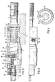
- Fig. 1 einen Schnitt durch einen Maschinenschraubstock mit einem erfindungsgemäßen Antrieb,
- Fig. 2 eine vergrößerte Schnittdarstellung des erfindungsgemäßen Antriebs,
- Fig. 3 eine teilweise Draufsicht auf die Darstellung der Fig. 2 und
- Fig. 4 eine Ansicht der Kurbelseite des Antriebs.
- 1 shows a section through a machine vice with a drive according to the invention,
- 2 is an enlarged sectional view of the drive according to the invention,
- Fig. 3 is a partial plan view of the illustration of Fig. 2 and
- Fig. 4 is a view of the crank side of the drive.
In der Darstellung der Fig. 1 ist auf dem Schraubstockkörper 8 an dem einen Ende die Backe 9 fest angeordnet. Am anderen Ende des Schraubstockkörpers ist das Widerlager 6 vorgesehen, das den erfindungsgemäßen Antrieb 28 aufnimmt. Im Schraubstockkörper 8 ist der Schlitten 29 gelagert, der die bewegliche Backe 4 trägt. Die Vorschubbewegung für den Schlitten 29 erfolgt mittels der Schraubspindel 1. Diese greift mit dem Schraubspindelgewinde 30 in die Spindelmutter 10 ein, die sich über die ganze Länge der Spindel erstreckt. Die Fig. 1 zeigt diejenige Stellung des Maschinenschraubstockes 5, in der die Backe 4 ganz zurückgezogen ist. Die Vorschubbewegung wird über die Kurbel 3, die auf den Mehrkant 31 aufsteckbar ist, in den Antrieb eingeleitet.1, the
Aus der Fig. 2 ergibt sich, daß die Schraubspindel 1 mit einer Verlängerung 13 in die Bohrung 12 der Hülse 11 hineinragt. Ein Keilstift 32 verbindet die Hülse 11 und die Verlängerung 13 der Schraubspindel 1. Die Ausnehmung 33 in der Hülse 11 ist dabei als Langloch gestaltet, um eine Axialbewegung des Keilstiftes 32 und damit der Schraubspindel 1 gegenüber der Hülse 11 zuzulassen.From Fig. 2 it follows that the screw 1 protrudes with an extension 13 into the bore 12 of the sleeve 11. A
Die Hülse 11 stützt sich mit der Abstützfläche 40 des Ringflansches 7 am Widerlager 6 ab. Zur Übertragung der Presßdrücke der Schraubspindel 1 auf die Hülse 11 ist eine Abstufung 34 vorgesehen.The sleeve 11 is supported on the abutment 6 with the
Die Hülse 11 und die Schraubspindel 1 bilden das eine Teil des Antriebes, der in der Darstellung der Fig. 2 von rechts in die Bohrung des Widerlagers 6 eingeführt wird. Die in der Darstellung der Fig. 2 links vom Widerlager 6 angeordneten Elemente des Antriebes werden mit dem Teil 20 der Kammer 15 auf das Außengewinde 14 der Hülse 11 aufgeschraubt. Mittels einer Sicherungsschraube 36, für die beispielsweise zwei um 180 Grad gegenüberliegende längliche Ausnehmungen 37 in der Hülse 11 vorgesehen sind, läßt sich leicht erreichen, daß beim Aufschrauben des Teiles 20 auf die Hülse 11 eine gute Anpassung an die Abmessungen des Widerlagers 6 erfolgt. Die Verbindung wird nur ein sehr geringes Spiel besitzen.The sleeve 11 and the screw 1 form one part of the drive, which in the illustration of FIG. 2 from the right into the Bore of the abutment 6 is inserted. The elements of the drive arranged to the left of the abutment 6 in the illustration in FIG. 2 are screwed with the
Die Teile 19 und 20 bilden zusammen die Kammer 15, die den Kraftverstärker 2 aufnimmt, der in seinen Einzelheiten nicht näher dargestellt ist.The
Im Innengewinde 17 des Teiles 19 ist die Kurbelwelle 16 gehalten, die beim Hineinschrauben in das Teil 19 bzw. in die Kammer 15 auf den Kraftverstärker einwirkt. Die Kupplung 18 in der Kammer 15 besteht aus einer Kugel 35, die unter der Wirkung einer Feder 38 steht und die in eine Ausnehmung 39 des Teiles 19 teilweise hineinragt. Die Kraft der Feder 38 bestimmt, welches Drehmoment zwischen der Kurbel 16 und dem Teil 19 übertragbar ist. Ist das eingestellte Drehmoment überschritten, bewegt sich die Kugel 35 gegen die Kraft der Feder 38 nach innen und es wird eine Einschraubbewegung der Kurbel 16 in die Kammer 15 möglich.The
Auf der Kurbelwelle 16 ist eine Schwenkwinkelbegrenzung 21 vorgesehen, die im wesentlichen aus einer Ringnut 22 im Teil 19 besteht, in die ein Stift 24 eingreift. Die Ringnut besitzt einen Endanschlag 23 (vgl. Fig. 4), so daß der Stift 24 einen maximalen Schwenkweg von etwa 300 Grad besitzt. Da der Stift 24 im Stellring 26 gelagert ist und der Stellring 26 auf dem Mehrkant 27 mit sechs Flächen gegen die Kraft der Feder 25 verschiebbar ist, ist es möglich, den Stellring 26 in der Darstellung der Fig. 2 nach links gegen die Kraft der Feder zurückzuziehen, wobei der Mehrkant 27 ausrastet und in verschiedenen Stellungen auf dem Sechskant 27 zu fixieren. Dabei können insgesamt fünf verschiedene Stellungen (Stellung 1 bis 5 der Fig. 4) eingenommen werden. In der Stellung 1 ist nur eine Schwenkbewegung von 60 Grad möglich, also nur eine geringe Betätigung des Kraftverstärkers 2. In den anderen Stellungen ergibt sich dagegen eine stärkere Wirksamkeit des Kraftverstärkers.On the
Beim praktischen Gebrauch wird mittels des beschriebenen Antriebs, also unter Verwendung der Kurbel 3, die bewegliche Backe 4 so weit vorangeschoben, bis das zwischen den Backen 4 und 9 eingespannte Werkstück mit einer, von der Kupplung 18 bestimmten Kraft, festgehalten ist. Bei dieser Bewegung wird die Schraubspindel gedreht. Rastet die Kugel 35 aus, tritt der Kraftverstärker 2 in Tätigkeit, der über die Verlängerung 13 eine axiale Vorschubkraft auf die Schraubspindel ausübt, ohne diese zu verdrehen. Die Schwenkwinkelbegrenzung 21 sichert eine genau vorherbestimmbare und reproduzierbare Spannkraft.In practical use, by means of the drive described, that is to say using the crank 3, the movable jaw 4 is pushed so far until the workpiece clamped between the
Claims (11)
Applications Claiming Priority (2)
| Application Number | Priority Date | Filing Date | Title |
|---|---|---|---|
| DE8806051U | 1988-05-06 | ||
| DE8806051U DE8806051U1 (en) | 1988-05-06 | 1988-05-06 |
Publications (2)
| Publication Number | Publication Date |
|---|---|
| EP0340602A1 EP0340602A1 (en) | 1989-11-08 |
| EP0340602B1 true EP0340602B1 (en) | 1992-07-01 |
Family
ID=6823803
Family Applications (1)
| Application Number | Title | Priority Date | Filing Date |
|---|---|---|---|
| EP89107420A Expired - Lifetime EP0340602B1 (en) | 1988-05-06 | 1989-04-25 | Drive for a machine vice |
Country Status (6)
| Country | Link |
|---|---|
| US (1) | US4934676A (en) |
| EP (1) | EP0340602B1 (en) |
| JP (1) | JP2758202B2 (en) |
| KR (1) | KR890017043A (en) |
| DE (2) | DE8806051U1 (en) |
| ES (1) | ES2034468T3 (en) |
Families Citing this family (3)
| Publication number | Priority date | Publication date | Assignee | Title |
|---|---|---|---|---|
| US5273264A (en) * | 1992-12-18 | 1993-12-28 | Safeway Machinery Industry Corp. | Pneumatic quick vise |
| US6164635A (en) * | 1999-05-21 | 2000-12-26 | Chase; Donald | Milling machine bench vise |
| US20070138724A1 (en) * | 2005-12-16 | 2007-06-21 | Black & Decker | Clamp Device |
Family Cites Families (13)
| Publication number | Priority date | Publication date | Assignee | Title |
|---|---|---|---|---|
| US3397880A (en) * | 1966-05-10 | 1968-08-20 | Kurt Mfg Company | Vise clamp |
| DE2308175C3 (en) * | 1973-02-19 | 1975-09-04 | Saurer-Allma Gmbh, Allgaeuer Maschinenbau, 8960 Kempten | Toggle booster |
| US3941362A (en) * | 1973-09-17 | 1976-03-02 | Saurer-Allma Gmbh, Allgaeuer Maschinenbau | Clamping device, in particular a machine vise |
| IT1116739B (en) * | 1976-06-14 | 1986-02-10 | Arnold Franz | SOCKET DEVICE, PARTICULARLY SCREW VICE FOR MACHINES |
| US4043547A (en) * | 1976-12-10 | 1977-08-23 | Chicago Tool And Engineering Company | Precision machine vise |
| DE2710424A1 (en) * | 1977-03-10 | 1978-09-14 | Roehm Guenter H | CLAMPING DEVICE, IN PARTICULAR MACHINE VICE |
| DE2832427A1 (en) * | 1978-07-24 | 1980-02-07 | Franz Schoeffel | Machine vice with adjustable pressure - has radial cam disc exerting clamping force with amplification |
| DE7830221U1 (en) * | 1978-10-11 | 1980-03-20 | Arnold, Franz, 8960 Kempten | MECHANICAL POWER AMPLIFIER |
| DE2909451C2 (en) * | 1979-03-10 | 1982-06-16 | Georg Kesel GmbH & Co KG, 8960 Kempten | Clamping devices, in particular for machine vices |
| IT1168021B (en) * | 1980-10-22 | 1987-05-20 | Saurer Allma Gmbh | PNEUMATICALLY OPERATED LOCKING DEVICE, IN PARTICULAR MACHINE VICE |
| DE3437403A1 (en) * | 1984-10-12 | 1986-04-24 | Saurer-Allma Gmbh, 8960 Kempten | HIGH PRESSURE TENSIONER |
| DE3438900C2 (en) * | 1984-10-24 | 1986-08-21 | Saurer-Allma Gmbh, 8960 Kempten | Machine vise |
| US4605208A (en) * | 1985-04-04 | 1986-08-12 | Durham Randy E | Combination automatic and manual vise apparatus |
-
1988
- 1988-05-06 DE DE8806051U patent/DE8806051U1/de not_active Expired
- 1988-12-01 US US07/278,352 patent/US4934676A/en not_active Expired - Lifetime
-
1989
- 1989-04-25 ES ES198989107420T patent/ES2034468T3/en not_active Expired - Lifetime
- 1989-04-25 DE DE8989107420T patent/DE58901758D1/en not_active Expired - Fee Related
- 1989-04-25 EP EP89107420A patent/EP0340602B1/en not_active Expired - Lifetime
- 1989-05-02 JP JP1112348A patent/JP2758202B2/en not_active Expired - Lifetime
- 1989-05-04 KR KR1019890005991A patent/KR890017043A/en not_active Application Discontinuation
Also Published As
| Publication number | Publication date |
|---|---|
| ES2034468T3 (en) | 1993-04-01 |
| JPH0215980A (en) | 1990-01-19 |
| EP0340602A1 (en) | 1989-11-08 |
| DE8806051U1 (en) | 1988-06-30 |
| JP2758202B2 (en) | 1998-05-28 |
| US4934676A (en) | 1990-06-19 |
| DE58901758D1 (en) | 1992-08-06 |
| KR890017043A (en) | 1989-12-14 |
Similar Documents
| Publication | Publication Date | Title |
|---|---|---|
| EP0480299B1 (en) | Multiple clamping device for clamping at least two workpieces | |
| DE4237422C2 (en) | Workpiece holding device for workpieces to be machined on multiple sides on machine tools | |
| DE2257384C3 (en) | Chucks for lathes and the like machine tools | |
| EP0463344B1 (en) | Chucking device with power assist, especially machine vice | |
| DE4112418A1 (en) | MACHINE VICE | |
| DE3603618C1 (en) | Clamping device for use on machine tools | |
| DE3601225C1 (en) | Interchangeable head for a tool changing device | |
| DE2060881A1 (en) | Mechanical clamping device, in particular machine vice | |
| DE3003626A1 (en) | Work clamp with spring loaded clamping arm - has screw and nut to tilt clamping arm about hinge axis inside housing | |
| DE3925717A1 (en) | DEVICE ON MACHINE VICE FOR CENTRICALLY CLAMPING WORKPIECES | |
| EP0340602B1 (en) | Drive for a machine vice | |
| DE3329942C1 (en) | Clamping device in particular for workpieces to be machined | |
| DE3729093C1 (en) | Clamping device with mechanical power amplifier | |
| DE851579C (en) | Device for eliminating the axial play of gearboxes | |
| DE2631583B2 (en) | Power operated chuck | |
| EP0013746B1 (en) | Clamping device for workpieces | |
| DE898839C (en) | Device and method for the arbitrary elimination and activation of the dead gear in spindle drives | |
| DE2648997A1 (en) | Machine tool chuck with independent jaws - has jaws tightened inwardly by collet action once separate positions have been set | |
| DE1810722B2 (en) | Chuck clamping jaw radial adjustment system - uses spiral disc with engaged bush rotatable around chuck housing and has wedge surfaces | |
| DE4025745C2 (en) | ||
| EP0499808B1 (en) | Vice with power amplifier | |
| DE2808272C2 (en) | Chuck | |
| DE2166393C3 (en) | Turret device | |
| DE202004010936U1 (en) | Linear feed tool is used on a CNC machine tool for cutting keyway grooves and uses tool mounted on tool changer | |
| DE2632528A1 (en) | POWER-OPERATED CHUCK FOR LATHE |
Legal Events
| Date | Code | Title | Description |
|---|---|---|---|
| PUAI | Public reference made under article 153(3) epc to a published international application that has entered the european phase |
Free format text: ORIGINAL CODE: 0009012 |
|
| AK | Designated contracting states |
Kind code of ref document: A1 Designated state(s): DE ES FR IT |
|
| 17P | Request for examination filed |
Effective date: 19891206 |
|
| 17Q | First examination report despatched |
Effective date: 19910314 |
|
| GRAA | (expected) grant |
Free format text: ORIGINAL CODE: 0009210 |
|
| AK | Designated contracting states |
Kind code of ref document: B1 Designated state(s): DE ES FR IT |
|
| ITF | It: translation for a ep patent filed |
Owner name: BUGNION S.P.A. |
|
| ET | Fr: translation filed | ||
| REF | Corresponds to: |
Ref document number: 58901758 Country of ref document: DE Date of ref document: 19920806 |
|
| REG | Reference to a national code |
Ref country code: ES Ref legal event code: FG2A Ref document number: 2034468 Country of ref document: ES Kind code of ref document: T3 |
|
| PLBE | No opposition filed within time limit |
Free format text: ORIGINAL CODE: 0009261 |
|
| STAA | Information on the status of an ep patent application or granted ep patent |
Free format text: STATUS: NO OPPOSITION FILED WITHIN TIME LIMIT |
|
| 26N | No opposition filed | ||
| PGFP | Annual fee paid to national office [announced via postgrant information from national office to epo] |
Ref country code: FR Payment date: 20000417 Year of fee payment: 12 |
|
| PGFP | Annual fee paid to national office [announced via postgrant information from national office to epo] |
Ref country code: ES Payment date: 20000426 Year of fee payment: 12 |
|
| PG25 | Lapsed in a contracting state [announced via postgrant information from national office to epo] |
Ref country code: ES Free format text: LAPSE BECAUSE OF NON-PAYMENT OF DUE FEES Effective date: 20010426 |
|
| PG25 | Lapsed in a contracting state [announced via postgrant information from national office to epo] |
Ref country code: FR Free format text: THE PATENT HAS BEEN ANNULLED BY A DECISION OF A NATIONAL AUTHORITY Effective date: 20010430 |
|
| PGFP | Annual fee paid to national office [announced via postgrant information from national office to epo] |
Ref country code: DE Payment date: 20010623 Year of fee payment: 13 |
|
| REG | Reference to a national code |
Ref country code: FR Ref legal event code: ST |
|
| PG25 | Lapsed in a contracting state [announced via postgrant information from national office to epo] |
Ref country code: DE Free format text: LAPSE BECAUSE OF NON-PAYMENT OF DUE FEES Effective date: 20021101 |
|
| REG | Reference to a national code |
Ref country code: ES Ref legal event code: FD2A Effective date: 20030203 |
|
| PG25 | Lapsed in a contracting state [announced via postgrant information from national office to epo] |
Ref country code: IT Free format text: LAPSE BECAUSE OF NON-PAYMENT OF DUE FEES;WARNING: LAPSES OF ITALIAN PATENTS WITH EFFECTIVE DATE BEFORE 2007 MAY HAVE OCCURRED AT ANY TIME BEFORE 2007. THE CORRECT EFFECTIVE DATE MAY BE DIFFERENT FROM THE ONE RECORDED. Effective date: 20050425 |