EP0339855A2 - Elektrodynamischer Lautsprecher - Google Patents
Elektrodynamischer Lautsprecher Download PDFInfo
- Publication number
- EP0339855A2 EP0339855A2 EP89303854A EP89303854A EP0339855A2 EP 0339855 A2 EP0339855 A2 EP 0339855A2 EP 89303854 A EP89303854 A EP 89303854A EP 89303854 A EP89303854 A EP 89303854A EP 0339855 A2 EP0339855 A2 EP 0339855A2
- Authority
- EP
- European Patent Office
- Prior art keywords
- diaphragm
- loudspeaker
- conductive portion
- feeding coil
- current feeding
- Prior art date
- Legal status (The legal status is an assumption and is not a legal conclusion. Google has not performed a legal analysis and makes no representation as to the accuracy of the status listed.)
- Granted
Links
Images


Classifications
-
- H—ELECTRICITY
- H04—ELECTRIC COMMUNICATION TECHNIQUE
- H04R—LOUDSPEAKERS, MICROPHONES, GRAMOPHONE PICK-UPS OR LIKE ACOUSTIC ELECTROMECHANICAL TRANSDUCERS; ELECTRIC HEARING AIDS; PUBLIC ADDRESS SYSTEMS
- H04R9/00—Transducers of moving-coil, moving-strip, or moving-wire type
-
- H—ELECTRICITY
- H04—ELECTRIC COMMUNICATION TECHNIQUE
- H04R—LOUDSPEAKERS, MICROPHONES, GRAMOPHONE PICK-UPS OR LIKE ACOUSTIC ELECTROMECHANICAL TRANSDUCERS; ELECTRIC HEARING AIDS; PUBLIC ADDRESS SYSTEMS
- H04R1/00—Details of transducers, loudspeakers or microphones
- H04R1/20—Arrangements for obtaining desired frequency or directional characteristics
- H04R1/32—Arrangements for obtaining desired frequency or directional characteristics for obtaining desired directional characteristic only
- H04R1/34—Arrangements for obtaining desired frequency or directional characteristics for obtaining desired directional characteristic only by using a single transducer with sound reflecting, diffracting, directing or guiding means
- H04R1/345—Arrangements for obtaining desired frequency or directional characteristics for obtaining desired directional characteristic only by using a single transducer with sound reflecting, diffracting, directing or guiding means for loudspeakers
-
- H—ELECTRICITY
- H04—ELECTRIC COMMUNICATION TECHNIQUE
- H04R—LOUDSPEAKERS, MICROPHONES, GRAMOPHONE PICK-UPS OR LIKE ACOUSTIC ELECTROMECHANICAL TRANSDUCERS; ELECTRIC HEARING AIDS; PUBLIC ADDRESS SYSTEMS
- H04R9/00—Transducers of moving-coil, moving-strip, or moving-wire type
- H04R9/02—Details
-
- H—ELECTRICITY
- H04—ELECTRIC COMMUNICATION TECHNIQUE
- H04R—LOUDSPEAKERS, MICROPHONES, GRAMOPHONE PICK-UPS OR LIKE ACOUSTIC ELECTROMECHANICAL TRANSDUCERS; ELECTRIC HEARING AIDS; PUBLIC ADDRESS SYSTEMS
- H04R9/00—Transducers of moving-coil, moving-strip, or moving-wire type
- H04R9/02—Details
- H04R9/04—Construction, mounting, or centering of coil
- H04R9/045—Mounting
-
- H—ELECTRICITY
- H04—ELECTRIC COMMUNICATION TECHNIQUE
- H04R—LOUDSPEAKERS, MICROPHONES, GRAMOPHONE PICK-UPS OR LIKE ACOUSTIC ELECTROMECHANICAL TRANSDUCERS; ELECTRIC HEARING AIDS; PUBLIC ADDRESS SYSTEMS
- H04R2209/00—Details of transducers of the moving-coil, moving-strip, or moving-wire type covered by H04R9/00 but not provided for in any of its subgroups
- H04R2209/043—Short circuited voice coils driven by induction
Definitions
- This invention relates to loudspeakers.
- a dynamic type loudspeaker by allowing an audio signal current to flow through a voice coil in a dc magnetic field, a driving force is obtained.
- the audio signal current is usually supplied from the exterior to a voice coil through lead wires fixed to a paper cone which forms a diaphragm.
- the lead wires may break due to elastic fatigue or the like caused by the reciprocating motion of the diaphragm.
- the linearity of the reciprocating motion of the diaphragm may be impaired by the spring force of the lead wires, so sound distortion occurs, or the lead wires themselves may resonate and generate an abnormal sound.
- the lead wires must be led out from a narrow gap in the loudspeaker and must be positioned, adhered, and fixed, the assembly thereof troublesome.
- an induction type loudspeaker from which lead wires are eliminated has been disclosed in Japanese Patent Application publication 56/27039.
- this loudspeaker the lead wires are eliminated and a driving coil is arranged near a voice coil wound around a voice coil bobbin.
- An audio signal current is supplied to the driving coil, and the audio signal is supplied from the driving coil to the voice coil by magnetic induction. That is, when an ac signal of audio frequency flows from an electric power amplifier to the driving coil, an ac magnetic flux corresponding to the input waveform is generated by the driving coil.
- This ac magnetic flux closely interlinks with the voice coil which is located very close, and since the voice coil itself is short-circuited, a short-circuit current flows through the voice coil due to the ac magnetic flux. Since the voice coil is located in the magnetic field which is produced by a pole piece and peripheral magnetic poles, a force which is proportional to the product of the intensity of the magnetic field and the short-circuit current acts on the voice coil. This force is transferred from the voice coil to the voice coil bobbin, and vibrates a cone-shaped diaphragm, so sound is generated as in an ordinary loudspeaker.
- the voice coil is generally fixed to the voice coil bobbin by an adhesive agent, it is difficult for the driving force generated in the voice coil to be directly transferred to the diaphragm.
- the voice coil generates heat due to the short-circuit current therein, and it is difficult to radiate the heat satisfactorily.
- the voice coil bobbin is made of paper, it may become carbonized.
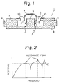
- an induction type loudspeaker 1 shown in Figure 1 comprises diaphragm 4 having an annular conductive portion 3 supported to vibrate freely in an annular magnetic gap portion 2 by a damper 10.
- a current feeding coil fixedly arranged on the side of a magnetic circuit is mechanically separated from the diaphragm 4 as a vibration system, and is electrically coupled with the conductive portion 3 by mutual inductance.
- the magnetic gap portion 2 is annular and formed between a top plate 7, and a centre pole 9 of a yoke plate 8, which together with a magnet 6, for example of ferrite, form a magnetic circuit.
- the damper 10 is secured to the top plate 7.
- the diaphragm 4 may be dome-shaped with the conductive portion 3 at its open edge portion. Therefore, the whole diaphragm 4 is made from a thin plate of a good conductor, such as aluminium, beryllium or magnesium. Moreover, since the current feeding coil 5 is to be mechanically separated from the diaphragm 4 and electrically coupled with the conductive portion 3, the current feeding coil 5 is arranged so as to face the outer or inner periphery of the conductive portion 3. In this case, the current feeding coil 5 is fixed to the outer periphery of the centre pole 9.
- This loudspeaker 1 operates as follows.
- the diaphragm In this loudspeaker not only the lead wires but also the voice coil are eliminated, but there are still problems.
- the diaphragm must normally be formed of a metal because it is necessary to develop the induced current in the conductive portion thereof.
- a metal diaphragm is heavy, so the sensitivity of the loudspeaker is reduced.
- the mechanical loss is small and the diaphragm is relatively heavy, there is a problem that the frequency characteristic of the loudspeaker is not flat, and sharp resonance peaks appear, as shown in Figure 2, at which it is difficult to brake the diaphragm, and at which the sound quality deteriorates.
- the conductive portion of the diaphragm and the portions other than the conductive portion in the diaphragm are not insulated, there is a problem of leakage of the induced current. Since the leakage current is not useful in driving the diaphragm, the driving force is weakened, and again the response sensitivity of the loudspeaker deteriorates.
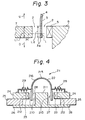
- the diaphragm 4 reciprocates in the directions U and D in Figure 3 due to the induced current, and it is assumed that a uniform magnetic field range L1 of the dc magnetic field having a uniform magnetic flux distribution and a length L2 of the conductive portion 3 are substantially equal.
- the amplitude of the diaphragm 4 should increase in accordance with the induced current, but when the conductive portion 3 is largely out of the uniform magnetic field range L1, since the driving force is reduced, the amplitude of the diaphragm 4 does not respond accurately to changes in the audio signal, so linearity is lost, and distortion occurs.
- a loudspeaker comprising: a diaphragm comprising a vibrating portion and an annular conductive portion; a current feeding coil facing said conductive portion with a predetermined gap; and a magnetic circuit to which said current feeding coil is attached; characterized in that: said diaphragm is formed so that the electric resistance of said conductive portion is lower than the electric resistance of said vibrating portion.
- ac magnetic flux when an ac audio signal is allowed to flow through the current feeding coil, ac magnetic flux is generated. Since the annular conductive portion closely interlinks with this ac magnetic flux, current of the same frequency is induced in the conductive portion by mutual inductance. Since the electric resistance of the conductive portion is lower than the electric resistance of the vibrating portion, the induced current can more easily flow through the conductive portion. However, it is more difficult for the induced current to flow through the vibrating portion. Thus, a larger induced current flows through the conductive portion, and the generation of leakage current which is not useful to drive the diaphragm can be prevented.
- the induced current acts on the dc magnetic field in the magnetic gap portion and vibrates the diaphragm, since the leakage current is eliminated, the driving force on the diaphragm can be increased, so the sensitivity of the loudspeaker can be improved.
- the weight of the diaphragm can be reduced, so the response sensitivity of the loudspeaker can be improved.
- a loudspeaker comprising: a diaphragm provided with an annular conductive portion; a current feeding coil facing said conductive portion with a predetermined gap; and a magnetic circuit to which said current feeding coil is attached; characterized by: a capacitor which forms a high-pass filter together with internal resistance of said current feeding coil connected serially with said current feeding coil.
- a loudspeaker comprising: a diaphragm made of a non-conductive material; a current feeding coil; and a magnetic circuit to which said current feeding coil is attached; characterized by: an annular conductive portion which is arranged at an edge portion of said diaphragm so as to be integrated with said diaphragm; said current feeding coil being arranged to face said conductive portion with a predetermined gap.
- a loudspeaker comprising: a diaphragm having an annular conductive portion; a current feeding coil facing said conductive portion with a predetermined gap; and a magnetic circuit to which said current feeding coil is attached; characterized in that: a length in the vibrating direction of said diaphragm of one of said conductive portion and said current feeding coil is made to be greater than a length in the vibrating direction of said diaphragm of the other one of said conductive portion and said current feeding coil.
- a loudspeaker comprising: a diaphragm having an annular conductive portion; a current feeding coil facing said conductive portion with a predetermined gap; and a magnetic circuit to which said current feeding coil is attached; characterized in that: a damper which is attached to said magnetic circuit and supports said diaphragm so as to vibrate freely is formed integrally with said conductive portion.
- a loudspeaker comprising: a diaphragm having an annular conductive portion; a current feeding coil arranged to face said conductive portion with a predetermined gap; and a magnetic circuit to which said current feeding coil is attached; characterized by: means for raising the coupling coefficient of said conductive portion and said current feeding coil.
- Figure 4 shows the first embodiment in which a loudspeaker 21 comprises a diaphragm 22, a damper 29, a current feeding coil 23 acting as a primary coil, a top plate 24, a magnet 25, a yoke plate 26, and a pole piece 211.
- the diaphragm 22 is dome-shaped and comprises a vibrating portion 215 of hemispherical shape, and a conductive portion 28 acting as a secondary coil which is a thick annulus at an edge portion 27.
- the whole diaphragm 22 is made of a good conductor such as a metal like aluminium, beryllium or magnesium.
- the diaphragm 22 is supported by the damper 29 so as to vibrate freely with the conductive portion 28 located in a magnetic gap portion 210 which is of annular shape and formed between the top plate 24 and the pole piece 211 of the yoke plate 26.
- the damper 29 has a spring characteristic and is annularly formed.
- the inner peripheral side of the damper 29 is connected to the periphery of the conductive portion 28 and the outer peripheral side is fixed to the top plate 24.
- the current feeding coil 23 acting as a primary coil allows the conductive portion 28 to be electrically coupled by mutual inductance and is arranged so as to face the conductive portion 28 with a predetermined gap.
- the current feeding coil 23 can face the outer or inner periphery of the conductive portion 28 or both.
- the current feeding coil 23 in the example shown faces the outer periphery and is fixed to one side edge surface 212 of the top plate 24.
- the current feeding coil 23 would be fixed to the side of an outer periphery 213 of the pole piece 211.
- the current feeding coil 23 may alternatively be in both these positions.
- the current feeding coil 23 may be attached to the top plate 24 on the pole piece 211 as shown in Figures 11 to 14, so more effectively conducting the heat generated in the current feeding coil 23 to the top plate 24 or the pole piece 211. Therefore, it is possible to prevent the current feeding coil 23 falling off due to over heating of the adhesive, and also to locate the current feeding coil more precisely. Attachment of the current feeding coil will now be briefly described. The structures shown in Figures 11 to 14 can be applied to the other embodiments which will be described later.
- a step portion 24a which forms a positioning means for the current feeding coil 23 is formed on a side of the inner periphery of the top plate 24, and the current feeding coil 23 is fixed to the step portion 24a by an adhesive.
- the height of the current feeding coil 23 can always be made the same, and as the positioning of the current feeding coil 23 is made easy, productivity can be improved.
- an edge portion of the current feeding coil 23 is against the step portion 24a conduction is improved, and the possibility of breakdown due to vibration in operation with a large input is reduced.
- a step portion 211a which forms positioning means for the current feeding coil 23 is formed on a side of the outer periphery of the pole piece 211, and the current feeding coil 23 is fixed to the step portion 211a by an adhesive.
- actions and effects similar to the example of Figure 11 can be achieved.
- a pressing member 24b preferably comprising a material having a good heat conductivity is fixed to the opposite side of the top plate 24 to the step portion 24a by an adhesive. Otherwise the construction is similar to that of Figure 11.
- a pressing member 211b preferably comprising a material having a good heat conductivity is fixed to the opposite side of the top plate 24 to the step portion 211a by an adhesive. Otherwise the construction is similar to that of Figure 12.
- a magnetic circuit is formed by the top plate 24, the magnet 25, the yoke plate 26, and the pole piece 211. As shown in Figure 4, the magnetic 25 is fixed to the outer peripheral portion on the yoke plate 26, and the top plate 24 is fixed to the outer peripheral portion of the magnet 25.
- the magnetic circuit is formed through the magnetic gap portion 210 along a path from the magnet 25 to the top plate 24, and a path from the magnet 25 to the yoke plate 26 and pole piece 211.
- a cylindrical member 216 is pressed to form the diaphragm integrally, such that the vibrating portion 215 is as thin as possible and the conductive portion 28 is thick.
- the conductive portion 28 is of increased cross sectional area and the vibrating portion 215 is of reduced cross sectional area, thereby reducing the weight of the whole diaphragm 22.
- the resistance of the conductive portion 28 is reduced and the resistance of the vibrating portion 215 is increased.
- an ac magnetic flux corresponding to the input waveform is generated. Since the annular conductive portion 28 closely interlinks the ac magnetic flux, current of the same frequency is induced in the conductive portion 28 by mutual inductance. Since the conductive portion 28 is located in the magnetic gap portion, a force which is proportional to the product of the intensity of the dc magnetic field in the magnetic gap portion 210 and the induced current acts on the conductive portion 28. That is, the induced current in the conductive portion 28 acts on the dc magnetic field in the magnetic gap portion 210 and directly drives the diaphragm 22, so that a sound wave is generated.
- the weight of the diaphragm 22 can be reduced, and the response sensitivity of the loudspeaker 21 can be improved.
- a larger induced current flows through the conductive portion 28 and the generation of a leakage current can be prevented, and the driving force on the diaphragm 22 can be increased, improving the response sensitivity of the loudspeaker 21.
- Figure 5 shows an example of the formation of the diaphragm 22 in the second embodiment.
- the thickness of the cylindrical member 216 in the range corresponding to the vibrating portion 215 is reduced by cutting.
- An outer peripheral surface 217 of the cylindrical member 216 having a thickness t16 as shown in Figure 5A is cut to a thickness of t15 which is as thin as possible, while only a lower portion 218 is left.
- the diaphragm 22 as shown in Figure 5B is formed. That is, the diaphragm 22 comprises the thin vibrating portion 215 which is cut in thickness from t16 to t15, and the thick conductive portion 28 having the non-cut thickness of t16.
- an oxidizing treatment what is called an alumite treatment is particularly effective. In such a case, if black alumite treatment is used, a good design can be obtained and the heat radiation is also improved.
- Figure 6 shows an example of the formation of the diaphragm 22 in the third embodiment, in which an edge portion 230 of the cylindrical member 216 formed to have the necessary least thickness is turned back to form the annular conductive portion 218.
- a pressing method or another suitable method can be used for forming the diaphragm 22. Otherwise this embodiment is similar to the first embodiment.
- Figure 7 shows an example of the formation of the diaphragm 22 in the fourth embodiment, in which the thickness t8 of the conductive portion 28 of the cylindrical member 216 is increased to a thickness t16 by plating. Otherwise this embodiment is the same as the first embodiment.
- a metal such as gold, silver, or copper of good conductivity is plated only on the lower portion 218 of the outer peripheral surface 217 of the cylindrical member 216 which is formed with the necessary least thickness as shown in Figure 7A. That is, the diaphragm 22 is formed by the thin vibrating portion 215 which is not plated and has the thickness t15, and the thick conductive portion 28 on the outside of which the plated portion 236 is formed and has the thickness t8.
- Figure 7C shows a diaphragm 22 in which the plated portion 236 is formed on an inner peripheral surface 235 of the cylindrical member 216.
- Figure 7D shows a diaphragm 22 in which the plated portion 236 is formed on the inner and outer peripheral surfaces 235 and 217.
- sputtering can be used.
- Figure 8 shows an example of the forming of the diaphragm 22 in the fifth embodiment, in which the thickness of the conductive portion 28 is increased from the thickness of t16 to the thickness t8 by fitting a conductive ring 240 to the edge portion 230 of the cylindrical member 216. Otherwise this embodiment is the same as the first embodiment.
- the conductive ring 240 which is formed of a material of good conductivity is fitted to the outer peripheral surface 217 of the lower portion 218 of the cylindrical member 216.
- Figure 9 shows an example of the forming of the diaphragm 22 in the sixth embodiment of the invention, in which the vibrating portion 215 of the diaphragm 22 which is thinly formed, has a number of holes formed in a non-passing portion 245 through which the dc magnetic field does not pass.
- the non-passing portion 245 denotes the lowest edge portion within a range where the dc magnetic field does not pass in the case where the diaphragm 22 moves in the direction DO to the lowest position P.
- a number of circular holes 246 are formed in the non-passing portion 245.
- a number of circumferentially elongated holes 247 are formed in the non-passing portion 245.
- a number of axially elongated holes 248 are formed in the non-passing portion 245.
- the weight of the diaphragm 22 is reduced.
- the cross sectional area of the current flowing portion is reduced, thereby raising the resistance and preventing the generation of a leakage current.
- the high-band limit can be controlled in dependence on the holes 246, 247 or 248, and the sound quality can be controlled.
- the sound quality can be controlled in dependence on the holes 246, 247 or 248, and the sound quality can be controlled.
- the circumferentially elongated holes 247 shown in Figure 9B it is difficult to generate the high-band sound.
- the axially elongated holes 248 shown in Figure 9C high-band sound can easily be generated.
- the whole diaphragm 22 is formed of a good conductor consisting of a metal and the thickness of the diaphragm 22 is partially changed to change the electric resistance, and as a result the weight of the diaphragm itself is reduced.
- the diaphragm 22 itself of a non-conductive material and forming the conductive portion 28 only of a good conductor and fixing it to the diaphragm 22, it is possible for the weight of the diaphragm 22 to be reduced, since the material of the diaphragm 22 itself can be selected suitably, thereby achieving effects similar to the first to sixth embodiments.
- Such a construction will now be described.
- Figure 15 shows the seventh embodiment in which a cylindrical pole piece 52 is formed at the centre of a disc-shaped yoke plate 51.
- a ring-shaped magnet 53 is laminated and fixed onto the yoke plate 51.
- a ring-shaped top plate 54 is laminated and fixed onto the magnet 53.
- An outer magnet type magnetic circuit is formed by the yoke plate 51, the pole piece 52, the magnet 53, and the top plate 54.
- a current feeding coil 55 is wound around the inner periphery of the top plate 54. Lead wires 59A and 59B are led out form the current feeding coil 55.
- a dome-shaped diaphragm 56 is formed of a non-conductive material, for example, polymeric film, ceramics, cloth or paper.
- a conductive portion 57 is integrally arranged at an edge portion of the diaphragm 56.
- a metallic ring is fitted on and attached to the outer periphery of the edge portion of the diaphragm 56, thereby forming the conductive portion 57 which operates as a voice coil of one turn or a few turns as in an ordinary dynamic loudspeaker.
- a magnetic gap is formed where the outer periphery of the pole piece 52 faces the inner periphery of the top plate 54, and the conductive portion 57 lies in the magnetic gap.
- the diaphragm 56 is supported by a damper 58 so as to vibrate freely.
- the damper 58 may alternatively be formed integrally with the diaphragm 56.
- the loudspeaker is driven by supplying an ac signal corresponding to an audio signal to terminals 510A and 510B of the lead wires 59A and 59B.
- a magnetic flux is generated in the current feeding coil 55 by the ac signal and interlinks with the conductive portion 57 which faces the current feeding coil 55.
- an induced current flows in the conductive portion 57, and a force to move the conductive portion 57 is generated, so that the diaphragm 56 is vibrated.
- the force generated in the conductive portion 57 is directly transferred to the diaphragm 56. Therefore, a situation in which a coupling portion obstructs the vibration and deteriorates the sound quality as in a known loudspeaker in which the voice coil bobbin is fixed by adhesive, does not occur. Moreover, since the diaphragm 56 is made of a non-conductive material, loss due to a leakage current such as occurs in the case where the whole diaphragm 56 is metallic does not occur.
- Figures 18 to 21 show the case where a metal ring is fitted as the conductive portion 57 to the diaphragm 56 of non-conductive material, and the diaphragm 56 and the conductive portion 57 are mechanically integrated.
- a diameter l1 of the outer periphery of the edge portion of the diaphragm 56 corresponds to a diameter l2 of the inner periphery of the conductive portion 57 as shown in Figure 18.
- the metal ring forming the conductive portion 57 is fitted to the edge portion as shown in Figure 19, for example, by heat shrinkage.
- Figure 20 shows another example in which a metal ring is fitted in and attached to the edge portion of the inner periphery of the diaphragm 56 of non-conductive material to form the conductive portion 57.
- Figure 21 shows another example in which a metal ring is fitted in and attached to the diaphragm 56 by forming a concave portion 511 having a U-shaped cross section in the conductive portion 57, into which edge portion of the diaphragm 56 fits.
- the diaphragm 56 and conductive portion 57 are not limited to such a mechanical coupling.
- a conductive thin film may be formed as the conductive portion 57 of the edge portion of the diaphragm 56.
- the thin film can be formed by electroless plating, chemical vapour deposition (CVD), evaporation deposition, or sputtering, in which cases ceramics, polymeric film, or a resin moulded member may, for example, be used as the diaphragm 56.
- iodine can be doped into the edge portion of the diaphragm 56 to form the conductive portion 57.
- the conductive portion 57 may be formed not only on the outer periphery of the edge portion of the diaphragm 56 but also on the inner periphery of the edge portion, or on the outer and inner peripheries of the edge portion of the diaphragm 56.
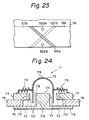
- the conductive portion 57 can be formed as the voice coil of two turns. That is, as shown in Figure 23, a notched portion 521A is formed obliquely in a conductive portion 57A which is formed on the outer periphery of the diaphragm 56, and a notched portion 521B is formed obliquely in a conductive portion 57B which is formed on the inner periphery of the diaphragm 56. Apertures 522A and 522B are formed at positions near the edges of the conductive portions 57A and 57B.
- Conductors are sealed into the apertures 522A and 522B. Due to this, the edge of the conductive portion 57A on the front and the edge of the conductive portion 57B on the rear are respectively electrically connected via the apertures 522A and 522B, thereby obtaining two turns in the conductive portions 57A and 57B,
- the impedance of the loudspeaker is determined by the number of turns of the current feeding coil 55 and the conductive portion 57. If two turns are formed in the conductive portions 57A and 57B as described above, the impedance can more easily be adjusted, and the degree of freedom in the adjustment of the frequency characteristic is improved.
- a coil having a plurality of turns may be formed as the conductive portion 57A on the front and the conductive portion 57B on the rear.
- coils having a plurality of turns may be formed for the conductive portions 57A on the front and the conductive portion 57B on the rear.
- Coils of a plurality of turns are formed for the conductive portion 57A on the front or the conductive portion 57B on the rear and the edge portions of the coils may be electrically connected.
- Figure 24 shows the eighth embodiment of loudspeaker 71 which comprises a diaphragm 72, a damper 79, a current feeding coil 73, a top plate 74, a magnet 75, a yoke plate 76, and a pole piece 711.
- the dome-shaped diaphragm 72 comprises a hemispherical vibrating portion 715 and a conductive portion 78 which is annularly formed at an edge portion 77.
- the diaphragm 72 is supported by the damper 79 so as to vibrate freely with the conductive portion 78 located in a magnetic gap portion 710.
- the conductive portion 78 has a length of L2 and extends a distance l1 below the magnetic gap portion 710, so even if the diaphragm 72 reciprocates considerably in accordance with an induced current, the conductive portion 78 remains in the uniform magnetic field range L1 of the dc magnetic field (L1 ⁇ L2).
- the vibrating portion 715 is formed of an insulating material such as a synthetic resin.
- the whole of the conductive portion 78 is formed of a good conductor like a metal, such as aluminium, beryllium or magnesium, or the whole diaphragm 72 may be also formed of a good conductor as in the foregoing embodiments.
- the magnetic gap portion 710 is annularly formed between the top plate 74 and the pole piece 711 of the yoke plate 76.
- the damper 79 is annular and has a spring characteristic, with its inner peripheral side connected to the periphery of the conductive portion 78 and its outer peripheral side fixed to the top plate 74.
- the current feeding coil 73 faces the conductive portion 78 with a predetermined gap and is coupled thereto by mutual inductance.
- the winding (winding pitch or the like) and the height are similar to those in known coils and, as shown in Figure 25, the height (in the directions U-D) is set to L3, which is equal to the uniform magnetic field range L1, so that the length L2 of the conductive portion 78 is larger than the length L3.
- the current feeding coil 73 is arranged to face the outer or the inner periphery of the conductive portion 78.
- the current feeding coil 73 face the outer periphery, it is fixed to one side edge surface 712 of the top plate 74, and to make it face the inner periphery, it is fixed to the side of the outer periphery 713 of the pole piece 711.
- the current feeding coil 73 may alternatively be provided at both these positions.
- a magnetic circuit is formed through the magnetic gap portion 710 by the top plate 74, the magnet 75, the yoke plate 76, and the pole piece 711. As shown in Figure 24, the magnet 75 is fixed to the outer peripheral portion of the yoke plate 76, and the top plate 74 is fixed to the outer peripheral portion on the magnet 75.
- the dc magnetic field of the uniform magnetic flux distribution is formed in the uniform magnetic field range L1, which is equal to the height (in the directions U and D) of the top plate 74.
- an ac magnetic flux corresponding to the audio signal is developed. Since the annular conductive portion 78 closely interlinks the ac magnetic flux, an induced current corresponding to the audio signal is generated in the conductive portion 78 by mutual inductance, and flows mainly in the uniform magnetic field range, and little outside that range. Since the conductive portion 78 is located in the magnetic gap portion 710, a force which is proportional to the product of the intensity of the dc magnetic field in the magnetic gap portion 710 and the magnitude of the induced current acts on the conductive portion 78, directly driving the diaphragm 72 in the directions U-D and generating the sound wave.
- a force which is proportional to the product of the magnitude of the induced current and the intensity of the dc magnetic field is applied to the conductive portion 78, and, since the induced current accurately corresponds to the audio signal and the intensity of the dc magnetic field does not change, the driving force on the diaphragm 72 corresponds to the audio signal. Therefore, linearity between the audio signal current and the amplitude of the diaphragm 72 is maintained, and no distortion occurs.
- the impedance does not increase and a good frequency characteristic which does not change even in the high-band region is obtained.
- the length of the voice coil wound around the voice coil bobbin is greater than the length of the top plate 74 in the height direction, since in this embodiment no significant induced current flows through the conductive portion 78 outside the uniform magnetic field range L1, electric power is not wasted and the efficiency can be increased.
- the construction of the eighth embodiment is suitable for a loudspeaker for low frequency sound (a woofer) in which the amplitude of the diaphragm 72 is relatively large.
- ninth embodiment differs from the eighth embodiment in that a length L5 of a current feeding coil 720 is set to be larger than a length L4 of a conductive portion 721 in the height direction (the directions U-D).
- the diaphragm 72 Upon operation of the loudspeaker 71, the diaphragm 72 reciprocates in the directions U-D in accordance with the induced current.
- the edge portion 714 of the conductive portion 721 enters the uniform magnetic field range L1, and the length of the overlap portion of the uniform magnetic field range L1 and the conductive portion 721 decreases.
- the current feeding coil 720 is elongated and of length L5
- the ac coupling between the current feeding coil 720 and the conductive portion 721 is held constant. Therefore, the induced current in the conductive portion 721 accurately corresponds to the audio signal. Consequently, as the dc magnetic field does not change the linearity between the audio signal and the amplitude of the diaphragm 22 is maintained and no distortion occurs.
- the weight of the diaphragm 72 in the ninth embodiment can be reduced.
- the construction of the ninth embodiment is suitable for a loudspeaker for high frequency sound (a tweeter) in which the amplitude of the diaphragm 72 is relatively small.
- Figure 27 shows an example in which a current feeding coil 730 is formed of flat wire. That is, in place of ordinary wire of circular cross section, a plurality of flat wires 731 of rectangular cross section are laminated and attached onto the inner periphery of the top plate 74.
- circular wire comes into point contact with the other wire or the top plate 74, while the flat wire 731 comes into area contact, so that the thermal conductivity is good, and the heat generated in the current feeding coil 730 can easily be conducted away.
- Figure 28 shows an example in which a magnetic fluid 740 is arranged in the magnetic gap portion 710.
- the magnetic fluid 740 may, for example, be formed in a gel state by mixing powder of a magnetic material such as iron into an oil.
- the magnetic gap portion 710 By inserting the magnetic fluid 740 into the magnetic gap portion 710, various advantages can be expected. Firstly, when the magnetic fluid 740 is in the magnetic gap portion 710, the magnetic gap portion 710 is equivalently narrowed, so that the magnetic flux density is raised and the efficiency is improved.
- the characteristic of the vibrating system can more easily be controlled, due to the viscous loss of the fluid.
- Figure 29 shows an example of which a heat absorbing material 751 is provided in contact with the rear of a current feeding coil 750 which is long in the height direction (the directions U-D). Since the heat absorbing material 751 is provided in contact with the current feeding coil 750, the whole shape is formed like a ring.
- the whole diaphragm of a conductive polymeric material.
- the conductive portion is formed of a material having a good conductivity by a predetermined chemical method, and freedom in the selection of the material of the diaphragm is increased.
- the tenth embodiment of loudspeaker 41 is shown in Figure 30, and comprises a diaphragm 42, a damper 49, a current feeding coil 43, a top plate 44, a magnet 45, and a yoke plate 46.
- An annular conductive portion 48 is formed at the edge portion 47 of the dome-shaped diaphragm 42.
- the whole diaphragm 42 is made of a polymeric film having a conductive property formed by impregnating carbon or metal powder into a polymeric film. For example, iodine is doped into a base of polyacetylene, thereby providing the conductive property.
- the diaphragm 42 is supported by the damper 49 so as to vibrate freely with the conductive portion 48 located in a magnetic gap 410, which is annularly formed between the top plate 44 and a pole piece 411 of the yoke plate 46.
- the damper 49 has a spring characteristic and is annularly formed.
- the inner peripheral side of the damper 49 is connected to the periphery of the conductive portion 48, and the outer peripheral side is fixed on the top plate 44.
- the position of the current feeding coil 43 and the construction of the magnetic circuit comprising the top plate 44, the magnet 45 and the yoke plate 46 are the same as in other embodiments, and the operation is similar.
- the polymeric film diaphragm 42 Since the polymeric film diaphragm 42 has a relatively large mechanical loss and is light, no resonance peak occurs in the frequency characteristic, and the frequency characteristic of the loudspeaker 41 is flat. Moreover, since the resonance peaks are eliminated, the diaphragm 42 can easily be damped, and the sound quality is improved. In addition, since the diaphragm 42 is light, the response sensitivity of the loudspeaker 41 can be improved. Since the diaphragm 42 is made of a polymeric material, it can extremely easily be moulded, and an excellent frequency characteristic and good sound quality can be obtained.
- the diaphragm 42 and the damper 49 are formed separately, and the damper 49 is connected to the conductive portion 48.
- the damper 49 can be formed integrally with the conductive portion 48. This improves working efficiency on assembling, and reduces working time for repairing.
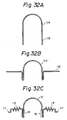
- Figures 31 and 32 show the eleventh embodiment of loudspeaker 11 comprising a diaphragm 12, a current feeding coil 13, a top plate 14, a magnet 15, and a yoke plate 16.
- the dome-shaped diaphragm 12 has at an edge portion 17 an annular conductive portion 18 and a damper 19 which is formed integrally with the conductive portion 18.
- the diaphragm 12 is made of a good conductor of a thin plate shape such as aluminium, beryllium or magnesium.
- the diaphragm 12 is supported by the damper 19 so as to vibrate freely with the conductive portion 18 in a magnetic gap 110.
- the damper 19 has a spring characteristic and is annularly formed around the conductive portion 18, and is fixed onto the top plate 14.
- the magnetic gap 110 is annularly formed between the top plate 14 and a pole piece 111 of the yoke plate 16.
- the current feeding coil 13 electrically couples with the conductive portion 18 by mutual inductance, and faces the conductive portion 18 with a predetermined gap.
- the current feeding coil 13 may face the outer or the inner periphery of the conductive portion 18, or both.
- the current feeding coil 13 in the example shown in Figure 31 is fixed to one side edge surface 112 of the top plate 14, so as to face the outer periphery of the conductive portion 18.
- the current feeding coil 13 may be fixed to the side of an outer periphery 113 of a pole piece 111.
- the top plate 14, the magnet 15, the yoke plate 16, and pole piece 111 form a magnetic circuit.
- the magnet 15 is fixed to the outer peripheral portion of the yoke plate 16, and the top plate 14 is fixed to the outer peripheral position of the magnet 15.
- the magnetic circuit is formed through the magnetic gap 110 along a path from the magnet 15 to the top plate 14, and a path from the magnet 15 to the yoke plate 16 and the pole piece 111.
- an edge portion 115 of a cylindrical member 114 as shown in Figure 32A is turned up to form an annular peripheral edge portion 116 as shown in Figure 32B.
- the damper 19 having a spring characteristic is annularly formed in the peripheral edge portion 116.
- an annular fixing portion 117 for the top plate 14 is also formed.
- the diaphragm 12 can be so formed by pressing or other suitable methods.
- the reciprocating motion of the diaphragm 12 is relatively small.
- the damper 19 has a spring characteristic, it can sufficiently follow the reciprocating motion of the diaphragm 12.
- the diaphragm 12 can easily be attached to and detached from the top plate 14, since the damper 19 is integral.
- Figure 33 shows an example of the formation of the diaphragm 120 in the twelfth embodiment.
- a hemispherical member 121 is shown in Figure 33A, and an annular plate 122 is shown in Figures 33B and 33C, respectively.
- an annular conductive portion 123, an annular damper 124, and an annular fixing portion 125 are formed in the plate 122.
- the diaphragm 120 is formed by connecting the hemispherical member 120 and the plate 122.
- Figure 34 shows how flow of the current induced in the conductive portion 18 to the damper 19 can be reduced by forming an annular notch 131 in a connecting portion 130 of the diaphragm 12 to the damper 19. Since the conductive area is reduced by the notch 131, the resistance is increased, the current flow is decreased, and the efficiency can be raised.
- Each of the foregoing embodiments is intended to improve the response sensitivity and the frequency characteristic of the loudspeaker by suitably selecting the material of the diaphragm, the shape of a conductive portion, or the like.
- Figure 35 shows the thirteenth embodiment of the invention, in which a cylindrical pole piece 62 is formed at the centre of a disc-shaped yoke plate 61.
- a ring-shaped magnet 63 is laminated and fixed onto the yoke plate 61.
- a ring-shaped top plate 64 is laminated and fixed onto the magnet 63.
- An outer magnet type magnetic circuit is formed by the yoke plate 61, the pole piece 62, the magnet 63, and the top plate 64.
- a current feeding coil 65 is wound around the inner periphery of the top plate 64. Lead wires 69A and 69B are led out from the current feeding coil 65. Further, a ring-shaped magnetic material 611 is provided on the inner periphery of the current feeding coil 65. It is also possible to use a member formed by winding a wire in a coil shape as the current feeding coil 65, and to attach the current feeding coil 65 to the top plate 64.
- a dome-shaped diaphragm 66 is integrally formed of a metal such as aluminium.
- a conductive portion 67 is formed in the edge portion of the diaphragm 66.
- the conductive portion 67 operates as a voice coil of one turn.
- a magnetic gap is formed where the outer periphery of the pole piece 62 faces the inner periphery of the top plate 64.
- the conductive portion 67 formed integrally with the diaphragm 66 is located in the magnetic gap.
- the diaphragm 66 is reciprocably supported by a damper 68, which may be formed integrally with the diaphragm 66.
- the loudspeaker is driven by supplying an audio signal to terminals 610A and 610B of the lead wires 69A and 69B. That is, an ac audio signal is supplied to the current feeding coil 65 through the lead wires 69A and 69B. A magnetic flux is generated in the current feeding coil 65 corresponding to the audio signal. The magnetic flux interlinks with the conductive portion 67 which is arranged to face the current feeding coil 65, so an induction current flows through the conductive portion 67. Since the conductive portion 67 is located in the magnetic gap when an induced current flows through the conductive portion 67, a force to move the conductive portion 67 is generated, and the diaphragm 66 is vibrated.
- the ring-shaped magnetic material 611 of a high permeability is provided on the inner periphery of the current feeding coil 65, and as shown in Figure 36, it is desirable to use magnetic material the ends of which are cut or insulated, to prevent the induced current flowing in the ring-shaped magnetic material 611. If a magnetic material of high resistance is used, the induced current can alternatively be dissipated. On the other hand, as shown in Figure 37, it is also possible to use a material in which a number of magnetic members 612 are laminated axially.
- the ring-shaped magnetic material 611 is provided on the inner periphery of the current feeding coil 65. Therefore, the coupling coefficient of the current feeding coil 65 and the conductive portion 67 is increased, and hence the response sensitivity of the loudspeaker is improved and the low frequency reproducing limit decreased.
- the ring-shaped magnetic material 611 may be arranged at any suitable position to raise the coupling coefficient of the current feeding coil 65 and the conductive portion 67.
- the ring-shaped magnetic material 611 may be interposed between the outer periphery of the top plate 64 and the inner periphery of the current feeding coil 65.
- Such an induction type loudspeaker is shown by an equivalent circuit in Figure 41, where R denotes an internal resistance of the current feeding coil 65, L is an inductance of the current feeding coil 65, and M is an ideal transformer comprising the current feeding coil 65 and the conductive portion 67.
- a high-pass filter having a characteristic as shown in Figure 42 is formed by the internal resistance R and the inductance L of the current feeding coil 65.
- a cut-off frequency ⁇ o of the high-pass filter is determined by R/L.
- the low frequency reproducing limit is determined in induction type loudspeaker by the high-pass filter, and in known induction type loudspeakers, the reproduction of low frequencies is impaired.
- the cut-off frequency of the high-pass filter is determined by R/L, it can be lowered by reducing the internal resistance R or increasing the inductance L of the current feeding coil 65. Therefore, consideration is given to lowering the low frequency limit by decreasing the internal resistance R. However, this is difficult to do, so consideration is given to increasing the inductance L by increasing the number of turns of the current feeding coil 65. However, in association with an increase in the inductance L the internal resistance R of the current feeding coil 65 increases.
- the ring-shaped magnetic material 611 is provided on the inner periphery of the current feeding coil 65, and in consequence the inductance L of the current feeding coil 65 rises, so the cut-off frequency of the high-pass filter is lowered and the low frequency reproducing limit can be lowered, improving the low frequency characteristic.
- the low frequency reproducing limit of the induction type loudspeaker can be freely set, so in a loudspeaker system, the network circuit can be simplified.
- the invention also can be applied to cone-type loudspeakers.
- the examples shown in the diagrams relate to outer magnet types in which the magnet is arranged similarly applied to inner magnet types in which the magnet is interchanged with the pole piece.
- the loudspeaker system comprises a loudspeaker 31 for a high frequency band and a loudspeaker 32 for a low frequency band.
- An induction type loudspeaker as described above is used as the loudspeaker 31 for the high frequency band.
- a dynamic type loudspeaker is used as the loudspeaker 32 for the low frequency band.
- an induction type loudspeaker can also be used as the loudspeaker 32 for the low frequency band.
- a network circuit 33 is connected between an output amplifier 34 and the loudspeakers 31 and 32, and comprises a capacitor 35 and a low-pass filter 36.
- the capacitor 35 is arranged at the front stage of the loudspeaker 31, and the low-pass filter 36 is arranged at the front stage of the loudspeaker 32. Connection of the capacitor 35 like this is equivalent to providing a high-pass filter with a steep characteristic of 12 dB/oct at the front stage of the loudspeaker 31. This will now be explained with reference to the Figure 44 which shows an equivalent circuit.
- the input side of the induction type loudspeaker 31 comprises an inductance L3 of the current feeding coil and an internal resistance R3 of the current feeding coil.
- the signal on the input side is transferred to the secondary side, comprising the conductive portion through an ideal transformer M3.
- a high-pass filter of 6 dB/oct as shown in Figure 45 is formed by the inductance L and the internal resistance R of the current feeding coil.
- a cut-off frequency ⁇ o of the high-pass filter is determined by R3/L3.
- a high-pass filter of 6 dB/oct is further formed by a capacitance C3 of the capacitor 35 and the internal resistance R3 of the current feeding coil. Therefore, when the capacitor 35 is so connected, this is equivalent to a high-pass filter of 6 dB/oct comprising the inductance L3 and the internal resistance R3 of the current feeding coil, and a high-pass filter of 6 dB/oct comprising the capacitance C3 of the capacitor 35 and the internal resistance R3 of the current feeding coil connected in cascade.
- variable resistor 331 may also be connected to adjust the cut-off frequency of the high-pass filter comprising the capacitance C3 of the capacitor 35 and the internal resistance R3 of the current feeding coil.
Landscapes
- Physics & Mathematics (AREA)
- Engineering & Computer Science (AREA)
- Acoustics & Sound (AREA)
- Signal Processing (AREA)
- Health & Medical Sciences (AREA)
- Otolaryngology (AREA)
- Audible-Bandwidth Dynamoelectric Transducers Other Than Pickups (AREA)
- Diaphragms For Electromechanical Transducers (AREA)
- Golf Clubs (AREA)
Priority Applications (1)
| Application Number | Priority Date | Filing Date | Title |
|---|---|---|---|
| EP94103841A EP0605400B1 (de) | 1988-04-27 | 1989-04-19 | Dynamischer Lautsprecher |
Applications Claiming Priority (6)
| Application Number | Priority Date | Filing Date | Title |
|---|---|---|---|
| JP63104596A JPH01274600A (ja) | 1988-04-27 | 1988-04-27 | スピーカ |
| JP104596/88 | 1988-04-27 | ||
| JP63120233A JPH0256200A (ja) | 1988-05-17 | 1988-05-17 | スピーカ |
| JP120233/88 | 1988-05-17 | ||
| JP125387/88 | 1988-05-23 | ||
| JP12538788A JP2621348B2 (ja) | 1988-05-23 | 1988-05-23 | スピーカ |
Related Child Applications (2)
| Application Number | Title | Priority Date | Filing Date |
|---|---|---|---|
| EP94103841A Division EP0605400B1 (de) | 1988-04-27 | 1989-04-19 | Dynamischer Lautsprecher |
| EP94103841.6 Division-Into | 1994-03-12 |
Publications (3)
| Publication Number | Publication Date |
|---|---|
| EP0339855A2 true EP0339855A2 (de) | 1989-11-02 |
| EP0339855A3 EP0339855A3 (de) | 1992-03-11 |
| EP0339855B1 EP0339855B1 (de) | 1995-09-20 |
Family
ID=27310261
Family Applications (2)
| Application Number | Title | Priority Date | Filing Date |
|---|---|---|---|
| EP89303854A Expired - Lifetime EP0339855B1 (de) | 1988-04-27 | 1989-04-19 | Elektrodynamischer Lautsprecher |
| EP94103841A Expired - Lifetime EP0605400B1 (de) | 1988-04-27 | 1989-04-19 | Dynamischer Lautsprecher |
Family Applications After (1)
| Application Number | Title | Priority Date | Filing Date |
|---|---|---|---|
| EP94103841A Expired - Lifetime EP0605400B1 (de) | 1988-04-27 | 1989-04-19 | Dynamischer Lautsprecher |
Country Status (7)
| Country | Link |
|---|---|
| US (1) | US5062140A (de) |
| EP (2) | EP0339855B1 (de) |
| KR (1) | KR0129547B1 (de) |
| AT (2) | ATE128312T1 (de) |
| CA (1) | CA1313254C (de) |
| DE (2) | DE68928871T2 (de) |
| MY (1) | MY103881A (de) |
Cited By (9)
| Publication number | Priority date | Publication date | Assignee | Title |
|---|---|---|---|---|
| EP0339820A3 (de) * | 1988-04-26 | 1991-03-20 | Saad Gabr | Elektromagnetischer Wandler |
| EP0453130A3 (en) * | 1990-04-18 | 1992-07-08 | Klipsch And Associates Inc. | Inductively activated loudspeaker with conductive tube |
| EP0685982A3 (de) * | 1994-06-01 | 1996-06-05 | Nokia Technology Gmbh | Lautsprecher. |
| GB2333928A (en) * | 1995-02-17 | 1999-08-04 | Citizen Electronics | A surface-mounted electromagnetic sound generator |
| EP1480490A1 (de) * | 2003-05-20 | 2004-11-24 | Pioneer Corporation | Magnesiumlautsprechermembran, Verfahren zu deren Hestellung und Lautsprecher mit einer solchen Membran |
| EP1599066A3 (de) * | 2004-05-19 | 2006-12-06 | Pioneer Corporation | Magnesium-Membran mit integrierter Schwingspule,Verfahren zu deren Herstellung und Lautsprechergerät mit Anwendung einer solchen Membran |
| FR3017220A1 (fr) * | 2014-01-31 | 2015-08-07 | Dav | Dispositif de retour sensitif pour vehicule automobile et procede de generation d'un retour sensitif |
| CN109525924A (zh) * | 2017-09-19 | 2019-03-26 | 惠州超声音响有限公司 | 具有开放式感应线圈的扬声器 |
| CN110049413A (zh) * | 2019-05-10 | 2019-07-23 | 广东朝阳电子科技股份有限公司 | 音质改良型双磁路双振膜的振动动圈复合喇叭 |
Families Citing this family (30)
| Publication number | Priority date | Publication date | Assignee | Title |
|---|---|---|---|---|
| US6222931B1 (en) * | 1989-05-11 | 2001-04-24 | Outline Snc | High power acoustical transducer |
| US5438627A (en) * | 1992-12-30 | 1995-08-01 | At&T Corp. | Reactance-mass actuator |
| DE4317775C2 (de) * | 1993-02-03 | 1995-02-02 | Foster Electric Co Ltd | Lautsprecher |
| US5381483A (en) * | 1993-04-05 | 1995-01-10 | Commonwealth Of Puerto Rico | Minimal inductance electrodynamic transducer |
| US5461677A (en) * | 1993-09-16 | 1995-10-24 | Ferrofluidics Corporation | Loudspeaker |
| ATE205040T1 (de) * | 1994-06-01 | 2001-09-15 | Harman Audio Electronic Sys | Lautsprecher |
| DE19610997B4 (de) * | 1996-03-21 | 2006-07-13 | Sennheiser Electronic Gmbh & Co. Kg | Elektrodynamischer Schallwandler mit Magnetspaltenabdichtung und Hörhilfe |
| JPH1051888A (ja) * | 1996-05-28 | 1998-02-20 | Sony Corp | スピーカ装置および音声再生システム |
| US6394224B1 (en) * | 2000-03-30 | 2002-05-28 | Chun-I Liu | Structure of speaker |
| US6373957B1 (en) | 2001-05-14 | 2002-04-16 | Harman International Industries, Incorporated | Loudspeaker structure |
| ATE411561T1 (de) | 2001-06-28 | 2008-10-15 | Nokia Corp | Verfahren zum ermöglichen von übertragung zwischen prozessen und verarbeitungssystem unter verwendung desselben |
| JP2004261684A (ja) * | 2003-02-28 | 2004-09-24 | Citizen Electronics Co Ltd | 振動体及びその製造方法 |
| US7177439B2 (en) * | 2003-03-06 | 2007-02-13 | Peavey Electronics Corporation | Methods and apparatus for dissipating heat in a voice coil |
| FR2854021B1 (fr) * | 2003-04-16 | 2006-03-31 | Focal Jmlab | Transducteur acoustiques en beryllium pur a radiation directe, a membrane de forme concave, pour applications audio notamment pour enceintes acoustiques |
| JP2005151253A (ja) * | 2003-11-17 | 2005-06-09 | Sony Corp | スピーカ装置 |
| JP3981926B2 (ja) * | 2003-11-17 | 2007-09-26 | ソニー株式会社 | スピーカ装置 |
| JP3797561B2 (ja) * | 2003-11-18 | 2006-07-19 | ソニー株式会社 | スピーカ装置 |
| JP4573543B2 (ja) * | 2004-03-02 | 2010-11-04 | 株式会社オーディオテクニカ | 可動リボン型マイクロホン |
| KR100799008B1 (ko) * | 2004-03-31 | 2008-01-28 | 마쯔시다덴기산교 가부시키가이샤 | 스피커와, 이를 이용한 모듈, 전자 기기 및 장치, 스피커의제조 방법 |
| US8009857B2 (en) * | 2007-02-15 | 2011-08-30 | Wisdom Audio Corp. | Induction motor for loudspeaker |
| US20100278361A1 (en) * | 2007-06-20 | 2010-11-04 | Hpv Technologies, Inc. | Configurations And Methods For Broadband Planar Magnetic Induction Transducers |
| CN102197661B (zh) * | 2008-10-27 | 2013-12-11 | 松下电器产业株式会社 | 扬声器、扬声器的制造方法及扬声器制造的夹具 |
| KR101096546B1 (ko) * | 2009-11-10 | 2011-12-22 | 주식회사 비에스이 | 정전형 스피커 |
| KR101029527B1 (ko) * | 2010-06-28 | 2011-04-18 | 일진경금속 주식회사 | 보빈 일체형 마그네슘 진동판의 제조 방법 |
| US8374380B2 (en) * | 2011-04-08 | 2013-02-12 | Zylux Acoustic Corporation | Speaker voice coil structure having at least three coils |
| US10595131B2 (en) * | 2015-09-21 | 2020-03-17 | Apple Inc. | Audio speaker having an electrical path through a magnet assembly |
| US9980050B2 (en) * | 2015-09-29 | 2018-05-22 | Coleridge Design Associates Llc | System and method for a loudspeaker with a diaphragm |
| CN108430004B (zh) * | 2018-04-16 | 2020-09-25 | 维沃移动通信有限公司 | 一种扬声器振幅调节装置、调节方法及移动终端 |
| CA3127120A1 (fr) | 2019-02-06 | 2020-08-13 | OLTRAMARE, Michel | Systeme de refroidissement de la bobine fixe d'un moteur inductif |
| US12513469B2 (en) | 2020-04-08 | 2025-12-30 | Michel OLTRAMARE | Dual axial magnetic flux induction speaker |
Family Cites Families (21)
| Publication number | Priority date | Publication date | Assignee | Title |
|---|---|---|---|---|
| US1570287A (en) * | 1924-01-25 | 1926-01-19 | Siemens Ag | Telephone |
| US2003901A (en) * | 1931-05-19 | 1935-06-04 | Pittsburgh Equitable Meter Co | Piston meter |
| US2492255A (en) * | 1944-12-26 | 1949-12-27 | John O Angehrn | Sealed-coil type vibratory magnet loudspeaker |
| US2494918A (en) * | 1946-09-17 | 1950-01-17 | Volkers & Schaffer Inc | Inductively energized electro-dynamic loud-speaker |
| NL104049C (de) * | 1954-10-28 | |||
| US3586792A (en) * | 1970-02-24 | 1971-06-22 | Int Standard Electric Corp | Method for assembling electro-acoustical transducer diaphragm assemblies |
| US3838216A (en) * | 1972-02-23 | 1974-09-24 | W Watkins | Device to effectively eliminate the motion induced back emf in a loudspeaker system in the region of fundamental acoustic resonance |
| JPS5324338B2 (de) * | 1974-01-29 | 1978-07-20 | ||
| JPS50105438A (de) * | 1974-01-30 | 1975-08-20 | ||
| FR2382822B1 (fr) * | 1977-03-01 | 1985-08-30 | Seas Fabrikker As | Dispositif pour haut-parleur electrodynamique |
| JPS568997A (en) * | 1979-07-05 | 1981-01-29 | Kuwata Momoyo | Loudspeaker |
| JPS5627039A (en) * | 1979-08-10 | 1981-03-16 | Nissan Motor Co Ltd | Electronic control type fuel-jetting device for internal- combustion engine |
| JPS57131200A (en) * | 1980-02-26 | 1982-08-13 | Koji Sakai | Electromagnetic driving system |
| DE3027586C2 (de) * | 1980-07-21 | 1985-07-18 | Sennheiser Electronic Kg, 3002 Wedemark | Elektroakustischer Wandler |
| JPS5728497A (en) * | 1980-07-29 | 1982-02-16 | Mitsubishi Electric Corp | Magnetic circuit for speaker |
| GB2082418A (en) * | 1980-08-15 | 1982-03-03 | Rola Celestion Ltd | Multi-way loudspeaker system |
| JPS5932292A (ja) * | 1982-08-16 | 1984-02-21 | Hitachi Ltd | スピ−カ |
| JPS5936689U (ja) * | 1982-08-31 | 1984-03-07 | パイオニア株式会社 | スピ−カ装置 |
| FR2556164B1 (fr) * | 1983-12-03 | 1994-02-25 | Pioneer Electronic Corp | Haut-parleur |
| US4709392A (en) * | 1984-03-08 | 1987-11-24 | Onkyo Kabushiki Kaisha | Dome speaker with a diaphragm having at least one elongated cut-out portion |
| JPS61184094A (ja) * | 1985-02-08 | 1986-08-16 | Hitachi Ltd | スピ−カ |
-
1989
- 1989-04-18 US US07/340,034 patent/US5062140A/en not_active Expired - Lifetime
- 1989-04-19 AT AT89303854T patent/ATE128312T1/de not_active IP Right Cessation
- 1989-04-19 DE DE68928871T patent/DE68928871T2/de not_active Expired - Lifetime
- 1989-04-19 AT AT94103841T patent/ATE174182T1/de not_active IP Right Cessation
- 1989-04-19 EP EP89303854A patent/EP0339855B1/de not_active Expired - Lifetime
- 1989-04-19 DE DE68924298T patent/DE68924298T2/de not_active Expired - Lifetime
- 1989-04-19 EP EP94103841A patent/EP0605400B1/de not_active Expired - Lifetime
- 1989-04-21 MY MYPI89000515A patent/MY103881A/en unknown
- 1989-04-21 CA CA000597500A patent/CA1313254C/en not_active Expired - Lifetime
- 1989-04-26 KR KR1019890005483A patent/KR0129547B1/ko not_active Expired - Fee Related
Cited By (11)
| Publication number | Priority date | Publication date | Assignee | Title |
|---|---|---|---|---|
| EP0339820A3 (de) * | 1988-04-26 | 1991-03-20 | Saad Gabr | Elektromagnetischer Wandler |
| EP0453130A3 (en) * | 1990-04-18 | 1992-07-08 | Klipsch And Associates Inc. | Inductively activated loudspeaker with conductive tube |
| EP0685982A3 (de) * | 1994-06-01 | 1996-06-05 | Nokia Technology Gmbh | Lautsprecher. |
| GB2333928A (en) * | 1995-02-17 | 1999-08-04 | Citizen Electronics | A surface-mounted electromagnetic sound generator |
| GB2333928B (en) * | 1995-02-17 | 1999-09-15 | Citizen Electronics | Surface-mounted electromagnetic sound generator |
| EP1480490A1 (de) * | 2003-05-20 | 2004-11-24 | Pioneer Corporation | Magnesiumlautsprechermembran, Verfahren zu deren Hestellung und Lautsprecher mit einer solchen Membran |
| US7308750B2 (en) | 2003-05-20 | 2007-12-18 | Pioneer Corporation | Method of manufacturing a magnesium diaphragm |
| EP1599066A3 (de) * | 2004-05-19 | 2006-12-06 | Pioneer Corporation | Magnesium-Membran mit integrierter Schwingspule,Verfahren zu deren Herstellung und Lautsprechergerät mit Anwendung einer solchen Membran |
| FR3017220A1 (fr) * | 2014-01-31 | 2015-08-07 | Dav | Dispositif de retour sensitif pour vehicule automobile et procede de generation d'un retour sensitif |
| CN109525924A (zh) * | 2017-09-19 | 2019-03-26 | 惠州超声音响有限公司 | 具有开放式感应线圈的扬声器 |
| CN110049413A (zh) * | 2019-05-10 | 2019-07-23 | 广东朝阳电子科技股份有限公司 | 音质改良型双磁路双振膜的振动动圈复合喇叭 |
Also Published As
| Publication number | Publication date |
|---|---|
| EP0605400B1 (de) | 1998-12-02 |
| ATE174182T1 (de) | 1998-12-15 |
| DE68924298T2 (de) | 1996-03-21 |
| US5062140A (en) | 1991-10-29 |
| EP0339855A3 (de) | 1992-03-11 |
| EP0605400A1 (de) | 1994-07-06 |
| KR0129547B1 (ko) | 1998-04-14 |
| DE68924298D1 (de) | 1995-10-26 |
| DE68928871D1 (de) | 1999-01-14 |
| CA1313254C (en) | 1993-01-26 |
| EP0339855B1 (de) | 1995-09-20 |
| MY103881A (en) | 1993-09-30 |
| KR900017433A (ko) | 1990-11-16 |
| ATE128312T1 (de) | 1995-10-15 |
| DE68928871T2 (de) | 1999-06-02 |
Similar Documents
| Publication | Publication Date | Title |
|---|---|---|
| EP0339855A2 (de) | Elektrodynamischer Lautsprecher | |
| CN108966095B (zh) | 扬声器单元及扬声器装置 | |
| JP2543765B2 (ja) | 電気音響変換器およびスピ―カ | |
| US6993147B2 (en) | Low cost broad range loudspeaker and system | |
| EP1247424A1 (de) | Billiger breitbereichslautsprecher und system | |
| US4295006A (en) | Speaker system | |
| US9282410B2 (en) | Transducer motor structure with enhanced flux | |
| US5537481A (en) | Horn driver | |
| US4225756A (en) | Broad band dynamic loudspeaker | |
| US4225757A (en) | Broad band dynamic loudspeaker | |
| US7873180B2 (en) | Voice coil actuator | |
| EP1471768A1 (de) | Lautsprecher für die wiedergabe im superhohen frequenzbereich | |
| US7177439B2 (en) | Methods and apparatus for dissipating heat in a voice coil | |
| JP4015565B2 (ja) | 超高域再生用スピーカ | |
| JP2996842B2 (ja) | スピーカ | |
| JP7245958B2 (ja) | ラウドスピーカ | |
| EP3952340A1 (de) | Anzeigevorrichtung | |
| JPH0984187A (ja) | スピーカ | |
| EP4589993A1 (de) | Mehrspaltiger magnetischer motor zur verwendung in lautsprechern | |
| JP2000152363A (ja) | 動電形スピーカユニット | |
| JP2737273B2 (ja) | 動電型スピーカ | |
| JP4630319B2 (ja) | ホーンスピーカ | |
| RU102284U1 (ru) | Широкополосный электродинамический громкоговоритель | |
| KR101558089B1 (ko) | 마그네슘 진동판 모듈 및 이를 이용한 장방형 스피커 | |
| KR200279585Y1 (ko) | 스피커 |
Legal Events
| Date | Code | Title | Description |
|---|---|---|---|
| PUAI | Public reference made under article 153(3) epc to a published international application that has entered the european phase |
Free format text: ORIGINAL CODE: 0009012 |
|
| AK | Designated contracting states |
Kind code of ref document: A2 Designated state(s): AT DE FR GB IT NL |
|
| PUAL | Search report despatched |
Free format text: ORIGINAL CODE: 0009013 |
|
| AK | Designated contracting states |
Kind code of ref document: A3 Designated state(s): AT DE FR GB IT NL |
|
| 17P | Request for examination filed |
Effective date: 19920808 |
|
| 17Q | First examination report despatched |
Effective date: 19930507 |
|
| GRAA | (expected) grant |
Free format text: ORIGINAL CODE: 0009210 |
|
| AK | Designated contracting states |
Kind code of ref document: B1 Designated state(s): AT DE FR GB IT NL |
|
| REF | Corresponds to: |
Ref document number: 128312 Country of ref document: AT Date of ref document: 19951015 Kind code of ref document: T |
|
| XX | Miscellaneous (additional remarks) |
Free format text: TEILANMELDUNG 94103841.6 EINGEREICHT AM 19/04/89. |
|
| REF | Corresponds to: |
Ref document number: 68924298 Country of ref document: DE Date of ref document: 19951026 |
|
| ITF | It: translation for a ep patent filed | ||
| ET | Fr: translation filed | ||
| PLBE | No opposition filed within time limit |
Free format text: ORIGINAL CODE: 0009261 |
|
| STAA | Information on the status of an ep patent application or granted ep patent |
Free format text: STATUS: NO OPPOSITION FILED WITHIN TIME LIMIT |
|
| 26N | No opposition filed | ||
| REG | Reference to a national code |
Ref country code: GB Ref legal event code: IF02 |
|
| PGFP | Annual fee paid to national office [announced via postgrant information from national office to epo] |
Ref country code: DE Payment date: 20080424 Year of fee payment: 20 Ref country code: FR Payment date: 20080312 Year of fee payment: 20 |
|
| PGFP | Annual fee paid to national office [announced via postgrant information from national office to epo] |
Ref country code: AT Payment date: 20080410 Year of fee payment: 20 |
|
| PGFP | Annual fee paid to national office [announced via postgrant information from national office to epo] |
Ref country code: IT Payment date: 20080428 Year of fee payment: 20 |
|
| PGFP | Annual fee paid to national office [announced via postgrant information from national office to epo] |
Ref country code: NL Payment date: 20080403 Year of fee payment: 20 |
|
| PGFP | Annual fee paid to national office [announced via postgrant information from national office to epo] |
Ref country code: GB Payment date: 20080423 Year of fee payment: 20 |
|
| REG | Reference to a national code |
Ref country code: GB Ref legal event code: PE20 Expiry date: 20090418 |
|
| PG25 | Lapsed in a contracting state [announced via postgrant information from national office to epo] |
Ref country code: NL Free format text: LAPSE BECAUSE OF EXPIRATION OF PROTECTION Effective date: 20090419 |
|
| NLV7 | Nl: ceased due to reaching the maximum lifetime of a patent |
Effective date: 20090419 |
|
| PG25 | Lapsed in a contracting state [announced via postgrant information from national office to epo] |
Ref country code: GB Free format text: LAPSE BECAUSE OF EXPIRATION OF PROTECTION Effective date: 20090418 |