EP0339441B1 - Kugelraste - Google Patents
Kugelraste Download PDFInfo
- Publication number
- EP0339441B1 EP0339441B1 EP89106961A EP89106961A EP0339441B1 EP 0339441 B1 EP0339441 B1 EP 0339441B1 EP 89106961 A EP89106961 A EP 89106961A EP 89106961 A EP89106961 A EP 89106961A EP 0339441 B1 EP0339441 B1 EP 0339441B1
- Authority
- EP
- European Patent Office
- Prior art keywords
- ball
- retainer
- shell
- several
- guiding portion
- Prior art date
- Legal status (The legal status is an assumption and is not a legal conclusion. Google has not performed a legal analysis and makes no representation as to the accuracy of the status listed.)
- Expired - Lifetime
Links
- 238000005096 rolling process Methods 0.000 claims description 48
- 239000000463 material Substances 0.000 claims description 10
- 238000003466 welding Methods 0.000 claims description 9
- 239000002184 metal Substances 0.000 claims description 8
- 238000003780 insertion Methods 0.000 claims description 7
- 230000037431 insertion Effects 0.000 claims description 7
- 238000000034 method Methods 0.000 claims description 3
- 239000007779 soft material Substances 0.000 claims description 3
- 210000001331 nose Anatomy 0.000 claims 2
- 239000011324 bead Substances 0.000 claims 1
- 210000003128 head Anatomy 0.000 claims 1
- 230000000717 retained effect Effects 0.000 claims 1
- 230000006835 compression Effects 0.000 description 12
- 238000007906 compression Methods 0.000 description 12
- 238000004519 manufacturing process Methods 0.000 description 10
- 238000006073 displacement reaction Methods 0.000 description 7
- POIUWJQBRNEFGX-XAMSXPGMSA-N cathelicidin Chemical compound C([C@@H](C(=O)N[C@@H](CCCNC(N)=N)C(=O)N[C@@H](CCCCN)C(=O)N[C@@H](CO)C(=O)N[C@@H](CCCCN)C(=O)N[C@@H](CCC(O)=O)C(=O)N[C@@H](CCCCN)C(=O)N[C@@H]([C@@H](C)CC)C(=O)NCC(=O)N[C@@H](CCCCN)C(=O)N[C@@H](CCC(O)=O)C(=O)N[C@@H](CC=1C=CC=CC=1)C(=O)N[C@@H](CCCCN)C(=O)N[C@@H](CCCNC(N)=N)C(=O)N[C@@H]([C@@H](C)CC)C(=O)N[C@@H](C(C)C)C(=O)N[C@@H](CCC(N)=O)C(=O)N[C@@H](CCCNC(N)=N)C(=O)N[C@@H]([C@@H](C)CC)C(=O)N[C@@H](CCCCN)C(=O)N[C@@H](CC(O)=O)C(=O)N[C@@H](CC=1C=CC=CC=1)C(=O)N[C@@H](CC(C)C)C(=O)N[C@@H](CCCNC(N)=N)C(=O)N[C@@H](CC(N)=O)C(=O)N[C@@H](CC(C)C)C(=O)N[C@@H](C(C)C)C(=O)N1[C@@H](CCC1)C(=O)N[C@@H](CCCNC(N)=N)C(=O)N[C@@H]([C@@H](C)O)C(=O)N[C@@H](CCC(O)=O)C(=O)N[C@@H](CO)C(O)=O)NC(=O)[C@H](CC=1C=CC=CC=1)NC(=O)[C@H](CC(O)=O)NC(=O)CNC(=O)[C@H](CC(C)C)NC(=O)[C@@H](N)CC(C)C)C1=CC=CC=C1 POIUWJQBRNEFGX-XAMSXPGMSA-N 0.000 description 2
- 230000002028 premature Effects 0.000 description 2
- 230000015572 biosynthetic process Effects 0.000 description 1
- 210000001520 comb Anatomy 0.000 description 1
- 238000005520 cutting process Methods 0.000 description 1
- 230000009969 flowable effect Effects 0.000 description 1
- 230000005484 gravity Effects 0.000 description 1
- 230000005764 inhibitory process Effects 0.000 description 1
- 230000003993 interaction Effects 0.000 description 1
- 230000013011 mating Effects 0.000 description 1
- 238000000465 moulding Methods 0.000 description 1
- 230000000149 penetrating effect Effects 0.000 description 1
- 239000011343 solid material Substances 0.000 description 1
- 125000006850 spacer group Chemical group 0.000 description 1
- 238000003860 storage Methods 0.000 description 1
- 238000004381 surface treatment Methods 0.000 description 1
- 239000000725 suspension Substances 0.000 description 1
- 239000002699 waste material Substances 0.000 description 1
Images


Classifications
-
- G—PHYSICS
- G05—CONTROLLING; REGULATING
- G05G—CONTROL DEVICES OR SYSTEMS INSOFAR AS CHARACTERISED BY MECHANICAL FEATURES ONLY
- G05G5/00—Means for preventing, limiting or returning the movements of parts of a control mechanism, e.g. locking controlling member
- G05G5/06—Means for preventing, limiting or returning the movements of parts of a control mechanism, e.g. locking controlling member for holding members in one or a limited number of definite positions only
- G05G5/065—Means for preventing, limiting or returning the movements of parts of a control mechanism, e.g. locking controlling member for holding members in one or a limited number of definite positions only using a spring-loaded ball
-
- F—MECHANICAL ENGINEERING; LIGHTING; HEATING; WEAPONS; BLASTING
- F16—ENGINEERING ELEMENTS AND UNITS; GENERAL MEASURES FOR PRODUCING AND MAINTAINING EFFECTIVE FUNCTIONING OF MACHINES OR INSTALLATIONS; THERMAL INSULATION IN GENERAL
- F16C—SHAFTS; FLEXIBLE SHAFTS; ELEMENTS OR CRANKSHAFT MECHANISMS; ROTARY BODIES OTHER THAN GEARING ELEMENTS; BEARINGS
- F16C2370/00—Apparatus relating to physics, e.g. instruments
-
- F—MECHANICAL ENGINEERING; LIGHTING; HEATING; WEAPONS; BLASTING
- F16—ENGINEERING ELEMENTS AND UNITS; GENERAL MEASURES FOR PRODUCING AND MAINTAINING EFFECTIVE FUNCTIONING OF MACHINES OR INSTALLATIONS; THERMAL INSULATION IN GENERAL
- F16C—SHAFTS; FLEXIBLE SHAFTS; ELEMENTS OR CRANKSHAFT MECHANISMS; ROTARY BODIES OTHER THAN GEARING ELEMENTS; BEARINGS
- F16C29/00—Bearings for parts moving only linearly
- F16C29/04—Ball or roller bearings
- F16C29/045—Ball or roller bearings having rolling elements journaled in one of the moving parts
- F16C29/046—Ball or roller bearings having rolling elements journaled in one of the moving parts with balls journaled in pockets
-
- F—MECHANICAL ENGINEERING; LIGHTING; HEATING; WEAPONS; BLASTING
- F16—ENGINEERING ELEMENTS AND UNITS; GENERAL MEASURES FOR PRODUCING AND MAINTAINING EFFECTIVE FUNCTIONING OF MACHINES OR INSTALLATIONS; THERMAL INSULATION IN GENERAL
- F16C—SHAFTS; FLEXIBLE SHAFTS; ELEMENTS OR CRANKSHAFT MECHANISMS; ROTARY BODIES OTHER THAN GEARING ELEMENTS; BEARINGS
- F16C3/00—Shafts; Axles; Cranks; Eccentrics
- F16C3/02—Shafts; Axles
- F16C3/03—Shafts; Axles telescopic
- F16C3/035—Shafts; Axles telescopic with built-in bearings
-
- F—MECHANICAL ENGINEERING; LIGHTING; HEATING; WEAPONS; BLASTING
- F16—ENGINEERING ELEMENTS AND UNITS; GENERAL MEASURES FOR PRODUCING AND MAINTAINING EFFECTIVE FUNCTIONING OF MACHINES OR INSTALLATIONS; THERMAL INSULATION IN GENERAL
- F16H—GEARING
- F16H63/00—Control outputs from the control unit to change-speed- or reversing-gearings for conveying rotary motion or to other devices than the final output mechanism
- F16H63/02—Final output mechanisms therefor; Actuating means for the final output mechanisms
- F16H63/30—Constructional features of the final output mechanisms
- F16H63/38—Detents
-
- Y—GENERAL TAGGING OF NEW TECHNOLOGICAL DEVELOPMENTS; GENERAL TAGGING OF CROSS-SECTIONAL TECHNOLOGIES SPANNING OVER SEVERAL SECTIONS OF THE IPC; TECHNICAL SUBJECTS COVERED BY FORMER USPC CROSS-REFERENCE ART COLLECTIONS [XRACs] AND DIGESTS
- Y10—TECHNICAL SUBJECTS COVERED BY FORMER USPC
- Y10T—TECHNICAL SUBJECTS COVERED BY FORMER US CLASSIFICATION
- Y10T403/00—Joints and connections
- Y10T403/60—Biased catch or latch
- Y10T403/602—Biased catch or latch by separate spring
- Y10T403/604—Radially sliding catch
-
- Y—GENERAL TAGGING OF NEW TECHNOLOGICAL DEVELOPMENTS; GENERAL TAGGING OF CROSS-SECTIONAL TECHNOLOGIES SPANNING OVER SEVERAL SECTIONS OF THE IPC; TECHNICAL SUBJECTS COVERED BY FORMER USPC CROSS-REFERENCE ART COLLECTIONS [XRACs] AND DIGESTS
- Y10—TECHNICAL SUBJECTS COVERED BY FORMER USPC
- Y10T—TECHNICAL SUBJECTS COVERED BY FORMER US CLASSIFICATION
- Y10T74/00—Machine element or mechanism
- Y10T74/20—Control lever and linkage systems
- Y10T74/20012—Multiple controlled elements
- Y10T74/20018—Transmission control
- Y10T74/20177—Particular element [e.g., shift fork, template, etc.]
-
- Y—GENERAL TAGGING OF NEW TECHNOLOGICAL DEVELOPMENTS; GENERAL TAGGING OF CROSS-SECTIONAL TECHNOLOGIES SPANNING OVER SEVERAL SECTIONS OF THE IPC; TECHNICAL SUBJECTS COVERED BY FORMER USPC CROSS-REFERENCE ART COLLECTIONS [XRACs] AND DIGESTS
- Y10—TECHNICAL SUBJECTS COVERED BY FORMER USPC
- Y10T—TECHNICAL SUBJECTS COVERED BY FORMER US CLASSIFICATION
- Y10T74/00—Machine element or mechanism
- Y10T74/20—Control lever and linkage systems
- Y10T74/20576—Elements
- Y10T74/20582—Levers
- Y10T74/2063—Stops
Definitions
- the invention relates to a ball catch, in particular for the shift shaft of motor vehicles, in which the catch ball rests against the shift shaft under the action of a compression spring guided in a bushing and the catch ball is guided in parallel grooves on the shift shaft and from one groove to the other, rolling over the intermediate combs, can snap in, the locking ball is mounted in a spherical half-shell on small bearing balls and the compression spring acts on the spherical half-shell, which is provided on its outer edge with an expansion of the diameter that allows free movement of the small bearing balls and in its center is provided with a recess which allows free movement of the small bearing balls and the ball half-shell sits on a guide part, which in turn has a seat and a guide for the Compression spring and is axially displaceably guided in a bushing with rolling elements.
- rollers or balls which are to be used as supports for easily displaceable furniture. These running balls are mounted in a comparable manner, the ball half-shell being guided in a bush and being under spring pressure.
- This resilient mounting is intended only for the fact that when the furniture is loaded, for example in a chair on which a person sits, the suspension yields and the furniture leg then stands directly on the support - in other words, the "roller” is sunk - So that a displacement of the furniture in the loaded state is no longer possible.
- Such rollers in which the spherical half-shell with its short guide part consists of a deep-drawn part made of sheet metal are only suitable for vertical loads (US Pat. No. 3,557,401).
- a ball catch of the generic type is characterized in that the spherical half-shell and the guide parts are formed as deep-drawn parts made of sheet metal and are firmly connected to one another by means of welding or riveting.
- both the spherical half-shell and the guide part are formed as parts, the largest cross-section of which lies on their open side
- the invention is based on the knowledge that these two parts can each be designed as deep-drawn parts made of sheet metal .
- These parts were previously made of solid material and were therefore manufactured at high cost, and manufacturing-related tolerances also had to be accepted.
- significantly lower tolerances can be maintained, so that the two deep-drawn parts, which each serve as treads for rolling bearing bodies, are particularly well suited for mating with rolling bodies and thus for the formation of rolling bearings if very low tolerances are observed .
- the two deep-drawn parts, the spherical half-shell and the guide part are firmly connected to one another by means of welding or riveting.
- the central spherical cap is produced as a recess in the ball bed by the pressure point of the connecting spot welding (or riveting) between the spherical half-shell and the guide part.
- the guide part is expediently cup-shaped, and the base can be arched for flat contact with the spherical half-shell.
- a ball catch of the generic type is characterized in that the guide part is provided with at least one axially parallel slot in its cylindrical wall and is expanded in such a way that it presses the surrounding rolling elements against the inside of the bush without play.
- This resilient design of the guide part is easy to manufacture on the one hand, on the other hand it is caused by the fact that the rolling elements are mounted on their tracks between the outer surface of the guide part and the inner surface of the bushing without play. As a result, the guide part and thus the entire ball catch is optimally guided. In the case of rolling element bearings, a certain, albeit very slight, clearance is generally required so that the individual parts can be put together and the rolling elements can roll in the intended manner. Due to the manufacturing process, this absolutely necessary game is provided with certain tolerances, so that, for example, if the tolerances are paired unfavorably, the game is relatively large and, as a result, "slippage" is the result.
- the spherical half-shells and the guide part can be firmly connected to one another by means of a rivet or screw.
- the rivet or screw head, lying in the spherical half-shell can be designed as a central spherical cap in the ball bed.
- the inside of the bottom of the guide part can be designed with a protruding shape as a guide for the compression spring.
- a cylinder part can be arranged as a guide for the compression spring, in particular on the inside of the bottom of the guide part.
- the cylinder part placed on the inside of the base can form the head of the rivet or screw, which establishes the fixed connection between the spherical half-shell and the guide part.
- a recess can be formed in the wall as a bearing for the compression spring.
- the upper end of the ball bed is formed by a retaining ring as a snap ring which is in an inner groove immediately below the Edge of the spherical half-shell, however, is inserted outside the center of the locking ball - at a distance from the uppermost balls of the ball bed - and its inner free diameter is less than the largest diameter of the locking ball.
- a retaining ring for the latching ball can be held on the upper edge of the spherical half-shell by an inward edge flange on the shell.
- the non-hardenable, soft material of the retaining ring is only slightly smaller than the diameter of the locking ball in order to enable the locking ball to snap through when inserted.
- the retaining ring, the free inner diameter of which is at least equal to the locking ball diameter, can be provided with at least three inwardly projecting lugs whose end faces lie on a smaller diameter than that of the locking ball.
- the retaining ring can also have a conical shape, so that its free inside diameter corresponds to the diameter of the locking ball and is pressed into a flat shape after the insertion of the locking ball while reducing its inside diameter.
- the retaining ring consists of hardenable material, it can be provided with at least two opposing snap-in and retaining lugs for the locking ball. In the latter case, it makes sense for the spherical half-shell, retaining ring and guide part to be made of hardenable material and to be hardened together, that is to say after they have been assembled or assembled.
- the retaining ring on the upper edge of the spherical half-shell not only prevents the small balls of the spherical bed from falling out of the spherical half-shell, but the arrangement of the retaining ring at a distance from the uppermost edge of the spherical bed ensures that there is sufficient space for movement the locking ball, so that rolling on the ball bed and the resulting flowing movements of the ball bed, there is always enough space so that the small balls of the ball bed can dodge to add to those places where they come back into engagement with the locking ball, causing a jam small balls of the ball bed is effectively avoided, and therefore only partially rubbing the locking ball on the ball bed is avoided or cannot occur.
- the various designs of the retaining ring described above ensure that the locking ball is guided securely in the ball half-shell and cannot fall out, the assembly, that is to say the insertion of the locking ball into the ball half-shell, being considerably simplified and facilitated.
- proposals have been made for using hardened parts as well as a non-hardened or non-hardenable retaining ring, so that the overall structure has to be adapted to the respective optimal conditions.
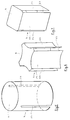
- the manufacture is very simple if the guide part consists of deep-drawn material and, for example, two axially parallel slots lie opposite one another.
- the guide part can then be deep drawn from an approximately strip-shaped raw sheet metal part, the two slots being formed by the "unfolding" of the strips to form the cylindrical body of the guide part.
- a roughly cruciform sheet metal part can be deep drawn to a guide part which has four axially parallel slots.
- the rolling tracks of the rolling elements lie between the slots.
- the rolling tracks no longer form a cylindrical surface, but rather one advantageous development are designed such that they are, for example, flat or even curved inwards, with a curvature inwards to grooves ensures a particularly advantageous guidance of the rolling elements. For example, there is no need to guide the rolling elements in a special cage.
- the inner wall of the bushing with correspondingly opposite flat rolling tracks for the rolling elements, the internal cross section of the bushing being square or hexagonal in shape.
- rollers can be used as rolling elements instead of balls.
- the arrangement of a separate guide cage for the rolling elements is not absolutely necessary.
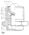
- the ball catch consists of a spherical half-shell 1 deep-drawn from sheet metal, in which the bearing bed 2 is designed in the form of small bearing balls 3.
- the detent ball 4 is mounted in this bed, which is held by a snap ring 6 inserted into an inner groove 5 at the upper edge of the ball half-shell 1. In the inserted state, this snap ring 6 has a smaller inner diameter than the diameter of the large ball 4.
- the spherical half-shell 1 is preferably fixedly connected to the guide part 7 in its center by means of spot welding.
- the guide part 7 is designed in the form of a pot, with cylindrical side walls 8 and a curved bottom 9 whose shape is adapted to the curvature of the spherical half-shell 1, so that these two parts lie flat on one another and thus form a good support and connection.
- the pot-shaped guide part 7 is provided with a recess 10, which serves as a spacer for an inserted compression spring 11, closely above its base 9.
- This ball catch is inserted into a bushing 12 which has a cylindrical cross section on the inside. At one end, the bushing 12 is provided with an inwardly projecting collar 13 against which the edges of the spherical half-shell 1 or the snap ring 6 inserted there abut under the pressure of the spring 11.
- the compression spring 11 inserted into the pot-shaped guide part is supported with its opposite end on a floor in the form of a snap disk 14, which is incorporated in a groove 15 at the end of the bushing 12 opposite the collar 13.
- Rolling elements 16 are guided in a cage 17 between the guide part 7 and the inner surface of the bushing 12, so that the guide part and thus the spherical half-shell can be pressed into the bushing 12 in a slightly movable manner against the pressure of the spring 11.
- a recessed dome 18 is formed in the center of the spherical half-shell and a ball-free space 19 is located on the upper edge of the spherical half-shell 1. Because of this arrangement of dome 18 and free upper edge space 19, the small balls 3 of the bearing bed 2 are freely movable in all directions and flowable so that the detent ball can rotate in any way without any sliding friction in its bearing bed instead of rolling friction or rolling friction due to a jam.
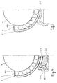
- the largest diameter rRK of the detent ball 4 is indicated by a dashed line and the smallest inner diameter of the snap ring 6 at its lower edge in the inserted state is larger than the largest diameter of the detent ball 4 in accordance with FIG. 3.
- the detent ball can therefore be inserted after the snap ring has been inserted 6 are inserted into the groove 5 after the ball half-shell 1 is filled with the small bearing balls 3.
- the snap ring 6 is pressed into a flat position according to FIG. 4 with deformation, so that its free inside diameter is then smaller than the largest diameter of the detent ball 4 and thus a hold of the detent ball 4 is secured in its bed . This presupposes that the snap ring 6 is deformable and retains this shape and position after being pressed into the flat position according to FIG. 4.
- the snap ring 6 is made either of thin and / or of sufficient soft material.
- the snap ring 6 is designed in such a way that, in the inserted state, its free inside diameter is smaller than the diameter of the locking ball, but only so much smaller that the locking ball still "snaps""can be helpful can be if the inside of the snap ring 6 is slightly chamfered, so that the lower edge has a smaller free diameter than the upper edge of the inner surface. Since the rolling tracks for the rolling elements, namely the balls 16 on the guide part and the small bearing balls 3 in the spherical half-shell, are formed both on the guide part 7 and on the spherical half-shell 1, these parts must be formed after the molding, after the deep-drawing harden.
- This hardening process can be carried out after the two parts have been connected to one another, for example by spot welding. This leads to a not inconsiderable improvement in the economic efficiency in the manufacturing process.
- the snap ring 6 can even be hardened in the inserted state if it is designed in the manner described in the immediately preceding paragraph.
- the upper edge of the cubic half-shell can also be designed according to the invention in such a way that projections which are pressed inward are arranged there and hold the snap ring 6 in its position.
- These projections can be designed in such a way that they allow the snap-in ball 4 to snap in and hold them securely after the snap-in.
- connection between the hemispherical shell 1 and the guide part 7 can, as already mentioned, be made by means of spot welding. It is also possible to generate or to lower the central recessed cap 18 at the same time by means of the spot welding electrode.
- the spherical half-shell and the guide part are firmly connected to one another by means of a centrally arranged rivet 20. With this type of connection as well, it is possible to simultaneously lower the central spherical cap 18 in the spherical half-shell when attaching and inserting the rivet 20.
- the ball half-shell and the guide part are connected to one another by means of a screw 21, the embodiment of the screw 21 shown in FIG.
- This counterpart 22 is designed such that it partially contains the inward curvature of the bottom of the guide part and on its circumference at least in a part directed towards the floor limits the space that the compression spring 11 takes up. As a result, the spring 11 can be guided or additionally held in the area of its last turns.
- connection between the guide part and the spherical half-shell can also be carried out in a different manner, for example in the manner that a central rivet pin projects from the part 21, through the bore in the bottom 9 of the guide part 7 and in the Ball half-shell 1 is passed and then deformed above the ball half-shell to the rivet head.
- the rolling elements or balls 16 which support the guide part 7 in the interior of the bushing 12 are guided in a cage 17 which prevents individual balls or even rows of balls from being displaced relative to one another.
- This arrangement is extremely important because when the locking ball 4 is loaded by a very obliquely sideways force, the guide part can tilt and, as a result, the balls 16 are not held in certain circumferential areas of the guide part due to the required bearing play and move in the direction shift the force of gravity relative to the adjacent held or pinched balls. During the next axial movement, that is to say when the locking ball is pushed in or pushed out under the action of the compression spring 11, these displaced balls 16 then prevent the locking ball from moving.
- the arrangement according to the invention offers a very advantageous development in that the guide part 7 can be resilient.
- one or more axially parallel slots 23 are arranged in the guide part and the guide part is designed such that its outer diameter is larger than the largest inner diameter between the bearing bodies or bearing balls 16.
- the guide part lies after insertion into the Bush resiliently against the bearing body or bearing balls 16 and holds them non-positively. There is then no longer any play between the roller tracks formed on the outside of the guide part and the rolling elements on the one hand and the guide tracks and rolling elements formed on the inside of the bushing on the other hand.
- the rolling elements are, as it were, clamped between the guide part and the bush. It can be seen that under these conditions it is no longer possible to move individual balls or rows of balls with respect to neighboring balls. This special way of carrying out the storage even allows a ball cage to be dispensed with.
- the guide part is designed according to FIG. 6 in such a way that the roller tracks for the balls 16 are arranged as inwardly curved wall parts 24 between the slots 23.
- These wall parts 24 are formed resiliently to the outside and therefore lie closely against the balls, so that the balls 16 are not only guided non-positively and are thus prevented from moving in the axial direction, but due to the inwardly curved design of the wall parts 24 with the roller tracks for the balls are also effectively prevented from rotating the guide member 7.
- 8 shows a section through such an embodiment.
- the guide part 7 is designed, for example, with a square outline, so that its walls 25 and thus the rolling element tracks are flat.
- the rolling elements can be designed as rollers or needles 26, the corresponding rolling element raceways in the bushing 12, of course, also being flat and opposite the wall parts 25 of the guide part 7 (FIG. 9).
Landscapes
- Physics & Mathematics (AREA)
- General Physics & Mathematics (AREA)
- Engineering & Computer Science (AREA)
- Automation & Control Theory (AREA)
- Bearings For Parts Moving Linearly (AREA)
- Pivots And Pivotal Connections (AREA)
- Gear-Shifting Mechanisms (AREA)
- Mechanical Control Devices (AREA)
- Mechanical Operated Clutches (AREA)
- Seats For Vehicles (AREA)
Applications Claiming Priority (2)
| Application Number | Priority Date | Filing Date | Title |
|---|---|---|---|
| DE3814374 | 1988-04-28 | ||
| DE3814374A DE3814374A1 (de) | 1988-04-28 | 1988-04-28 | Kugelraste |
Publications (3)
| Publication Number | Publication Date |
|---|---|
| EP0339441A2 EP0339441A2 (de) | 1989-11-02 |
| EP0339441A3 EP0339441A3 (de) | 1991-01-16 |
| EP0339441B1 true EP0339441B1 (de) | 1994-06-15 |
Family
ID=6353104
Family Applications (1)
| Application Number | Title | Priority Date | Filing Date |
|---|---|---|---|
| EP89106961A Expired - Lifetime EP0339441B1 (de) | 1988-04-28 | 1989-04-19 | Kugelraste |
Country Status (5)
| Country | Link |
|---|---|
| US (1) | US4961650A (enExample) |
| EP (1) | EP0339441B1 (enExample) |
| JP (1) | JP2845936B2 (enExample) |
| DE (2) | DE3814374A1 (enExample) |
| ES (1) | ES2054920T3 (enExample) |
Cited By (5)
| Publication number | Priority date | Publication date | Assignee | Title |
|---|---|---|---|---|
| WO1991017980A1 (en) * | 1990-05-17 | 1991-11-28 | Schering Corporation | Disulfide derivatives of mercaptoacylamino acids |
| WO1992009834A1 (de) * | 1990-12-03 | 1992-06-11 | Ina Wälzlager Schaeffler Kg | Kugelraste für die sicherung von verstellpositionen eines stellelementes, insbesondere eines schaltgestänges für kraftfahrzeuge |
| WO1992014079A1 (de) * | 1991-02-06 | 1992-08-20 | Ina Wälzlager Schaeffler Kg | Arretiervorrichtung |
| DE19950611A1 (de) * | 1999-10-21 | 2001-04-26 | Schaeffler Waelzlager Ohg | Schaltarretierung |
| CN104033584A (zh) * | 2014-04-22 | 2014-09-10 | 宁波高发汽车控制系统股份有限公司 | 一种汽车换档器 |
Families Citing this family (30)
| Publication number | Priority date | Publication date | Assignee | Title |
|---|---|---|---|---|
| DE9105258U1 (de) * | 1991-04-29 | 1991-07-25 | INA Wälzlager Schaeffler KG, 8522 Herzogenaurach | Arretierbolzen |
| DE9111463U1 (de) * | 1991-09-14 | 1992-10-15 | Schwarzbich, Jörg, 4800 Bielefeld | Federraste |
| DE4220817A1 (de) * | 1992-06-25 | 1994-01-05 | Schaeffler Waelzlager Kg | Schaltarretierung |
| DE4220818A1 (de) * | 1992-06-25 | 1994-01-05 | Schaeffler Waelzlager Kg | Schaltarretierung |
| DE4240298A1 (de) * | 1992-12-01 | 1994-06-09 | Schaeffler Waelzlager Kg | Arretierelement |
| DE4312997A1 (de) * | 1993-04-21 | 1994-10-27 | Schaeffler Waelzlager Kg | Schaltarretierung |
| DE9309611U1 (de) * | 1993-06-29 | 1993-08-19 | INA Wälzlager Schaeffler KG, 91074 Herzogenaurach | Schaltarretierung |
| DE9316348U1 (de) * | 1993-10-26 | 1993-12-16 | INA Wälzlager Schaeffler KG, 91074 Herzogenaurach | Arretierung |
| DE9319480U1 (de) * | 1993-12-20 | 1994-03-17 | INA Wälzlager Schaeffler KG, 91074 Herzogenaurach | Arretierelement |
| DE4422662C2 (de) * | 1994-06-28 | 2003-08-28 | Torrington Nadellager Gmbh | Radiallageranordnung |
| DE19509880C1 (de) * | 1995-03-17 | 1996-11-07 | Schwarzbich Joerg | Arretierschraube für Kraftfahrzeuggetriebe |
| US5516211A (en) * | 1995-07-28 | 1996-05-14 | The Rexroth Corporation | Ball transfer unit |
| US6566864B1 (en) * | 2000-09-01 | 2003-05-20 | Ford Global Technologies, L.L.C. | Angular position sensor for vehicle suspension |
| JP2003239952A (ja) * | 2002-02-12 | 2003-08-27 | Takai Corporation:Kk | 確実に回転するボールを持ったツバ付きボールプランジャー |
| DE10311208A1 (de) * | 2003-03-14 | 2004-09-23 | Ina-Schaeffler Kg | Arretiervorrichtung oder Kugelrolle |
| DE20314448U1 (de) * | 2003-09-17 | 2005-01-27 | Metz, Ulrich | Massagegerät |
| US7360756B2 (en) * | 2005-03-31 | 2008-04-22 | Delphi Technologies, Inc. | Vibration isolating bushing with embedded speed/position sensor |
| US20060220638A1 (en) * | 2005-03-31 | 2006-10-05 | Urquidi Carlos A | Angular position sensor |
| US7370853B2 (en) | 2005-03-31 | 2008-05-13 | Delphi Technologies, Inc. | Vibration isolating bushing with embedded angular position sensor |
| FR2960183B1 (fr) * | 2010-05-19 | 2015-05-15 | Airbus Operations Sas | Ensemble de support et de guidage d'un element mobile par rapport a un element fixe |
| JP5033907B2 (ja) * | 2010-10-26 | 2012-09-26 | 株式会社フジクラ | フレキシブルプリント基板の観察方法及び観察装置 |
| CN104030033B (zh) * | 2014-06-11 | 2016-07-13 | 昆山龙腾光电有限公司 | 撑杆装置和具有撑杆装置的基板承载装置 |
| CN106481812B (zh) * | 2015-09-02 | 2018-05-11 | 浙江道成汽车部件股份有限公司 | 汽车旋入式换挡限位器及其换挡限位器推杆的制造方法 |
| AU2017213885B2 (en) * | 2016-02-05 | 2020-06-11 | Sdc Technologies, Inc. | Fog resistant coatings |
| DE102016203702B3 (de) * | 2016-03-08 | 2017-05-18 | Schaeffler Technologies AG & Co. KG | Arretierelement zur Sicherung von Verstellpositionen |
| JP6684154B2 (ja) * | 2016-06-01 | 2020-04-22 | 株式会社ジェイテクト | ボールねじ装置、ボールねじ装置を用いたステアリング装置及びボールねじ装置のリテーナの製造方法 |
| CN106286798A (zh) * | 2016-08-25 | 2017-01-04 | 宁波高发汽车控制系统股份有限公司 | 换挡操作机构总成 |
| CN106286799A (zh) * | 2016-08-25 | 2017-01-04 | 宁波高发汽车控制系统股份有限公司 | 汽车换挡机构总成 |
| DE102016222491A1 (de) | 2016-11-16 | 2018-05-17 | Schaeffler Technologies AG & Co. KG | Arretierelement |
| DE102017111981A1 (de) | 2017-05-31 | 2018-12-06 | Gns Kv Gmbh | Schaltlager und Verfahren zur Herstellung eines Lagerteils für ein Schaltlager |
Family Cites Families (12)
| Publication number | Priority date | Publication date | Assignee | Title |
|---|---|---|---|---|
| AT9377B (de) * | 1900-07-10 | 1902-10-10 | Acme Ball Bearing Caster Compa | Möbelrolle. |
| US2495599A (en) * | 1944-11-22 | 1950-01-24 | Pinnick Alfred | Castor for furniture and the like |
| US3317257A (en) * | 1964-09-02 | 1967-05-02 | Odd N Oddsen | Roller bearing and a method of making same |
| AU441779B2 (en) * | 1967-02-28 | 1973-10-22 | William Jenkins Albert | Improvements in or relating to castors |
| JPS5861950U (ja) * | 1981-10-20 | 1983-04-26 | トヨタ自動車株式会社 | 手動変速機のシフト機構 |
| US4553795A (en) * | 1982-04-02 | 1985-11-19 | Shozo Takagi | Mold supporting arrangement |
| DE3277066D1 (en) * | 1982-04-19 | 1987-10-01 | Caterpillar Inc | A mounting apparatus for a control lever |
| US4696583A (en) * | 1984-05-25 | 1987-09-29 | The Boeing Company | Ball support assembly |
| US4660994A (en) * | 1986-04-23 | 1987-04-28 | Camillo Masciarelli | Anti-friction element |
| US4679682A (en) * | 1986-08-18 | 1987-07-14 | Brunswick Corporation | Marine drive shift mechanism with detent canister centered neutral |
| DE8630656U1 (de) * | 1986-11-15 | 1987-10-01 | Schwarzbich, Jörg, 4800 Bielefeld | Kugelraste |
| DE8713965U1 (de) * | 1987-01-30 | 1987-12-03 | INA Wälzlager Schaeffler KG, 8522 Herzogenaurach | Arretierbolzen, insbesondere für Schaltstangen in Kraftfahrzeuggetrieben |
-
1988
- 1988-04-28 DE DE3814374A patent/DE3814374A1/de active Granted
-
1989
- 1989-04-19 DE DE58907875T patent/DE58907875D1/de not_active Expired - Lifetime
- 1989-04-19 ES ES89106961T patent/ES2054920T3/es not_active Expired - Lifetime
- 1989-04-19 EP EP89106961A patent/EP0339441B1/de not_active Expired - Lifetime
- 1989-04-28 US US07/344,375 patent/US4961650A/en not_active Expired - Lifetime
- 1989-04-28 JP JP1107900A patent/JP2845936B2/ja not_active Expired - Fee Related
Cited By (7)
| Publication number | Priority date | Publication date | Assignee | Title |
|---|---|---|---|---|
| WO1991017980A1 (en) * | 1990-05-17 | 1991-11-28 | Schering Corporation | Disulfide derivatives of mercaptoacylamino acids |
| WO1992009834A1 (de) * | 1990-12-03 | 1992-06-11 | Ina Wälzlager Schaeffler Kg | Kugelraste für die sicherung von verstellpositionen eines stellelementes, insbesondere eines schaltgestänges für kraftfahrzeuge |
| WO1992014079A1 (de) * | 1991-02-06 | 1992-08-20 | Ina Wälzlager Schaeffler Kg | Arretiervorrichtung |
| DE19950611A1 (de) * | 1999-10-21 | 2001-04-26 | Schaeffler Waelzlager Ohg | Schaltarretierung |
| FR2800145A1 (fr) | 1999-10-21 | 2001-04-27 | Schaeffler Waelzlager Ohg | Doigt de positionnement pour arbre et barre de commande de vitesses et coulisses |
| CN104033584A (zh) * | 2014-04-22 | 2014-09-10 | 宁波高发汽车控制系统股份有限公司 | 一种汽车换档器 |
| CN104033584B (zh) * | 2014-04-22 | 2016-05-25 | 宁波高发汽车控制系统股份有限公司 | 一种汽车换档器 |
Also Published As
| Publication number | Publication date |
|---|---|
| JP2845936B2 (ja) | 1999-01-13 |
| JPH0243607A (ja) | 1990-02-14 |
| DE58907875D1 (de) | 1994-07-21 |
| ES2054920T3 (es) | 1994-08-16 |
| EP0339441A2 (de) | 1989-11-02 |
| DE3814374C2 (enExample) | 1991-01-24 |
| DE3814374A1 (de) | 1989-11-09 |
| US4961650A (en) | 1990-10-09 |
| EP0339441A3 (de) | 1991-01-16 |
Similar Documents
| Publication | Publication Date | Title |
|---|---|---|
| EP0339441B1 (de) | Kugelraste | |
| DE68904117T2 (de) | Kugelgelenk. | |
| DE69812324T2 (de) | Von Aussen einsteckbare Kugelrücklaufsysteme für Kugelumlaufspindeln und Verfahren zu deren Montage | |
| DE2326018B2 (de) | Kugelgelenk | |
| EP1194702A1 (de) | Kugelhülsengelenk | |
| DE4324472A1 (de) | Einschnappbare Kugel- und Endanschlußteil-Anordnung | |
| DE69114224T2 (de) | Kombiniertes Axial-Radiallager. | |
| DD250740A5 (de) | Rollelement | |
| EP0559652B1 (de) | Kugelraste für die sicherung von verstellpositionen eines stellelementes, insbesondere eines schaltgestänges für kraftfahrzeuge | |
| DE3639120C2 (enExample) | ||
| DE19833982A1 (de) | Pendelgleitlager | |
| DE69703347T2 (de) | Übertragungsgelenkkreuz und entsprechendes übertragungsgelenk | |
| DE29922702U1 (de) | Fahrzeugsitz mit Welle und Lagerstelle | |
| DE19646310A1 (de) | Radial-Wälzlager | |
| DE3641117A1 (de) | Scharnier | |
| DE4005285A1 (de) | Tuerfeststeller fuer kraftwagentueren | |
| DE102017108370B4 (de) | Wälzgewindetrieb | |
| WO2018166547A1 (de) | Spindelmutter für einen kugelgewindetrieb und verfahren zur herstellung einer spindelmutter | |
| DE10338873B4 (de) | Ventilkipphebel | |
| DE2710768A1 (de) | Kugel-pfannen-gelenk | |
| EP1282784B1 (de) | Synchronkörper einer synchronisiereinrichtung | |
| DE3301712C2 (enExample) | ||
| DE102007053149A1 (de) | Kombiniertes Axial-Radial-Wälzlager | |
| WO2020007394A1 (de) | Lageranordnung sowie darin vorgesehenes halteringelement | |
| DE10320948B4 (de) | Kugelgewindetrieb |
Legal Events
| Date | Code | Title | Description |
|---|---|---|---|
| PUAI | Public reference made under article 153(3) epc to a published international application that has entered the european phase |
Free format text: ORIGINAL CODE: 0009012 |
|
| AK | Designated contracting states |
Kind code of ref document: A2 Designated state(s): DE ES FR GB IT SE |
|
| PUAL | Search report despatched |
Free format text: ORIGINAL CODE: 0009013 |
|
| AK | Designated contracting states |
Kind code of ref document: A3 Designated state(s): DE ES FR GB IT SE |
|
| 17P | Request for examination filed |
Effective date: 19910306 |
|
| 17Q | First examination report despatched |
Effective date: 19920708 |
|
| GRAA | (expected) grant |
Free format text: ORIGINAL CODE: 0009210 |
|
| AK | Designated contracting states |
Kind code of ref document: B1 Designated state(s): DE ES FR GB IT SE |
|
| REF | Corresponds to: |
Ref document number: 58907875 Country of ref document: DE Date of ref document: 19940721 |
|
| REG | Reference to a national code |
Ref country code: ES Ref legal event code: FG2A Ref document number: 2054920 Country of ref document: ES Kind code of ref document: T3 |
|
| GBT | Gb: translation of ep patent filed (gb section 77(6)(a)/1977) |
Effective date: 19940715 |
|
| ITF | It: translation for a ep patent filed | ||
| ET | Fr: translation filed | ||
| EAL | Se: european patent in force in sweden |
Ref document number: 89106961.9 |
|
| PLBE | No opposition filed within time limit |
Free format text: ORIGINAL CODE: 0009261 |
|
| STAA | Information on the status of an ep patent application or granted ep patent |
Free format text: STATUS: NO OPPOSITION FILED WITHIN TIME LIMIT |
|
| 26N | No opposition filed | ||
| REG | Reference to a national code |
Ref country code: GB Ref legal event code: IF02 |
|
| PGFP | Annual fee paid to national office [announced via postgrant information from national office to epo] |
Ref country code: GB Payment date: 20080314 Year of fee payment: 20 |
|
| PGFP | Annual fee paid to national office [announced via postgrant information from national office to epo] |
Ref country code: ES Payment date: 20080403 Year of fee payment: 20 Ref country code: DE Payment date: 20080424 Year of fee payment: 20 |
|
| PGFP | Annual fee paid to national office [announced via postgrant information from national office to epo] |
Ref country code: IT Payment date: 20080429 Year of fee payment: 20 |
|
| PGFP | Annual fee paid to national office [announced via postgrant information from national office to epo] |
Ref country code: SE Payment date: 20080428 Year of fee payment: 20 |
|
| PGFP | Annual fee paid to national office [announced via postgrant information from national office to epo] |
Ref country code: FR Payment date: 20080331 Year of fee payment: 20 |
|
| REG | Reference to a national code |
Ref country code: GB Ref legal event code: PE20 Expiry date: 20090418 |
|
| EUG | Se: european patent has lapsed | ||
| REG | Reference to a national code |
Ref country code: ES Ref legal event code: FD2A Effective date: 20090420 |
|
| PG25 | Lapsed in a contracting state [announced via postgrant information from national office to epo] |
Ref country code: ES Free format text: LAPSE BECAUSE OF EXPIRATION OF PROTECTION Effective date: 20090420 |
|
| PG25 | Lapsed in a contracting state [announced via postgrant information from national office to epo] |
Ref country code: GB Free format text: LAPSE BECAUSE OF EXPIRATION OF PROTECTION Effective date: 20090418 |