EP0337914B1 - A continuous paper and the like delivery mechanism - Google Patents
A continuous paper and the like delivery mechanism Download PDFInfo
- Publication number
- EP0337914B1 EP0337914B1 EP89500040A EP89500040A EP0337914B1 EP 0337914 B1 EP0337914 B1 EP 0337914B1 EP 89500040 A EP89500040 A EP 89500040A EP 89500040 A EP89500040 A EP 89500040A EP 0337914 B1 EP0337914 B1 EP 0337914B1
- Authority
- EP
- European Patent Office
- Prior art keywords
- paper
- shaft
- rollers
- band
- roller
- Prior art date
- Legal status (The legal status is an assumption and is not a legal conclusion. Google has not performed a legal analysis and makes no representation as to the accuracy of the status listed.)
- Expired - Lifetime
Links
Images


Classifications
-
- A—HUMAN NECESSITIES
- A47—FURNITURE; DOMESTIC ARTICLES OR APPLIANCES; COFFEE MILLS; SPICE MILLS; SUCTION CLEANERS IN GENERAL
- A47K—SANITARY EQUIPMENT; ACCESSORIES THEREFOR, e.g. TOILET ACCESSORIES
- A47K10/00—Body-drying implements; Toilet paper; Holders therefor
- A47K10/24—Towel dispensers; Toilet paper dispensers
- A47K10/32—Dispensers for paper towels or toilet paper
- A47K10/34—Dispensers for paper towels or toilet paper dispensing from a web, e.g. with mechanical dispensing means
- A47K10/36—Dispensers for paper towels or toilet paper dispensing from a web, e.g. with mechanical dispensing means with mechanical dispensing, roll switching or cutting devices
- A47K10/3631—The cutting devices being driven manually
- A47K10/3643—The cutting devices being driven manually by pulling the paper
Definitions
- the present invention relates to mechanisms for delivering pieces of paper or the like material, which are severed from a continuous source of continuous paper band, such as those used, for example, for supplying paper towels for hand drying or cleaning purposes.
- Mechanisms for delivering pieces of continuous or band paper comprising a pair of mutually tangent pressure rollers are well known, wherein a first one of the said rollers is mounted rotating about a fixed axis while the other, second roller, is mounted on an oscillating frame which is spring biased against the first roller, the end of a paper band issuing from a bobbin being caught between both rollers, the mechanism further comprising a locking device associated to the shaft of one of the rollers and restricting the length of paper which is delivered each time that a pull is applied to the paper band end, a timer holding the mechanism locked during a restricted period, and an ejector device operating one of the rollers once a paper band length has been withdrawn, to eject a short paper length to make its grasping easier, the ejector device including a cam biased by a spring, the ensemble being located within a box provided with a paper outlet opening.
- a mechanism of the above features makes the subject of the Spanish Utility Model No 290 203 of which the applicant is the owner.
- the patent DE-A-2 527 218 discloses a mechanism comprising the features indicated in the preamble of the accompanying Claim 1, for delivering a continuous band of paper or the like which allows for supplying pieces of different lengths.
- the continuous paper band is drawn from a bobbin and guided between transport rollers and pressure rollers, the transport rollers being coupled to a timing and locking device.
- the transport rollers are mounted on a hollow axle which in turn is mounted on a concentric shaft coupled to the timing and locking device.
- This mechanism is also provided with a gear between the hollow axle and the shaft, the sprocket wheels forming the gear being optionally engageable in order to obtain different gear ratio. Said different gear ratio provides the pieces of different lengths.
- This patent also describes several gear embodiments so as to obtain different gear ratio.
- the sprocket wheels are mounted on the hollow axle and on the shaft, and a third axle with at least two different sprocket wheels is always necessary.
- the ejector device which automatically supplies a short paper length once a user has taken out the band and detached a length of it corresponding to a towel or the like dose, acts directly upon the shaft of one of the band drawing rollers by means of a cam biased by a spring which is released under the control of a timing system and which is loaded through a reducing transmission connected to the shaft of the said roller.
- a cam biased by a spring which is released under the control of a timing system and which is loaded through a reducing transmission connected to the shaft of the said roller.
- the triggering of the mechanism supplying the short paper length operates in two steps with a short time period between these latter, which may induce the user to apply a pull on the paper band in order to obtain a new dose, in the wrong timing thus causing the mechanism to become blocked.
- the device for cutting the pulled paper band can also be subject of improvement with a view of simplifying its conformation though with no loss in efficiency.
- the spring loading cam of the ejector device for delivering the short paper length when the mechanism has been unlocked is mounted on the shaft of a set of sprocket wheels having different diameters and adapted to be selectively engaged by another set of different diameter sprocket wheels secured to the shaft of one of the paper band drawing rollers, both sets of wheels forming a changeable gear.
- the ejector device and the timer winding device which are of a common construction, are mounted on the same shaft of the set of sprockets selectively meshing with the sprockets mounted in a position which is displaceable at will on the shaft of one of the paper band drawing rollers.
- the oscillating frame carrying mounted thereon the movable roller is formed with an arcuate gutter or ramp located immediately under the opening through which the paper band coming from the supply bobbin issues, the said gutter or ramp receiving the engagement of one end of springs having their opposite ends anchored in fixed points of the support structure of the mechanism, thus forcing the supported roller to rest onto the other roller.
- the border of the paper exit opening formed in the enclosure containing the mechanism has a cutting edge, which can be toothed, for cutting the withdrawn paper band.
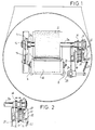
- the continuous paper delivery mechanism consists, in the drawings, of two rollers 1,2 trapping a paper band 3 coming from a bobbin 4 located within a container 5, the bottom of which is shaped as a funnel 6, according to a known embodiment.
- the roller 1 is mounted on an oscillating frame 7 provided with wings 8 which are articulated about a shaft 9 mounted on fixed lugs 10.
- This oscillating support 8 is biased by springs 11 having one end anchored to the fixed lugs 10 and the opposite end resting upon the back of an arcuate gutter or ramp 12 extending upwards of the support, thus forming a guide for the paper band 3 at the outlet of this latter from the funnel 6 (Fig. 3).
- a conventional escapement device formed of a sprocket wheel 13 against which a tooth 14 impinges under the biasing of a spring 15 to prevent the back motion of the roller 2, is mounted at one end of the shaft 2a of the said roller 2.
- the opposite end of the shaft 2a has mounted thereon two sprocket wheels 16,17 having different diameters and adapted to mesh selectively and alternatively with two sprocket wheels 18,19 which are fast with a shaft 20 mounted for rotation on a support 21.
- the same shaft 20 has secured thereon a cam 22 with a spring 23 constituting the automatic ejector device of the shaft 2a for delivery of a short run or length of the band 3.
- This ejector device is associated, according to a known embodiment, to a timer device formed of two mutually faced suction cups 24,25 of which the cup 24 can be displaced by a movable arm 26 in turn operated by a cam 27 joined to the shaft 20 of the sprocket wheels 18,19.
- the described mechanism is housed in a pan 28 having an opening 29 for the outlet of the band 3a and formed with a toothed wing 30 for severing the delivered band.
- toothed cutting edge 30 instead of a cutter blade joined by conventional means to the structure which the mechanism is secured upon, for severing the delivered band run 3a.
- This cutting edge 30 may be obtained directly integral with the pan 28, or by inserting on this latter a stiffer part, either of plastics or metallic material.
Landscapes
- Health & Medical Sciences (AREA)
- Public Health (AREA)
- Replacement Of Web Rolls (AREA)
- Paper (AREA)
- Advancing Webs (AREA)
- Telephone Function (AREA)
- Making Paper Articles (AREA)
Priority Applications (1)
| Application Number | Priority Date | Filing Date | Title |
|---|---|---|---|
| AT89500040T ATE86457T1 (de) | 1988-04-11 | 1989-03-30 | Zufuehrmaschine fuer endlosbahn aus papier und dergleichen. |
Applications Claiming Priority (2)
| Application Number | Priority Date | Filing Date | Title |
|---|---|---|---|
| ES8801092A ES2007187A6 (es) | 1988-04-11 | 1988-04-11 | Perfeccionamientos en los mecanismos suministradores de papel continuo y similares. |
| ES8801092 | 1988-04-11 |
Publications (2)
| Publication Number | Publication Date |
|---|---|
| EP0337914A1 EP0337914A1 (en) | 1989-10-18 |
| EP0337914B1 true EP0337914B1 (en) | 1993-03-10 |
Family
ID=8255761
Family Applications (1)
| Application Number | Title | Priority Date | Filing Date |
|---|---|---|---|
| EP89500040A Expired - Lifetime EP0337914B1 (en) | 1988-04-11 | 1989-03-30 | A continuous paper and the like delivery mechanism |
Country Status (5)
| Country | Link |
|---|---|
| EP (1) | EP0337914B1 (es) |
| AT (1) | ATE86457T1 (es) |
| DE (1) | DE68905218T2 (es) |
| ES (1) | ES2007187A6 (es) |
| PT (1) | PT90238B (es) |
Families Citing this family (1)
| Publication number | Priority date | Publication date | Assignee | Title |
|---|---|---|---|---|
| CN108523748B (zh) * | 2018-04-16 | 2024-02-27 | 朱志超 | 一种纸盒 |
Family Cites Families (3)
| Publication number | Priority date | Publication date | Assignee | Title |
|---|---|---|---|---|
| US3575328A (en) * | 1969-01-24 | 1971-04-20 | Georgia Pacific Corp | Dispenser for flexible sheet material and a perforating mechanism adapted to be used therein |
| DE2527218C3 (de) * | 1975-06-19 | 1978-05-18 | Pwa Papierwerke Waldhof-Aschaffenburg Ag, 8000 Muenchen | Handtuchspender |
| CH635996A5 (en) * | 1979-11-22 | 1983-05-13 | Aa 2 S N C | Automatic dispensing apparatus for material in roll form, particularly tissue paper for drying the hands |
-
1988
- 1988-04-11 ES ES8801092A patent/ES2007187A6/es not_active Expired
-
1989
- 1989-03-30 DE DE8989500040T patent/DE68905218T2/de not_active Expired - Fee Related
- 1989-03-30 AT AT89500040T patent/ATE86457T1/de not_active IP Right Cessation
- 1989-03-30 EP EP89500040A patent/EP0337914B1/en not_active Expired - Lifetime
- 1989-04-10 PT PT90238A patent/PT90238B/pt not_active IP Right Cessation
Also Published As
| Publication number | Publication date |
|---|---|
| PT90238A (pt) | 1989-11-10 |
| DE68905218T2 (de) | 1993-09-23 |
| DE68905218D1 (de) | 1993-04-15 |
| EP0337914A1 (en) | 1989-10-18 |
| ATE86457T1 (de) | 1993-03-15 |
| ES2007187A6 (es) | 1989-06-01 |
| PT90238B (pt) | 1994-03-31 |
Similar Documents
| Publication | Publication Date | Title |
|---|---|---|
| DE69520046T2 (de) | Spender sowie schneidvorrichtung für eine aufgewickelte bahn | |
| US5048386A (en) | Feed mechanism for flexible sheet material dispensers | |
| US4552315A (en) | Rolled web dispenser | |
| DE68911392T2 (de) | Rundballenpresse. | |
| DE2835257A1 (de) | Anlage zum aufbringen und wechseln eines schlauchfoermigen schutzueberzuges aus kunststoffolie auf einem klosettsitz und verfahren zum herstellen eines schlauches | |
| KR19990087838A (ko) | 테일실러를 내장한 권취기 | |
| DE2803077C2 (es) | ||
| EP0243906B1 (de) | Verfahren und Vorrichtung zum Herstellen von tragbaren, rohrförmigen Paketen aus Druckprodukten, wie Zeitungen, Zeitschriften und dergleichen | |
| EP1646307B1 (en) | Dispensing device for paper sheets obtained by manual cutting from a continuous band with triggering mechanism for a spare roll | |
| EP0283554B1 (de) | Stoffhandtuchspender und Verfahren zum Betrieb desselben | |
| EP0337914B1 (en) | A continuous paper and the like delivery mechanism | |
| US3893738A (en) | Retractable towel cabinet | |
| DE1554607B2 (de) | Vorrichtung zur Ausgabe einer kontinierlichen Handtuchbahn | |
| CA1115668A (en) | Multiple wound roll dispenser and cutter mechanism for use therein | |
| DE2807056A1 (de) | Geraet zum bedrucken oder anbringen von selbsthaftenden etiketten | |
| DE2451648A1 (de) | Einrichtung zur aufnahme des postwertzeichenstreifens einer frankiermaschine | |
| DE2857074C3 (de) | Vorrichtung zum Zuführen von Einzelblättern von einem in einem Magazin gespeicherten Papierstapel zur Schreibwalze einer Büromaschine | |
| DE2922581A1 (de) | Vorrichtung zur ausgabe von papierabschnitten vorgegebener laenge | |
| DE2205186C3 (de) | Ausgabevorrichtung für Toilettenpapier od. dgl | |
| DE3835023C2 (es) | ||
| DE2427939C3 (de) | Vorrichtung zur Herstellung von Tampons mit Einfuhrvorrichtung | |
| US5672237A (en) | Postage stamp applicator | |
| WO1990001286A1 (en) | Dispenser for rolled webs | |
| DE69606540T2 (de) | Handtuchspender | |
| DE1560427A1 (de) | Selbsttaetige Koetzerzufuehrungsvorrichtung |
Legal Events
| Date | Code | Title | Description |
|---|---|---|---|
| PUAI | Public reference made under article 153(3) epc to a published international application that has entered the european phase |
Free format text: ORIGINAL CODE: 0009012 |
|
| AK | Designated contracting states |
Kind code of ref document: A1 Designated state(s): AT BE CH DE FR GB GR IT LI NL SE |
|
| 17P | Request for examination filed |
Effective date: 19900320 |
|
| 17Q | First examination report despatched |
Effective date: 19911121 |
|
| GRAA | (expected) grant |
Free format text: ORIGINAL CODE: 0009210 |
|
| AK | Designated contracting states |
Kind code of ref document: B1 Designated state(s): AT BE CH DE FR GB GR IT LI NL SE |
|
| PG25 | Lapsed in a contracting state [announced via postgrant information from national office to epo] |
Ref country code: GR Free format text: LAPSE BECAUSE OF FAILURE TO SUBMIT A TRANSLATION OF THE DESCRIPTION OR TO PAY THE FEE WITHIN THE PRESCRIBED TIME-LIMIT Effective date: 19930310 Ref country code: BE Effective date: 19930310 |
|
| REF | Corresponds to: |
Ref document number: 86457 Country of ref document: AT Date of ref document: 19930315 Kind code of ref document: T |
|
| REF | Corresponds to: |
Ref document number: 68905218 Country of ref document: DE Date of ref document: 19930415 |
|
| ITF | It: translation for a ep patent filed | ||
| ET | Fr: translation filed | ||
| PLBE | No opposition filed within time limit |
Free format text: ORIGINAL CODE: 0009261 |
|
| STAA | Information on the status of an ep patent application or granted ep patent |
Free format text: STATUS: NO OPPOSITION FILED WITHIN TIME LIMIT |
|
| 26N | No opposition filed | ||
| EAL | Se: european patent in force in sweden |
Ref document number: 89500040.4 |
|
| PGFP | Annual fee paid to national office [announced via postgrant information from national office to epo] |
Ref country code: SE Payment date: 19950307 Year of fee payment: 7 Ref country code: AT Payment date: 19950307 Year of fee payment: 7 |
|
| PGFP | Annual fee paid to national office [announced via postgrant information from national office to epo] |
Ref country code: GB Payment date: 19950320 Year of fee payment: 7 Ref country code: FR Payment date: 19950320 Year of fee payment: 7 |
|
| PGFP | Annual fee paid to national office [announced via postgrant information from national office to epo] |
Ref country code: CH Payment date: 19950328 Year of fee payment: 7 |
|
| PGFP | Annual fee paid to national office [announced via postgrant information from national office to epo] |
Ref country code: NL Payment date: 19950331 Year of fee payment: 7 |
|
| PGFP | Annual fee paid to national office [announced via postgrant information from national office to epo] |
Ref country code: DE Payment date: 19950411 Year of fee payment: 7 |
|
| PG25 | Lapsed in a contracting state [announced via postgrant information from national office to epo] |
Ref country code: GB Effective date: 19960330 Ref country code: AT Effective date: 19960330 |
|
| PG25 | Lapsed in a contracting state [announced via postgrant information from national office to epo] |
Ref country code: SE Effective date: 19960331 Ref country code: LI Effective date: 19960331 Ref country code: CH Effective date: 19960331 |
|
| PG25 | Lapsed in a contracting state [announced via postgrant information from national office to epo] |
Ref country code: NL Effective date: 19961001 |
|
| REG | Reference to a national code |
Ref country code: CH Ref legal event code: PL |
|
| GBPC | Gb: european patent ceased through non-payment of renewal fee |
Effective date: 19960330 |
|
| PG25 | Lapsed in a contracting state [announced via postgrant information from national office to epo] |
Ref country code: FR Effective date: 19961129 |
|
| NLV4 | Nl: lapsed or anulled due to non-payment of the annual fee |
Effective date: 19961001 |
|
| PG25 | Lapsed in a contracting state [announced via postgrant information from national office to epo] |
Ref country code: DE Effective date: 19961203 |
|
| EUG | Se: european patent has lapsed |
Ref document number: 89500040.4 |
|
| REG | Reference to a national code |
Ref country code: FR Ref legal event code: ST |
|
| PG25 | Lapsed in a contracting state [announced via postgrant information from national office to epo] |
Ref country code: IT Free format text: LAPSE BECAUSE OF NON-PAYMENT OF DUE FEES;WARNING: LAPSES OF ITALIAN PATENTS WITH EFFECTIVE DATE BEFORE 2007 MAY HAVE OCCURRED AT ANY TIME BEFORE 2007. THE CORRECT EFFECTIVE DATE MAY BE DIFFERENT FROM THE ONE RECORDED. Effective date: 20050330 |