EP0337122A2 - Programmgenerierungssystem für ein Werkstück - Google Patents
Programmgenerierungssystem für ein Werkstück Download PDFInfo
- Publication number
- EP0337122A2 EP0337122A2 EP89104258A EP89104258A EP0337122A2 EP 0337122 A2 EP0337122 A2 EP 0337122A2 EP 89104258 A EP89104258 A EP 89104258A EP 89104258 A EP89104258 A EP 89104258A EP 0337122 A2 EP0337122 A2 EP 0337122A2
- Authority
- EP
- European Patent Office
- Prior art keywords
- machining
- shape
- recited
- list
- tree
- Prior art date
- Legal status (The legal status is an assumption and is not a legal conclusion. Google has not performed a legal analysis and makes no representation as to the accuracy of the status listed.)
- Withdrawn
Links
Images


Classifications
-
- G—PHYSICS
- G05—CONTROLLING; REGULATING
- G05B—CONTROL OR REGULATING SYSTEMS IN GENERAL; FUNCTIONAL ELEMENTS OF SUCH SYSTEMS; MONITORING OR TESTING ARRANGEMENTS FOR SUCH SYSTEMS OR ELEMENTS
- G05B19/00—Programme-control systems
- G05B19/02—Programme-control systems electric
- G05B19/18—Numerical control [NC], i.e. automatically operating machines, in particular machine tools, e.g. in a manufacturing environment, so as to execute positioning, movement or co-ordinated operations by means of programme data in numerical form
- G05B19/402—Numerical control [NC], i.e. automatically operating machines, in particular machine tools, e.g. in a manufacturing environment, so as to execute positioning, movement or co-ordinated operations by means of programme data in numerical form characterised by control arrangements for positioning, e.g. centring a tool relative to a hole in the workpiece, additional detection means to correct position
-
- G—PHYSICS
- G05—CONTROLLING; REGULATING
- G05B—CONTROL OR REGULATING SYSTEMS IN GENERAL; FUNCTIONAL ELEMENTS OF SUCH SYSTEMS; MONITORING OR TESTING ARRANGEMENTS FOR SUCH SYSTEMS OR ELEMENTS
- G05B19/00—Programme-control systems
- G05B19/02—Programme-control systems electric
- G05B19/18—Numerical control [NC], i.e. automatically operating machines, in particular machine tools, e.g. in a manufacturing environment, so as to execute positioning, movement or co-ordinated operations by means of programme data in numerical form
- G05B19/4097—Numerical control [NC], i.e. automatically operating machines, in particular machine tools, e.g. in a manufacturing environment, so as to execute positioning, movement or co-ordinated operations by means of programme data in numerical form characterised by using design data to control NC machines, e.g. CAD/CAM
-
- Y—GENERAL TAGGING OF NEW TECHNOLOGICAL DEVELOPMENTS; GENERAL TAGGING OF CROSS-SECTIONAL TECHNOLOGIES SPANNING OVER SEVERAL SECTIONS OF THE IPC; TECHNICAL SUBJECTS COVERED BY FORMER USPC CROSS-REFERENCE ART COLLECTIONS [XRACs] AND DIGESTS
- Y02—TECHNOLOGIES OR APPLICATIONS FOR MITIGATION OR ADAPTATION AGAINST CLIMATE CHANGE
- Y02P—CLIMATE CHANGE MITIGATION TECHNOLOGIES IN THE PRODUCTION OR PROCESSING OF GOODS
- Y02P90/00—Enabling technologies with a potential contribution to greenhouse gas [GHG] emissions mitigation
- Y02P90/02—Total factory control, e.g. smart factories, flexible manufacturing systems [FMS] or integrated manufacturing systems [IMS]
Definitions
- the present invention is directed to a system which generates a part program for a numerical control machine tool from a part definition drawing and more particularly to a system which plans the order of machining operations and produces the numerical control program code for the sequence of manufacturing operations which includes selecting the proper tools, feed speeds and machine tool.
- a part-designer will sit down at a CAD/CAM design work station and produce a drawing for the desired part.
- the drawing includes notations as to type of rough stock material and dimensions of the part.
- the drawing is given to a numerical control part programmer, a person who specializes in creating a numerical control part program from the drawing.
- the part programmer uses machine specifications to pick the particular machine to be used based on rough stock size, the physical characteristics of the machine, possible machining speeds as compared to the appropriate speeds for the material using the tools necessary for the different machining operations, the number of tools the machine will hold and whether the part must be manually turned around.
- the part program is then provided to a computer program called a code processor that generates the actual numerical control machine code for controlling the target machine.
- the program is then test executed by a machine tool and if bugs are discovered, the part-programmer revises the program.
- a macro-program is a program that is designed for a specific type machining operation and in which the various machining parameters, such as feeds and speeds, number of passes, length of each pass, etc. are left as variables to be set by a macrocall statement.
- a macro-program is very similar in function to a subroutine in other types of computer languages. Even when an extensive part program library including part macro-programs is available, the time between the initial part request and the finished product is very long. As can be seen from the above discussion, there is a need in the machine tool industry for a system which will generate part programs directly from drawings to speed up the process of producing the desired part and reduce the lead time necessary for manufacturing the part.
- the present offers a part-program reducing the lead time between the request for a particular part and the machining of that part, at the same time reducing manpower costs.
- the above objects can be accomplished by a system that takes a drawing definition produced by a CAD/CAM system and produces a "ready to execute" part-program.
- the system uses the drawing definition to produce a sequence of operations which will produce the part.
- the operations are then used to select particular processes (macro-programs) based on the shape to be machined during each operation step.
- the process selection also specifies the rough machining speeds and tools necessary for rough machining the part.
- a finishing or contouring process is produced.
- An appropriate machine is selected based on part material, number of tools and rough stock size.
- the resulting part program is transferred to a code processor which produces the machine control code for the particular machining tool selected.
- the invention in its broad form resides in method and apparatus for automatically generating a numerical control program from a part-drawing, of a workpiece or part to be made by machining said numerical control program being of the type suitable for machining and producing a required workpiece or part, said apparatus comprising: means for reading a geometry of the part from the part-drawing by automatically recognizing and noting points, curves, surfaces and conics as required on a finished part; characterized by shape means for generating a shape signature which is representative of the read geometry; and programming means for generating the numerical control program from the shape signature.
- a bottom rough stock boundary in a turning operation is the axis of rotation or symmetry for the part and a top rough stock boundary is set at the radius of the rough stock.
- a conventional CAD/CAM system 10 is used by the part designer to produce a drawing.
- the CAD/CAM system provides a shape signature to the present invention which includes a definition for each surface on the part.
- the shape signature also includes the type of material from which the part is to be made and the rough stock size (left, right, top and bottom boundaries from a reference) and finish surface tolerance.
- An appropriate CAD/CAM system is a Sun Microsystems work station available from Cimlinc, Inc. of Elk Grove Village, Illinois. This system preferably uses the CIMLINC/CIMCAD module also available from Cimlinc, Inc. which will produce an appropriate shape signature.
- the shape signature and other data structures in the present invention are frame oriented, that is, each item of information has a specific location within a frame where each different frame carries predefined information.
- Vertical line, horizontal line and circle line definition frames provide similar information which allows the surfaces of the part to be defined.
- the information which is necessary to define a surface in the APT (Automatic Programmed Tools) machine tool language can be found in the geometric statement section of an APT programming manual.
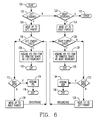
- the shape signature is provided to a computer 12 which includes a process planner module 14 and a code generator module 16.
- a preferred computer is an IBM AT with at least six megabytes of main memory and a hard disc drive with at least 20 megabytes of storage capacity.
- the process planner 14 and code generator 16 are preferably implemented using an expert system shell such as the KEE shell available from Intellicorp of Mountain View, California, U.S.A.
- the process planner 14 examines the shape signature and determines a sequence of operations which will produce the shape defined by the signature.
- the planner 14 also produces a contour machining process as the last operation and, when lathe turning is the type of machining, a facing process as a first operation.
- the particular machine used by the sequence of operations is selected based on the processes selected, the tools used in the processes, the material type and rough stock size.
- the code generator 16 compares the processes to available macro-programs and selects an appropriate macro-program for each process and fills in macro-call frames with the values of the process variables determined by the planner 14.
- the code generator 16 then outputs the completed macro-calls to a code processor 18.
- a conventional code processor 18, such as a Sperry-Univac 1100 executes a conventional machine code process that produces machine code for a target machine tool 20 from the macro-calls.
- An appropriate process is the Computer Integrated Manufacturing/Automatically Programmed Tools - CIM/APT Level 1R1 UP-4078 Revision .3 available from Sperry-Univac.
- the shape signature is preferably an ordered list of surfaces that follow the contour of the part from right to left. If the shape signature is not ordered in this manner it must be sorted into an ordered list.
- Each surface in the shape signature is preferably defined using a grammar in which HS is the symbol that represents a horizontal surface, VS represents a vertical surface, SL designates a slant line, DN indicates a downward direction, UP indicates an upward direction, RD indicates a rounded surface, Q1-Q4 indicate the quadrant in which the curve of the round shape is found and a number indicates the sequence of each type of surface when scanning left to right. Each surface is referenced from the intersection of left and bottom rough stock boundaries.
- Figure 2 illustrates four vertical and three horizontal surfaces defined using the preferred grammar.
- the CAD/CAM system would provide the process planner 14 with a sequence of frames with each frame defining a surface and including a surface symbol which can be extracted to form the following signature list: VS-UP-1, HS-1, VS-UP-2, HS-2, VS-DN-1, HS-3, VS-DN-2.
- the process planner 14 scans the shape signature list from left to right and designates primitive shapes S-1...S-6 (See Figure 3) where a primitive shape has two surfaces adjacent each to other and adjacent primitive shapes share a surface.
- the transition points tp-1...tp-6 for the primitive shapes are also identified where a transition point is the intersection point of two adjacent surfaces in a primitive shape.
- each primitive shape has first and second surfaces and the first surface of each primitive shape is the second surface of the previous primitive shape, except for the first and last primitive shapes.
- S2(0) is set equal to the first surface on the list.
- the primitive shapes are thereby associated with symbolic representations of the surfaces as illustrated in Figure 3 and each primitive shape is provided with a pair of surfaces producing a primitive shape list such as List 1 below:
- each surface has coordinates associated with the starting and ending points and the primitive shape and the transition points are the intersections between surfaces.
- the primitive shape list is then scanned to determine the beginning transition point for a process tree.
- the transition point with the largest Y coordinate encountered in the scanning direction is the beginning point for outer diameter turning work and the lowest transition point is the beginning point for inner diameter turning work.
- the highest transition point would be tp-3.
- the highest transition point in the list is identified by scanning the transition points from left to right and determining the transition point with the largest Y coordinate which also has the smallest X coordinate.
- the transition point list is then divided into sublists at this identified highest transition point as follows in List 4:
- Each node of the process tree except rough stock left boundary (RSL) and rough stock right boundary (RSR), defines a machining operation region and once the process tree is defined for each node in the process tree, it is necessary to determine the top boundary, bottom boundary, left boundary and right boundary for the region designated by each node.
- the top boundary for node tp-7 is the rough stock diameter measured as a radius from the horizontal axis H1
- bottom boundary is the horizontal line HS-4
- the left boundary is the rough stock left boundary (RSL)
- the right boundary is the rough stock right (RSR) boundary.
- transition point tp-9 the top boundary is the bottom boundary of transition point tp-8
- the bottom boundary is the horizontal line HS-5
- the left boundary is the vertical surface VS-5
- the right boundary is the rough stock right (RSR) boundary.
- the top boundary is the bottom boundary of the parent node or the rough stock diameter if the parent is the root process.
- the bottom boundary is found by examining the surfaces of the node and if a horizontal surface is found it is designated as the bottom boundary. If a horizontal surface is not found, then the bottom boundary is set as a horizontal surface (construction line) through the transition point.
- the process planner 14 examines the two surfaces in the primitive shape associated with a node. If the left or first surface is a vertical, slant line or rounded surface it is set as the left boundary, if not one of those surfaces, the left boundary is undefined. If the right or second surface is a vertical, slant line or rounded surface it is set as the right boundary, if not, the right boundary is undefined.
- the rough stock left boundary is assumed 114 as the left boundary for the node in question. If the left boundary does not exist and the parent is not a root node then the algorithm moves up 118 to the right parent to see if the right parent has a left parent from which the left boundary can be assumed.
- the right boundary algorithm performs in substantially the same manner traversing up the tree looking for a right parent so that the first item of the primitive shape can be assumed as the right boundary. For example, the left boundary for transition point tp-5 is inherited through tp-2 and tp-1 from tp-7 as the rough stock left boundary.
- manufacturing operations for each node (region) are derived and attached to the node using a table as set forth below: TABLE 1 Boundary Operation Left Right RSL RSR OD Turndown RSL Surface Right Block Surface RSR Left Block Surface Surface Notch
- This table identifies four different operations sufficient to create most machined turned parts, however, other specialized operations can also be recognized such as a groove, a corner, a ball, a knob, a bell, and threads. For tp-9 the process would identify a left block operation.
- the top and bottom boundaries for the node are examined and if the top boundary is the same as the bottom boundary then a NO operation is substituted. If the top and bottom boundaries are different then the process calculates the region size (width and depth) of the material to be removed. Depth is determined by subtracting the Y-coordinates of the top and bottom boundaries and width is determined by subtracting the X-coordinates of the left and right boundaries.
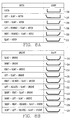
- the particular process within that operation must also be determined and attached to the node.
- This determination can be made by comparing the shape pattern for each operation with the shape patterns in Table 2 below:
- the scanning of this TABLE 2 list can occur sequentially or preferably a shapes pattern tree can be constructed as illustrated in Figure 7 which can be used to recognize the particular process of the operation.
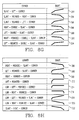
- the shapes represented by Figure 7 or TABLE 2 are illustrated in Figures 8A-8H.
- a conventional tree searching algorithm can be used to scan the tree looking for a match to each shape specified by a node.
- the tree of Figure 7 is designed for a preferred algorithm as described below.
- the preferred tree-search method takes four arguments: 1) Current-Node which determines where we are in the shapes tree; 2) Remaining-Surfaces designating all the surfaces that remain to be processed; 3) Surface-Sublist listing surfaces comprising the current shape; and 4) Rflag determining the contour direction.
- the tree search algorithm starts with the Current-Node set to the top level or root of the tree, namely, shapes-pattern is the object (see Figure 7).
- the Remaining-Surfaces will initially be all the surfaces that make up the contour of the part.
- the Surface-Sublist will be empty or nil and the reverse flag (Rflag) is set accordingly.
- the tree search routine gets a new surface from the front of the list of Remaining-Surfaces.
- the list initially contains the boundary surfaces for a particular node with the order being left, bottom and right. If the first surface is the left boundary (RSL) it is discarded.
- the contour direction (HS, VS, etc.) of the selected surface is obtained.
- the tree search algorithm makes a list of all of the immediate subclass children of the Current-Node. For each subclass child in the list, the algorithm compares the contour direction of the surface with the contour direction value of the child. If the contour directions are found to be the same, then we have found a match and we append the current surface to the end of the Surface-Sublist.
- a member child is the actual shape of the feature.
- the tree search returns this shape and unwinds the recursion. Else, there is no corresponding shape, either the shape knowledge base is incomplete or an invalid pattern has been entered (i.e., VS-UP, VS-DN).
- the algorithm returns failed and unwinds the recursion stack. For tp-9 the search process would identify the process as "left block” because the surface pattern is VS-DN.HS and for tp-3 it would identify a "notch" process because the pattern is VS-DN.HS.VS-UP.
- the identification of the particular process along with the type of material will identify the tool being used for the process because the process requires a particular type tool.
- Tool identification along with the material from the shape signature determines the depth of each rough machining pass based on tool manufacturer specifications.
- the depth of each pass along with the depth of material to be removed, specified in the tool description, is used to establish the number of roughing passes necessary to cut down approximately to the designated surface.
- the number of passes can be determined by dividing the depth of each cut by the material depth and subtracting one to allow for a finishing pass. If the division does not result in an integer a partial depth pass is determined from the remainder. It is also possible to not subtract one and make the last pass a partial depth cut to allow for a finishing pass. If the bottom boundary is a slant or rounded surface the end points of each pass must be adjusted to allow for a finishing pass.
- the process tree is scanned and for each notch process a determination is made to see if the notch is a candidate for a plunging process. If the width of the notch is less than one inch and the left and right sides of the notch are both vertical then the notch process is changed to a plunge notch process. If the notch cannot be completed by a plunging process the process planner 14 checks to see if the notch can be cut with existing tools by comparing tool tip size to the notch width. If the width of the notch is less than one inch and the left and/or right side of the notch are not vertical the process is changed to an impossible notch due to the unavailability of cutting tools. If the notch is not a candidate for a plunging process and has not been declared impossible because of the unavailability of tools, then this notch can be cut using the notch process previously designated by the shape tree search.
- machining operators are performed in a certain order with turndown or excess material removal coming first followed by blocks, notches and contouring.
- a facing process to establish a reference surface, is performed first and a threading operation comes after contouring.
- the process tree is scanned from top to bottom looking for turn down operations which are placed on the process list after the facing operation.
- the tree is then scanned from top to bottom adding left blocks to the list and then top to bottom adding right blocks. Blocks are cut in a preferred direction and the scanning for left and right blocks separately allows the machine to continue in a preferred direction and not turn the cutting head around. This improves machining efficiency.
- Next a scan for notches is performed to add them to the end of the list.
- Last the contouring and threading processes are added.
- the tools for adjacent levels of the tree with the same type of operation are compared and the process order is arranged to allow the minimum number of tool changes. For example, if level two uses tools 2 and 3 in processes tp-1 and tp-8 and level three uses tools 1 and 3 for processes tp-2 and tp-9 the processes would be ordered tp1-1, tp-8, tp-9 and tp-2.
- the tree is traversed from top to bottom breadthwise to create a sequential list of rough machining processes.
- a facing process in a turning operation is used to establish a reference surface from which all other surfaces are cut.
- the facing process is added to the front of the list of processes.
- a standard facing process is used in which the horizontal tool check surface at the start of the cut is the top boundary of the part being cut.
- the vertical clearance line in this process is the right boundary of the part being cut.
- the feed rate selected is determined by material being machined since the tool for facing is fixed for each machine. Ihe center line tool check surface is the bottom boundary of the part and the desired length is the finished length.
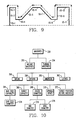
- a contouring pass requires that the part surfaces be treated as a continuous surface.
- a contour surface list as follows is created: VS-UP-1, HS-1, VS-DN-2, HS-2, VS-UP-3, HS-3, VS-UP-4, HS-4, VS-DN-5, HS-5, VS-DN-6. Because contour tools are designed to travel only in a single direction, some surfaces must be cut in a different direction. The contouring passes are created using the following rules:
- the above-algorithm when used on the part of Figure 9 will produce two contouring cuts with several contouring processes in each cut as illustrated by the dashed and solid arrowed lines.
- the original surface starting and ending surface coordinates are used to determine the actual tool movement cuts over the surface.
- the result is a tool designation and a corresponding list of cuts by the tool for the right and left direction contouring passes.
- the part finish which is part of the original shape signature will provide the speed at which the contouring tool moves across the part to obtain the desired finish smoothness.
- the tools and material are used to examine a table of feed speeds to determine the feed speeds for each process.
- Each tool has a preferred feed speed for a particular material as designated by and available from the tool manufacturer.
- the number of tools, feed speeds and rough stock geometry are used to determine a machine on which to machine the parts using a machine specification tree as illustrated in Figure 10.
- the leaves of the tree are compared with the machining parameters of the processes and the particular machine is selected based on a match to the particular characteristics.
- Each process frame includes a designation for the process, tool position turret, feed speed, number of passes, length of each pass and starting point.
- the starting point is on the top boundary (Y-coordinate) and is at the left or right boundary (X-coordinate) depending on the particular process selected.
- the ending point is the bottom boundary (Y-coordinate) and the left or right boundary (X-coordinate) depending on the direction of cut.
- the starting and ending plunge lines must be determined along with the number of plunges.
- the start point is determined and if there is no vertical surface through the start point a vertical line through the start point is designated as the starting plunge line.
- the end plunging line is set in the same manner.
- the depth of the plunge is the distance between the top and bottom boundaries and the number of plunges is determined from the region width by dividing the width with the plunge tool cut width. If the division does not result in an integer value the ending plunge line is adjusted accordingly.
- a header frame is created which specifies which turret holds which tool, the machine to be used and the type and size chuck necessary to hold the rough stock specified.
- the chuck size can be obtained from a table that lists chucks for the machines and the range of object sizes which the chuck will hold and the chuck type is specified by the type of material. For example, a hard material will allow a chuck with hard chuck surfaces. This information should also be provided in a look-up table based on chuck manufacturers recommendations.
- This header also includes other standard information such as drawing number which allow the part being manufactured to be identified.
- a part geometry frame is also created which creates a chuck mounting reference from which all tool positions are referenced.
- Each of the processes identified in Figures 8A-8H has an associated macro-program call which can be completed and called to generate the actual machine code for the different processes.
- the list of process frames is taken sequentially and used to complete the individual macrocalls to create a sequential list of processes which will complete the operations of the present invention.
- the standard facing process is used as previously discussed from which standard code is generated.
- the processes in Figures 8A-8H are created as macrocalls.
- the contouring process determines the directions of cut as described previously.
- the contour signature is then examined for primitive shapes.
- the start point for metal removal is the intersection of adjacent primitive shapes. From the start point, the primitive shape and direction, tool clearance lines, tool positioning, tool speed and a movement command from the start point are generated.
- the primitive shape specifies the feeds and speeds for the material as previously discussed.
- Each surface of the primitive shape defines a tool movement path over which the contouring tool is moved from the start point.
- the primitive shapes are contoured in the direction of tool movement previously determined.
- the end point of the tool movement is the opposite end of the primitive shape from the start point.
- a direction vector is determined which will move the tool away from all adjacent surfaces.
- the direction vector defines a tool withdrawal path and the speed is set at rapid traverse to clear the tool away from the part.
- the generalized macro-programs for the shapes of Figure 8A-8H and for the contouring cuts can be created by a numerical control part programmer of ordinary skill or obtained from a library of macro-programs available at most machine shops. For example, Westinghouse has an available macro-program library which includes the shapes illustrated in Figures 8A-8H.
- the sequential numerical control code is then provided to the code processor 18 which produces the machine code for the designated machine tool based on the macro-calls.
Landscapes
- Engineering & Computer Science (AREA)
- Human Computer Interaction (AREA)
- Manufacturing & Machinery (AREA)
- Physics & Mathematics (AREA)
- General Physics & Mathematics (AREA)
- Automation & Control Theory (AREA)
- Numerical Control (AREA)
Applications Claiming Priority (2)
| Application Number | Priority Date | Filing Date | Title |
|---|---|---|---|
| US07/179,685 US4928221A (en) | 1988-04-11 | 1988-04-11 | Part program generating system |
| US179685 | 1988-04-11 |
Publications (2)
| Publication Number | Publication Date |
|---|---|
| EP0337122A2 true EP0337122A2 (de) | 1989-10-18 |
| EP0337122A3 EP0337122A3 (de) | 1991-03-06 |
Family
ID=22657555
Family Applications (1)
| Application Number | Title | Priority Date | Filing Date |
|---|---|---|---|
| EP19890104258 Withdrawn EP0337122A3 (de) | 1988-04-11 | 1989-03-10 | Programmgenerierungssystem für ein Werkstück |
Country Status (6)
| Country | Link |
|---|---|
| US (1) | US4928221A (de) |
| EP (1) | EP0337122A3 (de) |
| JP (1) | JPH01316805A (de) |
| KR (1) | KR890016443A (de) |
| CN (1) | CN1037597A (de) |
| CA (1) | CA1320278C (de) |
Cited By (6)
| Publication number | Priority date | Publication date | Assignee | Title |
|---|---|---|---|---|
| FR2673302A1 (fr) * | 1991-02-26 | 1992-08-28 | Barlier Claude | Procede pour la creation et la realisation de pieces par c.a.o. et pieces ainsi obtenues. |
| EP0579841A1 (de) * | 1992-02-07 | 1994-01-26 | Fanuc Ltd. | Verfahren zur erstellung eines numerischen steuerungsprogrammes für winkelschnitte |
| EP0664186A1 (de) * | 1992-10-09 | 1995-07-26 | Omron Corporation | Verfahren und system zur bestimmung von bearbeitungsinformationen und verfahren und system zur bestimmung von bearbeitungsprozessinformationen |
| EP1413939A1 (de) * | 2002-10-24 | 2004-04-28 | Siemens Aktiengesellschaft | Programmier- und Betriebsverfahren für eine programmierbare industrielle Steuerung, insbesondere eine CNC-Steuerung |
| WO2005003872A1 (ja) | 2003-07-04 | 2005-01-13 | Mitsubishi Denki Kabushiki Kaisha | 自動プログラミング方法および装置 |
| US8005567B2 (en) | 2000-09-14 | 2011-08-23 | Airbus Operations Limited | Method and control system for generating machine tool control data |
Families Citing this family (54)
| Publication number | Priority date | Publication date | Assignee | Title |
|---|---|---|---|---|
| JPH01159705A (ja) * | 1987-12-17 | 1989-06-22 | Fanuc Ltd | 部品形状入力方法 |
| JPH0215304A (ja) * | 1988-07-04 | 1990-01-19 | Mitsubishi Electric Corp | 数値制御情報作成方法 |
| JPH0265945A (ja) * | 1988-08-31 | 1990-03-06 | Okuma Mach Works Ltd | 数値制御情報作成機能における加工方法の決定方式 |
| US5270940A (en) * | 1988-11-29 | 1993-12-14 | Fanuc Ltd | Contour configuration machining method |
| JPH0769733B2 (ja) * | 1989-01-26 | 1995-07-31 | オ−クマ株式会社 | 数値制御装置における塗潰し形状表示方式及びその装置 |
| JPH02287802A (ja) * | 1989-04-28 | 1990-11-27 | Okuma Mach Works Ltd | 数値制御情報作成装置 |
| US5117366A (en) * | 1989-06-28 | 1992-05-26 | Stong Jerald W | Automated carving system |
| US5307282A (en) * | 1989-09-22 | 1994-04-26 | Hewlett-Packard Company | Method of computer-aided prediction of collisions between objects including fabrication tools and parts to be fabricated |
| JP2752743B2 (ja) * | 1989-11-24 | 1998-05-18 | オ−クマ株式会社 | 数値制御情報作成機能における内径加工方法の決定方法及び装置 |
| JP2578241B2 (ja) * | 1990-04-05 | 1997-02-05 | 松下電器産業株式会社 | 自動プログラム作成装置 |
| JP2865213B2 (ja) * | 1990-06-26 | 1999-03-08 | オークマ株式会社 | 数値制御情報作成装置 |
| JP2849168B2 (ja) * | 1990-06-29 | 1999-01-20 | オ−クマ株式会社 | 数値制御情報作成装置 |
| JP2752787B2 (ja) * | 1990-11-29 | 1998-05-18 | オ−クマ株式会社 | 数値制御情報作成装置 |
| US5390320A (en) * | 1991-01-22 | 1995-02-14 | Grumman Aerospace Corporation | Automatically converting structured analysis tool database outputs into an integrated simulation model via transportable standardized metafile |
| JP2606460B2 (ja) * | 1991-02-21 | 1997-05-07 | 三菱電機株式会社 | Cad/cam装置のデータ生成方法 |
| US5293479A (en) * | 1991-07-08 | 1994-03-08 | Quintero Smith Incorporated | Design tool and method for preparing parametric assemblies |
| US5469361A (en) * | 1991-08-08 | 1995-11-21 | The Board Of Regents Acting For And On Behalf Of The University Of Michigan | Generic cell controlling method and apparatus for computer integrated manufacturing system |
| US6240332B1 (en) * | 1994-04-29 | 2001-05-29 | The Boeing Company | Tooling head controller |
| US6022132A (en) * | 1996-11-15 | 2000-02-08 | Thermwood Corporation | Method and apparatus for programming a CNC machine with a probe |
| US6442441B1 (en) | 1999-05-17 | 2002-08-27 | Ford Global Technologies, Inc. | Method of automatically generating and verifying programmable logic controller code |
| US7702491B2 (en) | 2000-09-29 | 2010-04-20 | Ford Global Technologies, Llc | Method of part flow model for programmable logic controller logical verification system |
| US6748283B2 (en) | 2000-09-29 | 2004-06-08 | Ford Motor Company | Method of using neutral event specification file for manufacturing line analysis |
| US20020133265A1 (en) * | 2001-03-14 | 2002-09-19 | Landers Diane M. | Horizontally structured manufacturing process modeling for concurrent product and process design |
| US20020133267A1 (en) * | 2001-03-14 | 2002-09-19 | Landers Diane M. | Enhancement to horizontally structured manufacturing process modeling |
| US20020133266A1 (en) * | 2001-03-14 | 2002-09-19 | Landers Diane M. | Horizontally structured manufacturing process modeling for alternate operations, large parts and charted parts |
| US20050044133A1 (en) * | 2001-07-27 | 2005-02-24 | Shinichiro Hashimoto | Information processing system for manufacturing building material, building material manufacturing method and facility, and building information circulating system |
| JP2003177811A (ja) * | 2001-12-12 | 2003-06-27 | Toyota Motor Corp | 設計支援装置及び方法 |
| KR100434025B1 (ko) * | 2001-12-31 | 2004-06-04 | 학교법인 포항공과대학교 | 스텝-엔씨(step-nc) 용 파트 프로그램을 자동생성하는 방법 |
| US7245984B2 (en) * | 2003-01-31 | 2007-07-17 | Delphi Technologies, Inc. | Horizontally structured manufacturing process modeling: exterior linked representational embodiment |
| JP2004336024A (ja) * | 2003-04-16 | 2004-11-25 | Tokyo Electron Ltd | 基板処理システム、基板処理方法及び該方法を実行するプログラム |
| CN100345142C (zh) * | 2003-12-05 | 2007-10-24 | 鸿富锦精密工业(深圳)有限公司 | 加工代码生成系统及方法 |
| US7536234B2 (en) * | 2004-02-09 | 2009-05-19 | Cadent Ltd. | Method and system for manufacturing a dental prosthesis |
| US7346478B2 (en) * | 2004-09-21 | 2008-03-18 | Ford Motor Company | Method of embedding tooling control data within mechanical fixture design to enable programmable logic control verification simulation |
| JP4569956B2 (ja) * | 2005-01-24 | 2010-10-27 | 東京エレクトロン株式会社 | 基板処理装置の復旧処理方法,基板処理装置,プログラム |
| CN100343770C (zh) * | 2005-09-14 | 2007-10-17 | 山东大学 | 一种数控车床的智能控制系统及其控制方法 |
| CN100458799C (zh) * | 2005-12-22 | 2009-02-04 | 同济大学 | 端拾器的自动优化设计方法 |
| US7761183B2 (en) * | 2006-02-13 | 2010-07-20 | Sullivan Douglas G | Methods and systems for producing numerical control program files for controlling machine tools |
| US7308327B2 (en) * | 2006-05-12 | 2007-12-11 | Ford Motor Company | Method of application protocol monitoring for programmable logic controllers |
| JP4256419B2 (ja) * | 2006-10-05 | 2009-04-22 | ファナック株式会社 | 旋削加工用のプログラム作成装置 |
| US7684892B2 (en) * | 2007-10-30 | 2010-03-23 | Gm Global Technology Operations, Inc. | Process for generating control sequence of operations |
| EP2189861B1 (de) * | 2008-11-24 | 2012-10-31 | Siemens Aktiengesellschaft | Verfahren zur Erstellung eines Teileprogramms |
| US8498733B2 (en) * | 2009-09-28 | 2013-07-30 | Hurco Companies, Inc. | Method and apparatus for reducing tool change operations |
| CN101920453B (zh) * | 2010-04-23 | 2012-04-25 | 中国第一重型机械股份公司 | 大型椭球体上的空间孔在数控镗铣床上加工方法 |
| US9389605B2 (en) | 2010-05-20 | 2016-07-12 | Mitsubishi Electric Corporation | Method of generating a numerical control program, apparatus for the same, and program for causing a computer to execute the method |
| CN102156440B (zh) * | 2011-03-01 | 2012-11-28 | 上海维宏电子科技股份有限公司 | 开槽机数控系统中实现开槽动作实时控制的方法 |
| US9566679B2 (en) * | 2013-03-15 | 2017-02-14 | Palo Alto Research Center Incorporated | Computer-implemented system and method for determining spatial locations of fixture element fixturing points on a part to be manufactured |
| US9235658B2 (en) * | 2013-03-15 | 2016-01-12 | Palo Alto Research Center Incorporated | Computer-implemented system and method for synthesizing a fixture layout for a part to be manufactured |
| CN103472763A (zh) * | 2013-09-03 | 2013-12-25 | 杭州威超机械设备有限公司 | 一种带有自动识别软件的无编程数控铣床 |
| CN103692351B (zh) * | 2013-11-26 | 2017-09-29 | 中山市锋凡机械设备有限公司 | 一种基于砂光设备的数控系统的家具零件抛光方法 |
| CN104698980B (zh) * | 2015-02-04 | 2017-06-30 | 上海电气电站设备有限公司 | 一种基于特征的数控立车参数化加工控制方法及系统 |
| TWM504260U (zh) * | 2015-04-09 | 2015-07-01 | Ningbo Techmation Co Ltd | 程式設計設備 |
| CN105426590B (zh) * | 2015-11-04 | 2021-06-29 | 中国电子科技集团公司第三十八研究所 | 一种机加工艺特征树及其构建方法 |
| CN107357273B (zh) * | 2017-07-05 | 2019-06-21 | 宁夏共享机床辅机有限公司 | 一种缸盖传送过程中的数据采集与防错的plc控制方法 |
| CN112764392B (zh) * | 2021-04-07 | 2021-08-03 | 成都飞机工业(集团)有限责任公司 | 一种用于防止数控加工中数控程序调用错误的方法 |
Citations (4)
| Publication number | Priority date | Publication date | Assignee | Title |
|---|---|---|---|---|
| EP0166783A1 (de) * | 1983-12-14 | 1986-01-08 | Fanuc Ltd. | Verfahren zur bestimmung der bearbeitungsstufen für selbsttätige programmierung |
| EP0185829A1 (de) * | 1984-12-27 | 1986-07-02 | Institut De Recherches De La Construction Navale | Verfahren zur Behandlung grosser Objekte |
| EP0198927A1 (de) * | 1984-10-26 | 1986-10-29 | Fanuc Ltd. | Numerisch gesteuerte datenerzeugung |
| EP0258897A2 (de) * | 1986-09-04 | 1988-03-09 | Sony Corporation | Verfahren und Anlage für die automatische Erzeugung von Werkzeugbahndaten für eine automatische Bearbeitungszentrale |
Family Cites Families (4)
| Publication number | Priority date | Publication date | Assignee | Title |
|---|---|---|---|---|
| US3534396A (en) * | 1965-10-27 | 1970-10-13 | Gen Motors Corp | Computer-aided graphical analysis |
| US3548173A (en) * | 1966-09-08 | 1970-12-15 | Ford Motor Co | Numerically controlled surface development method for preparing body contours |
| US4393450A (en) * | 1980-08-11 | 1983-07-12 | Trustees Of Dartmouth College | Three-dimensional model-making system |
| US4697240A (en) * | 1985-05-28 | 1987-09-29 | Modern Engineering Service Company | Method for making models using simultaneous construction and CAD/CAM techniques |
-
1988
- 1988-04-11 US US07/179,685 patent/US4928221A/en not_active Expired - Fee Related
-
1989
- 1989-03-10 EP EP19890104258 patent/EP0337122A3/de not_active Withdrawn
- 1989-04-04 CA CA000595684A patent/CA1320278C/en not_active Expired - Fee Related
- 1989-04-11 JP JP1091695A patent/JPH01316805A/ja active Pending
- 1989-04-11 KR KR1019890004838A patent/KR890016443A/ko not_active Application Discontinuation
- 1989-04-11 CN CN89102220A patent/CN1037597A/zh active Pending
Patent Citations (4)
| Publication number | Priority date | Publication date | Assignee | Title |
|---|---|---|---|---|
| EP0166783A1 (de) * | 1983-12-14 | 1986-01-08 | Fanuc Ltd. | Verfahren zur bestimmung der bearbeitungsstufen für selbsttätige programmierung |
| EP0198927A1 (de) * | 1984-10-26 | 1986-10-29 | Fanuc Ltd. | Numerisch gesteuerte datenerzeugung |
| EP0185829A1 (de) * | 1984-12-27 | 1986-07-02 | Institut De Recherches De La Construction Navale | Verfahren zur Behandlung grosser Objekte |
| EP0258897A2 (de) * | 1986-09-04 | 1988-03-09 | Sony Corporation | Verfahren und Anlage für die automatische Erzeugung von Werkzeugbahndaten für eine automatische Bearbeitungszentrale |
Non-Patent Citations (3)
| Title |
|---|
| 22nd ANNUAL MEETING & TECHINCAL CONFERENCE PROCEEDINGS vol. 1, May 1985, pages 17 - 26; HIDEMASA IIDA et al.: "CAM STATION AND PART DRAWING READER WITH 32-BIT MICROPROCESSORS" * |
| PATENT ABSTRACTS OF JAPAN vol. 10, no. 247 (P-490)(2303) 26 August 1986, & JP-A-61 75905 (MITSUBISHI ELECTRIC CORP.) 18 April 1986, * |
| ROBOTICS AND COMPUTER INTEGRATED MANUFACTURING. vol. 4, no. 1-2, 1988, HEADINGTON HILL HALL GB pages 49 - 62; GRUM J. ET AL.: "DESIGN OF THE DATABASE FOR CAD BASED ON GROUP TECHNOLOGY" * |
Cited By (14)
| Publication number | Priority date | Publication date | Assignee | Title |
|---|---|---|---|---|
| FR2673302A1 (fr) * | 1991-02-26 | 1992-08-28 | Barlier Claude | Procede pour la creation et la realisation de pieces par c.a.o. et pieces ainsi obtenues. |
| EP0585502A1 (de) * | 1991-02-26 | 1994-03-09 | LABORATOIRE ERIN.MP (Equipes de Recherche en Interface numérique Mécanique et Production) | Verfahren zur Herstellung und Gestaltung von Teilen mit C.A.D. und so erhaltene Teile |
| EP0579841A1 (de) * | 1992-02-07 | 1994-01-26 | Fanuc Ltd. | Verfahren zur erstellung eines numerischen steuerungsprogrammes für winkelschnitte |
| EP0579841A4 (en) * | 1992-02-07 | 1994-06-08 | Fanuc Ltd | Method of creating nc program for cutting corner |
| US5796618A (en) * | 1992-10-09 | 1998-08-18 | Omron Corporation | CAD system, method and medium for creating and encoding NC data based before and after workpiece models |
| EP0664186A4 (de) * | 1992-10-09 | 1995-09-20 | Verfahren und system zur bestimmung von bearbeitungsinformationen und verfahren und system zur bestimmung von bearbeitungsprozessinformationen. | |
| EP0664186A1 (de) * | 1992-10-09 | 1995-07-26 | Omron Corporation | Verfahren und system zur bestimmung von bearbeitungsinformationen und verfahren und system zur bestimmung von bearbeitungsprozessinformationen |
| US8005567B2 (en) | 2000-09-14 | 2011-08-23 | Airbus Operations Limited | Method and control system for generating machine tool control data |
| EP1413939A1 (de) * | 2002-10-24 | 2004-04-28 | Siemens Aktiengesellschaft | Programmier- und Betriebsverfahren für eine programmierbare industrielle Steuerung, insbesondere eine CNC-Steuerung |
| US7092783B2 (en) | 2002-10-24 | 2006-08-15 | Siemens Aktiengesellschaft | Programming and operating method for a programmable industrial controller, in particular a CNC controller |
| WO2005003872A1 (ja) | 2003-07-04 | 2005-01-13 | Mitsubishi Denki Kabushiki Kaisha | 自動プログラミング方法および装置 |
| EP1643330A1 (de) * | 2003-07-04 | 2006-04-05 | Mitsubishi Denki Kabushiki Kaisha | Automatisches programmierverfahren und einrichtung |
| EP1643330A4 (de) * | 2003-07-04 | 2006-10-18 | Mitsubishi Electric Corp | Automatisches programmierverfahren und einrichtung |
| US7457684B2 (en) | 2003-07-04 | 2008-11-25 | Mitsubishi Denki Kabushiki Kaisha | Automatic programming method and automatic programming device |
Also Published As
| Publication number | Publication date |
|---|---|
| KR890016443A (ko) | 1989-11-29 |
| CN1037597A (zh) | 1989-11-29 |
| EP0337122A3 (de) | 1991-03-06 |
| US4928221A (en) | 1990-05-22 |
| JPH01316805A (ja) | 1989-12-21 |
| CA1320278C (en) | 1993-07-13 |
Similar Documents
| Publication | Publication Date | Title |
|---|---|---|
| US4928221A (en) | Part program generating system | |
| US4513366A (en) | Menu programmed machine tool numerical controller with an interference checking function | |
| US5249135A (en) | Automatic design processing system for creating design processes for machining of parts | |
| EP0144426B1 (de) | Kontrollverfahren der werkzeuginterferenz | |
| US4704687A (en) | Method for constructioning tool approach and retraction paths from preset patterns | |
| EP0104542A1 (de) | Numerisch gesteuerte Bearbeitungsmethode | |
| KR20100068535A (ko) | 가공피쳐에 기반한 경험기반 nc 프로그래밍 및 공작물 가공 방법 | |
| EP0107147B1 (de) | Numerisch gesteuerter Prozess und nach diesem Prozess arbeitende Maschine | |
| US5113050A (en) | Method of creating coreless-machining nc data for wire cut electric discharge machining | |
| Kramer | Process planning for a milling machine from a feature-based design | |
| CN116224902A (zh) | 一种智能换刀决策控制系统 | |
| CN112305993B (zh) | 一种自动生成编程工艺的方法 | |
| JPS6267607A (ja) | 自動プログラミング装置 | |
| JP3844017B2 (ja) | レーザ加工における切断部品の切断順序決定方法 | |
| CN119126687A (zh) | 非标零件加工程序自动化生成方法及装置 | |
| JPH1173213A (ja) | 工具経路データ生成方法 | |
| JP4353689B2 (ja) | Cad/cam装置における加工経路情報の作成方法およびそのcad/cam装置 | |
| JPH0788743A (ja) | Nc旋盤におけるネジ切り加工方法 | |
| JP3116733B2 (ja) | Camシステム用加工軸方向決定装置 | |
| JPH05224721A (ja) | 3次元曲面形状加工方法 | |
| JPH10307615A (ja) | Cam用凹溝部位の加工経路自動生成方法 | |
| JP2544402B2 (ja) | 知識ベ―スツ―ルにおける条件文の判定方法 | |
| JP2003108207A (ja) | 荒加工方法 | |
| JPH0751988A (ja) | Ncデータ自動生成装置 | |
| JPH1199445A (ja) | 曲面加工装置及び方法 |
Legal Events
| Date | Code | Title | Description |
|---|---|---|---|
| PUAI | Public reference made under article 153(3) epc to a published international application that has entered the european phase |
Free format text: ORIGINAL CODE: 0009012 |
|
| AK | Designated contracting states |
Kind code of ref document: A2 Designated state(s): BE CH DE ES FR GB IT LI SE |
|
| PUAL | Search report despatched |
Free format text: ORIGINAL CODE: 0009013 |
|
| 17P | Request for examination filed |
Effective date: 19901228 |
|
| AK | Designated contracting states |
Kind code of ref document: A3 Designated state(s): BE CH DE ES FR GB IT LI SE |
|
| 17Q | First examination report despatched |
Effective date: 19930504 |
|
| STAA | Information on the status of an ep patent application or granted ep patent |
Free format text: STATUS: THE APPLICATION IS DEEMED TO BE WITHDRAWN |
|
| 18D | Application deemed to be withdrawn |
Effective date: 19930915 |