EP0107147B1 - Numerisch gesteuerter Prozess und nach diesem Prozess arbeitende Maschine - Google Patents
Numerisch gesteuerter Prozess und nach diesem Prozess arbeitende Maschine Download PDFInfo
- Publication number
- EP0107147B1 EP0107147B1 EP83110175A EP83110175A EP0107147B1 EP 0107147 B1 EP0107147 B1 EP 0107147B1 EP 83110175 A EP83110175 A EP 83110175A EP 83110175 A EP83110175 A EP 83110175A EP 0107147 B1 EP0107147 B1 EP 0107147B1
- Authority
- EP
- European Patent Office
- Prior art keywords
- workpiece
- shape
- working
- tool
- working path
- Prior art date
- Legal status (The legal status is an assumption and is not a legal conclusion. Google has not performed a legal analysis and makes no representation as to the accuracy of the status listed.)
- Expired - Lifetime
Links
Images


Classifications
-
- B—PERFORMING OPERATIONS; TRANSPORTING
- B23—MACHINE TOOLS; METAL-WORKING NOT OTHERWISE PROVIDED FOR
- B23Q—DETAILS, COMPONENTS, OR ACCESSORIES FOR MACHINE TOOLS, e.g. ARRANGEMENTS FOR COPYING OR CONTROLLING; MACHINE TOOLS IN GENERAL CHARACTERISED BY THE CONSTRUCTION OF PARTICULAR DETAILS OR COMPONENTS; COMBINATIONS OR ASSOCIATIONS OF METAL-WORKING MACHINES, NOT DIRECTED TO A PARTICULAR RESULT
- B23Q15/00—Automatic control or regulation of feed movement, cutting velocity or position of tool or work
- B23Q15/007—Automatic control or regulation of feed movement, cutting velocity or position of tool or work while the tool acts upon the workpiece
- B23Q15/08—Control or regulation of cutting velocity
- B23Q15/10—Control or regulation of cutting velocity to maintain constant cutting velocity between tool and workpiece
-
- G—PHYSICS
- G05—CONTROLLING; REGULATING
- G05B—CONTROL OR REGULATING SYSTEMS IN GENERAL; FUNCTIONAL ELEMENTS OF SUCH SYSTEMS; MONITORING OR TESTING ARRANGEMENTS FOR SUCH SYSTEMS OR ELEMENTS
- G05B19/00—Program-control systems
- G05B19/02—Program-control systems electric
- G05B19/18—Numerical control [NC], i.e. automatically operating machines, in particular machine tools, e.g. in a manufacturing environment, so as to execute positioning, movement or co-ordinated operations by means of program data in numerical form
- G05B19/416—Numerical control [NC], i.e. automatically operating machines, in particular machine tools, e.g. in a manufacturing environment, so as to execute positioning, movement or co-ordinated operations by means of program data in numerical form characterised by control of velocity, acceleration or deceleration
- G05B19/4163—Adaptive control of feed or cutting velocity
-
- G—PHYSICS
- G05—CONTROLLING; REGULATING
- G05B—CONTROL OR REGULATING SYSTEMS IN GENERAL; FUNCTIONAL ELEMENTS OF SUCH SYSTEMS; MONITORING OR TESTING ARRANGEMENTS FOR SUCH SYSTEMS OR ELEMENTS
- G05B19/00—Program-control systems
- G05B19/02—Program-control systems electric
- G05B19/18—Numerical control [NC], i.e. automatically operating machines, in particular machine tools, e.g. in a manufacturing environment, so as to execute positioning, movement or co-ordinated operations by means of program data in numerical form
-
- G—PHYSICS
- G05—CONTROLLING; REGULATING
- G05B—CONTROL OR REGULATING SYSTEMS IN GENERAL; FUNCTIONAL ELEMENTS OF SUCH SYSTEMS; MONITORING OR TESTING ARRANGEMENTS FOR SUCH SYSTEMS OR ELEMENTS
- G05B2219/00—Program-control systems
- G05B2219/30—Nc systems
- G05B2219/43—Speed, acceleration, deceleration control ADC
- G05B2219/43152—Feed in, transfer line, rapid traverse to work, grip speed
-
- G—PHYSICS
- G05—CONTROLLING; REGULATING
- G05B—CONTROL OR REGULATING SYSTEMS IN GENERAL; FUNCTIONAL ELEMENTS OF SUCH SYSTEMS; MONITORING OR TESTING ARRANGEMENTS FOR SUCH SYSTEMS OR ELEMENTS
- G05B2219/00—Program-control systems
- G05B2219/30—Nc systems
- G05B2219/49—Nc machine tool, till multiple
- G05B2219/49157—Limitation, collision, interference, forbidden zones, avoid obstacles
Definitions
- the present invention relates to a numerically controlled process (hereinafter referred to as an NC process) for processing an object (hereinafter referred to as the workpice) by controlling a processing machine e.g. a machine tool by means of a numerically controlling device (hereinafter referred to an an NC device), and is applicable to an NC working process for machining a workpiece according to a predetermined fashion, and relates to a machine operating according to the process.
- a numerically controlled process hereinafter referred to as an NC process
- a processing machine e.g. a machine tool
- an NC device numerically controlling device
- JP-A-5 716 4305 the contents of which are also to be found in EP-A-0 075 025.
- the numerically controlled machine method and apparatus in this prior art involves the determination of a plurality of boundary surfaces in a workpiece to be machined, each adjacent pair of boundary surfaces, for example an upper boundary surface and a lower boundary surface, defining a quantity of material to be removed from within the workpiece.
- the working tool cuts downwardly from the upper boundary surface until it reaches the lower boundary surface. It then cuts along said lower boundary surface until it reaches a point at which the tool is caused to travel upwardly to the first boundary surface at which stage a first section has been completely cut away from the workpiece and is removed.
- Each of these cutting movements is carried out at a slow speed.
- the now exposed lower boundary surface then becomes the new upper boundary surface and the adjacent boundary surface therebelow becomes the new lower boundary surface.
- the tool then carries out a rapid idle stroke across the free space created by the removal of the first cut-away section and the aforesaid cutting sequence is repeated to cause a second section between said new upper and new lower boundary surfaces to be completely cut away from the workpiece, and so on.
- a lower boundary surface may be so shaped as to define an upwardly directed hump so that a hump in the material will remain when the section above said lower boundary surface has been cut away.
- the new lower boundary surface that then exists below the now humped upper boundary surface cannot pass through the hump since otherwise the hump will be cut away at the next working stroke.
- the numerically controlled machine is so programmed that the cutting tool travels from a start point on the now exposed new upper boundary surface at slow speed along a new lower boundary surface until it finally rises up to a point where the plane of the new upper boundary surface extends through one side of the hump.
- the numerically controlled apparatus causes the working tool to move rapidly up and around the hump and to then descend rapidly until it reaches the point where the upper boundary surface extends through the other side of the hump. At this stage the working tool reverts to its slow cutting speed to continue its cutting action down to and along the new lower boundary surface extending away from said other side of the hump.
- an NC processing machine In a numerically controlled processing machine (hereinafter referred to as an NC processing machine) controlled by an NC device, the tool position with respect to the workpiece is controlled by numerical information corresponding to the tool position, and an operation or the like is performed under the control of the NC device, so that the workpiece is machined using calculated values or the like.
- an NC processing machine By means of such an NC processing machine, a workpiece can be easily machined into a complicated shape with high accuracy, and productivity can be improved.
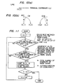
- an NC processing machine is consi- tuted, as shown in Figure 1 of the accompanying drawings, by an NC device 20 for operating upon numerical information commands externally inputted through a terminal 10, and a working machine 30 controlled using the values calculated in the NC device 20.
- the NC device 20 comprises an input section 21, an operation section 22 for processing commands from the input section 21, a memory section 23 for storing the results of processing in the operation section 22 or the instructions from the input section 21, a control section 24 for controlling the processing of the operation section 22, and an output section 25 for externally outputting processed values.
- a tool 31 is attached to a tool holder 32 which is in turn attached to a chuck of a spindle 33.
- the spindle 33 is rotated by a spindle motor 34 which is driven by a signal from the output section 25 of the NC device 20.
- a workpiece 40 is fixed onto a table 35 of the machine 30 by means of a jig or the like.
- reference numeral 36 designates a ball screw for moving the table 35 in the direction of the X-axis.
- the ball screw 36 is driven by an X-axis feed motor 38 through a gear box 37.
- the X-axis feed motor 38 is driven by a signal from the output section 25 of the NC device 20.
- mechanisms (not shown) are provided for moving the table 35 in the Y-axis and Z-axis directions respectively, and are driven by signals from the NC device 20.
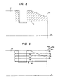
- a cylindrical workpiece 2 is supported at one end by a forward end portion 3a of a tail stock 3 and is positioned and fixed in a chuck 1 rotated about a rotary axis (Z-axis).
- a tool 5 for cutting the workpiece 2 is fixed onto a capstan rest 4.
- the capstan rest 4 is moved in the direction Z, as indicated by an arrow, whereby the workpiece 2 is machined.
- Fig. 3 the workpiece 2 is illustrated by a solid line, the final shape 6 of the workpiece 2 is shown by a two-dot chain line, and the cut portion 7 of the workpiece 2 is shown by oblique lines.
- the working path for obtaining the final shape 6 is shown and consists of working path elements I 1 , 1 2 , 1 3 , and 1 4.
- the tool 5 is caused to move along the working path in the order of the original point Q 0 ⁇ a path m 1 ⁇ a first working start point Q, ⁇ working path element I, ⁇ a second working start point Q 2 -j working path element 1 2 a a third working start point Q 3 ⁇ working path element 1 3 ⁇ a fourth working start point Q 4 ⁇ working path element 1 4 ⁇ a path m 2 ⁇ the original point Q o , to thereby obtain the final worked shape 6.
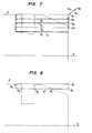
- a workpiece 2 which has been cut in advance is shown, and in Fig. 6, the working path for obtaining a final shape 6 is illustrated.
- the same working path as that in Fig. 4 is set in accordance with the desired final shape even for a preworked workpiece.
- the working paths I 1 , 1 2 , 1 3 and 1 4 are set without regard to the shape of the workpiece before machining, and therefore in this case the tool 5 is caused to move at a relatively slow speed along parts of the working path where material of the workpiece 2 does not exist, resulting in lost working time.
- the present invention is intended to overcome the above-mentioned problem in the prior art, and an object of the present invention is to provide an NC working process in which the moving speed of a tool over a range of non-working movement of the tool is increased relative to the moving speed during normal working, in accordance with the shape of the workpiece before machining, thereby to reduce the time wasted due to non-working movement of the tool.
- a process for attaining the above-mentioned object is, according to the present invention, as defined in the accompanying Claim 1.
- a numerically controlled processing machine for attaining the above-mentioned object is, according to the present invention, as defined in the accompanying Claim 6.
- Fig. 7 shows the working path and the speed of the tool. This embodiment is setto obtain the final shape 6 for the preworked workpiece 2 as shown in Fig. 5.
- the working path per se of Fig. 7 is quite the same as that shown in Fig. 6, but the moving speed of the tool is different. That is, in Fig. 7, the working path indicated by a solid line shows a range in which cutting is actually effected into the workpiece (an actual working region) and in which the tool is fed at a relatively slow cutting speed, while the dotted line indicates a range in which the tool is idly moved without cutting the workpiece (an idle or non-working movement region) and in which the tool is moved at a high speed.
- Fig. 8 shows a method of distinguishing the actual working region and the idle movement region from one another.
- data as to the shape of the workpiece before machining is inputted in advance.
- the data on the shape of the workpiece before machining and a working path segment (represented by I 1 in Fig. 8) obtained on the basis of the finished shape 6 of the workpiece are compared with each other so as to first obtain the points of intersection therebetween.
- P 1 , P 2 , P 3 , and P 4 represent the respective points of intersection. Since the working start point Q, is outside the workpiece shape, the path from the working start point Q, to the point of intersection P, is an idle movement region and the tool is caused to move at a high speed in this region.
- the path from the point of intersection P, to the point of intersection P 2 is an actual working region, and therefore the tool is caused to move at a low cutting speed.
- the path from the point of intersection P 2 to the point of intersection P 3 is an idle movement region, and therefore the tool is caused to move at a high speed.
- the path from the point of intersection P 3 to the point of intersection P 4 is an actual working region and therefore the tool is caused to move at a low cutting speed. This process is repeated, and the idle movement regions and actual working regions are also obtained for the other working path segments 1 2 , 1 3 and 1 4 , to thereby switch the tool feed speed for the respective regions.
- Fig. 9 is a flowchart showing the processing procedure when the above-described NC working process according to the present invention is used.
- the shape of the workpiece before working is inputted (step 100), which is the information relating to the shape of the path from the start point to the end point at the inner or outer periphery of the workpiece as represented by line segments and/or circular arcs. More particularly, in the case of a line segment, the coordinate values X and Z of the end point of the line segment are set as shown in Fig. 10(a), and in the case of a circular arc, the coordinate values I and J of the center of the arc, the coordinate values X and Z of the end point, the value of the radius and the direction of rotation CW or CCW are set as shown in Fig. 10(b). The figure determined by these values is the workpiece shape and these values are inputted as the information on the workpiece shape.
- step 101 the desired finished shape of the workpiece is inputted (step 101).
- the finish shape is expressed by line segments and/or circular arcs, and the information thereon is inputted.
- the working path for the tool is automatically determined on the basis of the finished shape (step 102). This is performed such that an LAP path is automatically calculated on the basis of the preset finished shape, the cutting start point and the amount of cutting, and the working path for machining the workpiece at a position shifted from the cutting start point by the amount of cutting is formed and extracted.
- the data on the shape of the workpiece before machining and the working path are compared with each other to obtain the points of intersection therebetween (step 103).
- the working path causes the tool to laterally cut the workpiece in the Z-direction from the cutting position and therefore it will suffice to judge only whether the X coordinate value of the cutting position intersects the workpiece shape or not.
- the workpiece shape is a combination of line segments and/or circular arcs and therefore it will suffice to judge whether each of the line segments and/or circular arcs has a point of intersection at this X coordinate value.
- This operation may be expressed by a flowchart as shown in Fig. 11.
- step 105 On the basis of this step, when there exists a point of intersection, judgement is made as to whether or not the working start point is outside the workpiece shape (step 105).
- the first tool feed speed is set at the high speed, while in the case where it is inside the work shape, the first tool feed speed is set at the low speed (step 107). Thereafter, every time the tool has reached a point of intersection, the tool feed speed is alternately switched from high speed to low speed or vice versa (step 108).
- the judgement as to whether the tool is outside the workpiece shape or not is performed in a manner such that if the tool is on the (+) side in the X-direction from the workpiece shape in working the outer periphery of the workpiece, or on the (-) side in working the inner periphery, it is judged that the tool is outside the workpiece shape, while if the tool is on the (-) side ((+) side) in the X-direction from the workpiece shape in working the outer (inner) periphery of the workpiece, respectively, it is judged that the tool is inside the workpiece shape.
- the tool feed speed may be set to several times the cutting speed, or alternatively may be set to another suitable value.
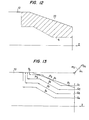
- Fig. 12 and 13 show another embodiment of the present invention in which the working path of profile cutting is formed on the basis of the finished shape of the workpiece.
- Fig. 12 shows an example of a workpiece 12 which has been cut in advance, and the final working shape 6 is indicated by a two-dot chain line.
- the working path in this case consists of working path elements I 1 , 1 2 , 1 3 and 1 4 as shown in Fig. 13.
- the tool 5 moves in the order of the working original point Q 0 ⁇ a path m, -> a first working start point Q 1 ⁇ a working path element I, ⁇ a second working start point Q 2 ⁇ a working path element 1 2 ⁇ a third working start point Q 3 ⁇ a working path element 1 3 ⁇ a fourth working start point Q 4 ⁇ a working path element 1 4 - a path m 2 ⁇ the original point Q o to thereby obtain the final shape 6.
- the working path is determined regardless of the shape of the workpiece before machining and therefore the idle movement of the tool increases, resulting in a waste of usable working time.
- the shape of the workpiece is inputted in advance and the data on the inputted shape is compared with the above-mentioned working path so that a judgement is made as to whether the tool is outside the above-mentioned workpiece shape or not, so as to cause the tool to move at a high speed when the tool is outside the workpiece shape.
- the working path as indicated by a solid line in Fig. 13, includes a range in which cutting is actually effected on the workpiece (an actual working region) and in which the tool is fed at the relatively slow cutting speed.
- the dotted line indicates the range in which the tool is idly moved without cutting the workpiece (an idle movement region) and in which the tool is caused to move at a high speed.
- the actual working region and the idle movement region are distinguished from each other as follows.
- the data as to the shape of the workpiece 12 before machining is inputted in advance.
- the data on the shape before working and the working path (represented by I, in Fig. 13) obtained on the basis of the finished shape 6 of the workpiece 12 are compared with each other so as to first obtain the points of intersection therebetween.
- P 1 , P 2 , P 3 and P 4 represent the respective points of intersection. Since the working start point Q, is outside of the workpiece shape, the path from the working start point Q, to the point of intersection P, is an idle movement region and the tool is caused to move at a high speed in this region.
- the path from the point of intersection P, to the point of intersection P 2 is an actual working region and therefore the tool is caused to move at a low cutting speed.
- the path from the point of intersection P 2 to the point of intersection P 3 is an idle movement region and therefore the tool is caused to move at high speed.
- the path from the point of intersection P 3 to the point of intersection P 4 is again an actual working region and therefore the tool is caused to move at the low cutting speed. This process is repeated in subsequent idle movement and actual working regions with respect to the other working paths 1 2 , 1 3 and 1 4 , to thereby switch the tool feed speed for the respective regions.
Landscapes
- Engineering & Computer Science (AREA)
- Human Computer Interaction (AREA)
- Manufacturing & Machinery (AREA)
- Physics & Mathematics (AREA)
- General Physics & Mathematics (AREA)
- Automation & Control Theory (AREA)
- Mechanical Engineering (AREA)
- Numerical Control (AREA)
Claims (6)
Applications Claiming Priority (4)
| Application Number | Priority Date | Filing Date | Title |
|---|---|---|---|
| JP178708/82 | 1982-10-12 | ||
| JP57178708A JPS5968011A (ja) | 1982-10-12 | 1982-10-12 | 数値制御加工方式 |
| JP17870982A JPS5968012A (ja) | 1982-10-12 | 1982-10-12 | 数値制御加工方式 |
| JP178709/82 | 1982-10-12 |
Publications (3)
| Publication Number | Publication Date |
|---|---|
| EP0107147A2 EP0107147A2 (de) | 1984-05-02 |
| EP0107147A3 EP0107147A3 (en) | 1986-01-08 |
| EP0107147B1 true EP0107147B1 (de) | 1990-09-19 |
Family
ID=26498796
Family Applications (1)
| Application Number | Title | Priority Date | Filing Date |
|---|---|---|---|
| EP83110175A Expired - Lifetime EP0107147B1 (de) | 1982-10-12 | 1983-10-12 | Numerisch gesteuerter Prozess und nach diesem Prozess arbeitende Maschine |
Country Status (4)
| Country | Link |
|---|---|
| US (1) | US4698573A (de) |
| EP (1) | EP0107147B1 (de) |
| KR (1) | KR880001305B1 (de) |
| DE (1) | DE3381889D1 (de) |
Families Citing this family (10)
| Publication number | Priority date | Publication date | Assignee | Title |
|---|---|---|---|---|
| US5206813A (en) * | 1988-11-15 | 1993-04-27 | Kabushiki Kaisha Okuma Tekkosho | Graphic display method for numerical controller |
| US5600759A (en) * | 1989-03-20 | 1997-02-04 | Fanuc Ltd. | Robot capable of generating patterns of movement path |
| US5204810A (en) * | 1989-03-24 | 1993-04-20 | Fanuc Ltd. | Nc sentence creation system |
| US5126645A (en) * | 1989-09-30 | 1992-06-30 | Kabushiki Kaisha Toshiba | Grinder robot |
| JP2642203B2 (ja) * | 1989-12-04 | 1997-08-20 | オ−クマ株式会社 | 数値制御情報作成装置 |
| US5107436A (en) * | 1990-04-06 | 1992-04-21 | Northern Research & Engineering Corp. | Method for generating a tool course for a cutting tool |
| JPH04229307A (ja) * | 1990-12-27 | 1992-08-18 | Fanuc Ltd | Ncデータ作成方法 |
| EP0495147A1 (de) * | 1991-01-18 | 1992-07-22 | Siemens Aktiengesellschaft | Verfahren zur Bahnkorrektur bei numerisch gesteuerten Maschinen |
| EP0511814A1 (de) * | 1991-05-01 | 1992-11-04 | British United Shoe Machinery Limited | Fortschreitende Betriebskontrolle eines Werkzeuges entlang eines bestimmten Weges |
| IL126752A0 (en) * | 1997-03-15 | 1999-08-17 | Makino Milling Machine | Machine tool control apparatus |
Citations (3)
| Publication number | Priority date | Publication date | Assignee | Title |
|---|---|---|---|---|
| US4350941A (en) * | 1980-09-19 | 1982-09-21 | Ford Motor Company | Control for automatic machine tool drive |
| EP0075025A1 (de) * | 1981-04-01 | 1983-03-30 | Fanuc Ltd. | Numerisch gesteuertes werkzeug, sowie vorrichtung |
| US4415977A (en) * | 1979-06-30 | 1983-11-15 | Fujitsu Fanuc Limited | Method of constant peripheral speed control |
Family Cites Families (4)
| Publication number | Priority date | Publication date | Assignee | Title |
|---|---|---|---|---|
| US4033206A (en) * | 1974-07-11 | 1977-07-05 | Daihatsu Motor Co., Ltd. | Numerically controlled machine tool |
| US4477754B1 (en) * | 1976-07-06 | 1995-03-21 | Hurco Co Inc | Interactive machining system |
| US4445182A (en) * | 1979-10-02 | 1984-04-24 | Daihatsu Motor Company, Limited | Method of control of NC machine tools |
| EP0064994A4 (de) * | 1980-11-25 | 1984-11-16 | Commw Of Australia | Gestaltung von umrissen. |
-
1983
- 1983-10-11 KR KR1019830004806A patent/KR880001305B1/ko not_active Expired
- 1983-10-12 US US06/541,210 patent/US4698573A/en not_active Expired - Lifetime
- 1983-10-12 DE DE8383110175T patent/DE3381889D1/de not_active Expired - Lifetime
- 1983-10-12 EP EP83110175A patent/EP0107147B1/de not_active Expired - Lifetime
Patent Citations (3)
| Publication number | Priority date | Publication date | Assignee | Title |
|---|---|---|---|---|
| US4415977A (en) * | 1979-06-30 | 1983-11-15 | Fujitsu Fanuc Limited | Method of constant peripheral speed control |
| US4350941A (en) * | 1980-09-19 | 1982-09-21 | Ford Motor Company | Control for automatic machine tool drive |
| EP0075025A1 (de) * | 1981-04-01 | 1983-03-30 | Fanuc Ltd. | Numerisch gesteuertes werkzeug, sowie vorrichtung |
Also Published As
| Publication number | Publication date |
|---|---|
| US4698573A (en) | 1987-10-06 |
| DE3381889D1 (de) | 1990-10-25 |
| KR840006456A (ko) | 1984-11-30 |
| KR880001305B1 (ko) | 1988-07-22 |
| EP0107147A3 (en) | 1986-01-08 |
| EP0107147A2 (de) | 1984-05-02 |
Similar Documents
| Publication | Publication Date | Title |
|---|---|---|
| US20140200707A1 (en) | Numerical controller having function of re-machining thread cutting cycle | |
| EP0107147B1 (de) | Numerisch gesteuerter Prozess und nach diesem Prozess arbeitende Maschine | |
| US4739489A (en) | Area cutting method | |
| EP0323517B1 (de) | Profilierungsverfahren | |
| EP0104542B1 (de) | Numerisch gesteuerte Bearbeitungsmethode | |
| KR930010589B1 (ko) | 절삭공구의 정지 제어장치 | |
| KR860002075B1 (ko) | 수치제어 가공방식 | |
| JP6408040B2 (ja) | 数値制御装置 | |
| US4891487A (en) | Electrode return control for electric spark machine | |
| JPH0253161B2 (de) | ||
| JPH04269152A (ja) | 数値制御工作機械における内円切削制御装置 | |
| CN106814689A (zh) | 数值控制装置 | |
| EP0301097B1 (de) | Verfahren mit numerischer steuerung | |
| JPH04764B2 (de) | ||
| JPS58171242A (ja) | 適応制御機能付nc装置 | |
| JPH06246586A (ja) | 数値制御プログラム作成装置 | |
| JPH0421206B2 (de) | ||
| KR0151088B1 (ko) | 선반용 자동 공구궤적 생성프로그램을 이용한 대상물 가공방법 | |
| KR100206135B1 (ko) | 가공물 절삭 제어방법 | |
| JPH01205954A (ja) | 工作機械の工具径路自動決定装置 | |
| JPH09314410A (ja) | 数値制御装置を用いた座ぐり加工方法 | |
| JPS5968012A (ja) | 数値制御加工方式 | |
| JP2612364B2 (ja) | 数値制御装置 | |
| EP0397884A1 (de) | Bearbeitungssystem für bahnkonturen | |
| JPH04291605A (ja) | 干渉防止機能を持つ加工装置 |
Legal Events
| Date | Code | Title | Description |
|---|---|---|---|
| PUAI | Public reference made under article 153(3) epc to a published international application that has entered the european phase |
Free format text: ORIGINAL CODE: 0009012 |
|
| AK | Designated contracting states |
Designated state(s): DE FR GB IT |
|
| PUAL | Search report despatched |
Free format text: ORIGINAL CODE: 0009013 |
|
| AK | Designated contracting states |
Designated state(s): DE FR GB IT |
|
| 17P | Request for examination filed |
Effective date: 19860304 |
|
| 17Q | First examination report despatched |
Effective date: 19870429 |
|
| GRAA | (expected) grant |
Free format text: ORIGINAL CODE: 0009210 |
|
| AK | Designated contracting states |
Kind code of ref document: B1 Designated state(s): DE FR GB IT |
|
| REF | Corresponds to: |
Ref document number: 3381889 Country of ref document: DE Date of ref document: 19901025 |
|
| ET | Fr: translation filed | ||
| ITF | It: translation for a ep patent filed | ||
| PLBI | Opposition filed |
Free format text: ORIGINAL CODE: 0009260 |
|
| 26 | Opposition filed |
Opponent name: GILDEMEISTER AKTIENGESELLSCHAFT Effective date: 19910613 |
|
| PGFP | Annual fee paid to national office [announced via postgrant information from national office to epo] |
Ref country code: FR Payment date: 19921027 Year of fee payment: 10 |
|
| ITTA | It: last paid annual fee | ||
| PLBN | Opposition rejected |
Free format text: ORIGINAL CODE: 0009273 |
|
| STAA | Information on the status of an ep patent application or granted ep patent |
Free format text: STATUS: OPPOSITION REJECTED |
|
| 27O | Opposition rejected |
Effective date: 19940128 |
|
| PG25 | Lapsed in a contracting state [announced via postgrant information from national office to epo] |
Ref country code: FR Effective date: 19940630 |
|
| REG | Reference to a national code |
Ref country code: FR Ref legal event code: ST |
|
| REG | Reference to a national code |
Ref country code: GB Ref legal event code: 746 Effective date: 19951107 |
|
| PGFP | Annual fee paid to national office [announced via postgrant information from national office to epo] |
Ref country code: GB Payment date: 20011010 Year of fee payment: 19 |
|
| REG | Reference to a national code |
Ref country code: GB Ref legal event code: IF02 |
|
| PG25 | Lapsed in a contracting state [announced via postgrant information from national office to epo] |
Ref country code: GB Free format text: LAPSE BECAUSE OF NON-PAYMENT OF DUE FEES Effective date: 20021012 |
|
| PGFP | Annual fee paid to national office [announced via postgrant information from national office to epo] |
Ref country code: DE Payment date: 20021017 Year of fee payment: 20 |
|
| GBPC | Gb: european patent ceased through non-payment of renewal fee |
Effective date: 20021012 |