EP0337079A2 - Procédé et dispositif d'enroulage de bandes de matériau, notamment de bandes de papier ou de carton - Google Patents
Procédé et dispositif d'enroulage de bandes de matériau, notamment de bandes de papier ou de carton Download PDFInfo
- Publication number
- EP0337079A2 EP0337079A2 EP89102730A EP89102730A EP0337079A2 EP 0337079 A2 EP0337079 A2 EP 0337079A2 EP 89102730 A EP89102730 A EP 89102730A EP 89102730 A EP89102730 A EP 89102730A EP 0337079 A2 EP0337079 A2 EP 0337079A2
- Authority
- EP
- European Patent Office
- Prior art keywords
- roller
- ejection
- support roller
- winding
- ejection surface
- Prior art date
- Legal status (The legal status is an assumption and is not a legal conclusion. Google has not performed a legal analysis and makes no representation as to the accuracy of the status listed.)
- Granted
Links
- 238000004804 winding Methods 0.000 title claims abstract description 46
- 239000000463 material Substances 0.000 title claims description 7
- 238000000034 method Methods 0.000 title claims description 5
- 239000011111 cardboard Substances 0.000 title claims description 4
- 239000011087 paperboard Substances 0.000 title claims description 4
- 238000003780 insertion Methods 0.000 claims description 12
- 230000037431 insertion Effects 0.000 claims description 12
- 239000000123 paper Substances 0.000 claims 1
- 238000010276 construction Methods 0.000 description 1
Images


Classifications
-
- B—PERFORMING OPERATIONS; TRANSPORTING
- B65—CONVEYING; PACKING; STORING; HANDLING THIN OR FILAMENTARY MATERIAL
- B65H—HANDLING THIN OR FILAMENTARY MATERIAL, e.g. SHEETS, WEBS, CABLES
- B65H18/00—Winding webs
- B65H18/08—Web-winding mechanisms
- B65H18/14—Mechanisms in which power is applied to web roll, e.g. to effect continuous advancement of web
- B65H18/20—Mechanisms in which power is applied to web roll, e.g. to effect continuous advancement of web the web roll being supported on two parallel rollers at least one of which is driven
-
- B—PERFORMING OPERATIONS; TRANSPORTING
- B65—CONVEYING; PACKING; STORING; HANDLING THIN OR FILAMENTARY MATERIAL
- B65H—HANDLING THIN OR FILAMENTARY MATERIAL, e.g. SHEETS, WEBS, CABLES
- B65H19/00—Changing the web roll
- B65H19/22—Changing the web roll in winding mechanisms or in connection with winding operations
- B65H19/30—Lifting, transporting, or removing the web roll; Inserting core
-
- B—PERFORMING OPERATIONS; TRANSPORTING
- B65—CONVEYING; PACKING; STORING; HANDLING THIN OR FILAMENTARY MATERIAL
- B65H—HANDLING THIN OR FILAMENTARY MATERIAL, e.g. SHEETS, WEBS, CABLES
- B65H2301/00—Handling processes for sheets or webs
- B65H2301/40—Type of handling process
- B65H2301/41—Winding, unwinding
- B65H2301/417—Handling or changing web rolls
- B65H2301/4171—Handling web roll
- B65H2301/4172—Handling web roll by circumferential portion, e.g. rolling on circumference
-
- B—PERFORMING OPERATIONS; TRANSPORTING
- B65—CONVEYING; PACKING; STORING; HANDLING THIN OR FILAMENTARY MATERIAL
- B65H—HANDLING THIN OR FILAMENTARY MATERIAL, e.g. SHEETS, WEBS, CABLES
- B65H2404/00—Parts for transporting or guiding the handled material
- B65H2404/40—Shafts, cylinders, drums, spindles
- B65H2404/42—Arrangement of pairs of drums
- B65H2404/421—Bed arrangement, i.e. involving parallel and spaced drums, e.g. arranged horizontally for supporting a roll to be wound or unwound
- B65H2404/4213—Bed arrangement, i.e. involving parallel and spaced drums, e.g. arranged horizontally for supporting a roll to be wound or unwound the drums having different diameter
Definitions
- the invention relates to a method for winding webs of material, in particular paper or cardboard webs, onto cores according to the preamble of patent claim 1 and a carrier roller winding machine according to the preamble of patent claim 2.
- roll ejection and sleeve insertion devices which eject the full rolls from the roll bed when a roll is changed and insert new sleeves into the roll bed.
- a generic method and a support roller winding machine with the features of the preamble of claim 2 is described in DE-PS 31 51 256. There, the roller ejection and the sleeve insertion device are structurally separate and each can be pivoted separately in the direction of the support roller bed.
- a carrier roller winding machine with a combined ejection and insertion device according to the preamble of claim 5 is described, which consists of an ejection bar and a collet, which are attached to a common lever and so together from the outside a support roller can be pivoted to the roller bed.
- the ejection surface of the ejection bar extends approximately radially to the pivoted support roller. It ends at a distance from the support roller that is larger than the sleeve diameter so that the collet integrated in the ejection bar can take up the sleeves through the space and insert them into the support roller bed.
- the ejection and insertion device of this winding machine additionally has a holding device between the clamping jaws of the collet, with which the winding sleeves can be lowered onto the support rollers without twisting after swiveling over the roller bed.
- a disadvantage of all these known carrier roller winding machines is that the winding rollers must have a minimum diameter so that they can be ejected from the ejection bar, since the winding rollers must be pushed up to the apex line of the second carrier roller during ejection.
- the minimum diameter is more than twice as large as the distance between the lower end of the ejecting surface of the ejecting bar and the supporting roller, which is pivoted, for the function of the inserting device.
- rollers In practice, it can happen for various reasons that a complete set of rollers must be declared as a scrap and removed from the roller bed shortly after the winding. For rolls that have not yet reached the minimum diameter, they must then be lifted out of the roller bed manually. Since the rollers already have a considerable weight, this places a considerable burden on the operating personnel.
- the invention has for its object to provide a generic method with which wound rolls with a small diameter can be removed from the roll bed.
- Another object is to provide a generic support roller winding machine which is capable of removing coiled rolls with a small diameter from the roll bed.
- the first object is achieved with the measures of claim 1.
- the second object is achieved both with the features of claim 2 and with the features of claim 5.
- the ejecting and inserting device according to claim 5 can be converted to eject rolls with a small diameter, at the same time protecting the sleeve inserting elements against damage.
- the elastically attachable ejection surface according to claims 3, 4 and 10 ensures constant contact at approximately the same pressure between the ejection surface, the pinched roller and the support roller.
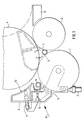
- the carrier roller winding machine has two carrier rollers 1, 2, between which a roller bed 3 is formed, in which the winding rollers 4 rest on the carrier rollers 1, 2 during winding.
- the material web which is divided lengthways into individual webs, preferably a paper or cardboard web, is guided from below - deflected by the support roller 1 - between the support rollers 1, 2 into the support roller bed 3 and wound onto sleeves 5 aligned.
- Such double carrier roller winding machines are known, so design details are not discussed.
- a lever 6 is pivotally articulated coaxially to the axis of rotation of the support roller 1.
- the pivoting movement is carried out by means of an adjusting unit - in the present example a hinged piston-cylinder unit 7.
- the piston-cylinder unit 7 is designed to be somewhat flexible in both pivoting directions, so that the levers 6 are elastically coupled within limits.
- the free ends of the levers 6 are angled in the direction of the roller bed 3 and carry a roller ejection and sleeve insertion device 8, which is described in more detail below.
- an ejection bar 9 extending across the working width is attached.
- the ejection bar 9 is fastened to additional swivel arms 10 which are articulated on the levers 6 and which can be swiveled relative to the levers 6 in the direction of the supporting roller 1 by means of a piston-cylinder unit 11.
- the ejection bar 9 is firmly connected to the levers 6.
- the ejection bar 9 is used to eject a finished winding roller 4 via the support roller 2 onto a lowering platform 12. Its ejection surface 13 facing the support roller 2 is shaped approximately to match the circumference of a winding roller 4 and extends approximately radially to the support roller 1. 1-3, dash-dotted lines), the ejection surface 13 extends to the vicinity of the apex line of the support roller 2.
- the roller ejection and sleeve insertion device 8 contains a collet 14 for inserting new sleeves 5 into the roller bed 3, the clamping jaws of which are located in the area between the ejection bar 9 and the supporting roller 1.
- the collet 14 is attached to the angled part of the lever 6.
- the construction of such collets is known and e.g. described in DE-OS 35 27 377 or in DE-PS 29 48 877.
- the ejection surface 13 is extended to the area of the collet 14 to such an extent that when the swivel arm 10 (FIG. 2) is swiveled forward, it extends to just before the support roller 1.
- the swivel arm 10 (FIG. 2) is swiveled forward, it extends to just before the support roller 1.
- a machine-wide extension plate 15 is articulated on the end of the ejection surface 13 facing the support roller 1 about a pivot axis 16 parallel to the support roller axes.
- the sheet 15 can be pivoted back so far that it bears against the ejection surface 13 and thus releases the required space for the supporting roller 1 for inserting sleeves 5.
- the sheet 15 can be folded down to just before the support roller 1 in order to extend the ejection surface 13 to the support roller 1.
- the double carrier roll winding machine described above works as follows:
- empty sleeves 5 are placed in the chuck 14 in the waiting position and held by the latter.
- the ejection bar 9 is pivoted in the direction of the roll bed 3 and thereby pushes the full roll 4 from the roll bed 3 onto the lowering platform 12.
- the collet 14 with the empty sleeves 5 is simultaneously moved in the direction of the roll bed 3, where the tongs 14 opens and the sleeves 5 are placed on the support rollers 1, 2.
- the support rollers 1, 2 are set into a rotational movement for winding up.
- rollers 17 with such a small diameter have to be removed from the roller bed 3, in which the ejection and insertion device 8 is no longer functional in the manner described above, the swivel arms (10) are in the waiting position relative to the levers 6 in the direction of the roller bed 3 pivoted ( Figure 2) or the extension plate 15 is folded down towards the support roller 1. In this way, a surface extending to the support roller 1 is created in each case.
- the levers 6 with the piston-cylinder unit 7 are then pivoted in the direction of the roller bed 3 until the ejection surface 13 (FIG. 2) or the extension plate 15 (FIG. 3) on the Rollers 17 abuts and presses them against the support roller 2.
- the support roller 2 is now driven clockwise (arrow 18).
- the rollers 17 are conveyed up between the support roller 2 and the ejection surface 13 or the extension plate 15 up to the apex line of the support roller 2, from where they roll automatically onto the lowering platform 12.
- the roller ejection device 8 and thus the ejection surface 13 is designed to be flexible in both pivoting directions, so that the contact between the support roller 2, the rollers 17 and the ejection surface 13 is constantly maintained with approximately the same pressure.
Landscapes
- Replacement Of Web Rolls (AREA)
- Winding Of Webs (AREA)
- Packaging Of Special Articles (AREA)
Priority Applications (1)
| Application Number | Priority Date | Filing Date | Title |
|---|---|---|---|
| AT89102730T ATE92000T1 (de) | 1988-04-09 | 1989-02-17 | Verfahren und vorrichtung zum aufwickeln von materialbahnen, insbesondere von papier- oder kartonbahnen. |
Applications Claiming Priority (2)
| Application Number | Priority Date | Filing Date | Title |
|---|---|---|---|
| DE3811871 | 1988-04-09 | ||
| DE3811871A DE3811871A1 (de) | 1988-04-09 | 1988-04-09 | Verfahren und vorrichtung zum aufwickeln von materialbahnen, insbesondere von papier- oder kartonbahnen |
Publications (3)
| Publication Number | Publication Date |
|---|---|
| EP0337079A2 true EP0337079A2 (fr) | 1989-10-18 |
| EP0337079A3 EP0337079A3 (en) | 1990-08-16 |
| EP0337079B1 EP0337079B1 (fr) | 1993-07-28 |
Family
ID=6351654
Family Applications (1)
| Application Number | Title | Priority Date | Filing Date |
|---|---|---|---|
| EP89102730A Expired - Lifetime EP0337079B1 (fr) | 1988-04-09 | 1989-02-17 | Procédé et dispositif d'enroulage de bandes de matériau, notamment de bandes de papier ou de carton |
Country Status (7)
| Country | Link |
|---|---|
| US (1) | US4974786A (fr) |
| EP (1) | EP0337079B1 (fr) |
| JP (1) | JP2672365B2 (fr) |
| AT (1) | ATE92000T1 (fr) |
| DE (2) | DE3811871A1 (fr) |
| ES (1) | ES2051901T3 (fr) |
| FI (1) | FI94332C (fr) |
Families Citing this family (6)
| Publication number | Priority date | Publication date | Assignee | Title |
|---|---|---|---|---|
| JP2546206Y2 (ja) * | 1991-03-01 | 1997-08-27 | 三菱重工業株式会社 | ウエブ巻取装置 |
| DE4334029C2 (de) * | 1993-10-06 | 1998-01-22 | Jagenberg Papiertech Gmbh | Tragwalzen-Wickelmaschine |
| DE19743070A1 (de) * | 1997-09-30 | 1999-04-01 | Jagenberg Papiertech Gmbh | Tragwalzen-Wickelmaschine |
| IT1313815B1 (it) * | 1999-11-03 | 2002-09-23 | Giovanni Gambini | Dispositivo di introduzione di un'anima di avvolgimento in unamacchina ribobinatrice |
| IT1398724B1 (it) * | 2010-03-16 | 2013-03-18 | Celli Paper S P A A | "macchina e metodo per l'avvolgimento di bobine di materiale nastriforme" |
| US9187285B2 (en) * | 2012-11-19 | 2015-11-17 | Valmet Technologies, Inc. | Slitter-winder of a fiber production line |
Citations (5)
| Publication number | Priority date | Publication date | Assignee | Title |
|---|---|---|---|---|
| DE2948877A1 (de) * | 1979-12-05 | 1981-06-11 | Jagenberg-Werke AG, 4000 Düsseldorf | Vorrichtung zum lagegenauen einsetzen von wickelhuelsen in wickelmaschinen |
| DE3151256A1 (de) * | 1981-01-09 | 1982-10-28 | Jagenberg-Werke AG, 4000 Düsseldorf | Vorrichtung an achslosen wickelmaschinen |
| DE3527377A1 (de) * | 1985-07-31 | 1987-02-12 | Jagenberg Ag | Verfahren und doppeltragwalzen-wickelmaschine zum automatischen einbringen einer zur aufnahme einer warenbahn geeigneten wickelhuelse |
| GB2183610A (en) * | 1985-11-28 | 1987-06-10 | Waertsilae Oy Ab | Web winding method and winder |
| JPS641452A (en) * | 1987-06-24 | 1989-01-05 | Shokichi Kumakura | Generating magnetic load reducer of generator for bicycle in unlighted travelling |
Family Cites Families (6)
| Publication number | Priority date | Publication date | Assignee | Title |
|---|---|---|---|---|
| FI53560C (fi) * | 1976-03-12 | 1978-06-12 | Ahlstroem Oy | Foerfarande och anordning foer upprullning av materialbanor |
| AT373220B (de) * | 1979-07-27 | 1983-12-27 | Voith Gmbh J M | Doppeltragwalzenroller zum aufwickeln von materialbahnen |
| FI63918C (fi) * | 1980-10-21 | 1983-09-12 | Waertsilae Oy Ab | Anordning foer rullning av pappersbanor |
| AT376950B (de) * | 1981-12-24 | 1985-01-25 | Jagenberg Werke Ag | Vorrichtung an achslosen wickelmaschinen |
| CA1201055A (fr) * | 1983-02-04 | 1986-02-25 | Louis J. Bagnato | Massicot |
| FI69820C (fi) * | 1983-05-12 | 1986-05-26 | Waertsilae Oy Ab | Anordning foer rullning av materialbana |
-
1988
- 1988-04-09 DE DE3811871A patent/DE3811871A1/de not_active Withdrawn
-
1989
- 1989-02-17 EP EP89102730A patent/EP0337079B1/fr not_active Expired - Lifetime
- 1989-02-17 ES ES89102730T patent/ES2051901T3/es not_active Expired - Lifetime
- 1989-02-17 AT AT89102730T patent/ATE92000T1/de not_active IP Right Cessation
- 1989-02-17 DE DE8989102730T patent/DE58905005D1/de not_active Expired - Fee Related
- 1989-04-06 US US07/334,648 patent/US4974786A/en not_active Expired - Lifetime
- 1989-04-07 FI FI891675A patent/FI94332C/fi not_active IP Right Cessation
- 1989-04-10 JP JP1088202A patent/JP2672365B2/ja not_active Expired - Fee Related
Patent Citations (5)
| Publication number | Priority date | Publication date | Assignee | Title |
|---|---|---|---|---|
| DE2948877A1 (de) * | 1979-12-05 | 1981-06-11 | Jagenberg-Werke AG, 4000 Düsseldorf | Vorrichtung zum lagegenauen einsetzen von wickelhuelsen in wickelmaschinen |
| DE3151256A1 (de) * | 1981-01-09 | 1982-10-28 | Jagenberg-Werke AG, 4000 Düsseldorf | Vorrichtung an achslosen wickelmaschinen |
| DE3527377A1 (de) * | 1985-07-31 | 1987-02-12 | Jagenberg Ag | Verfahren und doppeltragwalzen-wickelmaschine zum automatischen einbringen einer zur aufnahme einer warenbahn geeigneten wickelhuelse |
| GB2183610A (en) * | 1985-11-28 | 1987-06-10 | Waertsilae Oy Ab | Web winding method and winder |
| JPS641452A (en) * | 1987-06-24 | 1989-01-05 | Shokichi Kumakura | Generating magnetic load reducer of generator for bicycle in unlighted travelling |
Non-Patent Citations (1)
| Title |
|---|
| PATENT ABSTRACTS OF JAPAN, Band 7, Nr. 85 (M-206)[1230], 9. April 1983; & JP-A-1 001 452 (MITSUBISHI JUKOGYO K.K.) 22-01-1983 * |
Also Published As
| Publication number | Publication date |
|---|---|
| DE58905005D1 (de) | 1993-09-02 |
| US4974786A (en) | 1990-12-04 |
| ES2051901T3 (es) | 1994-07-01 |
| FI94332C (fi) | 1995-08-25 |
| EP0337079A3 (en) | 1990-08-16 |
| JP2672365B2 (ja) | 1997-11-05 |
| ATE92000T1 (de) | 1993-08-15 |
| JPH01294143A (ja) | 1989-11-28 |
| FI891675A (fi) | 1989-10-10 |
| FI891675A0 (fi) | 1989-04-07 |
| DE3811871A1 (de) | 1989-10-26 |
| EP0337079B1 (fr) | 1993-07-28 |
| FI94332B (fi) | 1995-05-15 |
Similar Documents
| Publication | Publication Date | Title |
|---|---|---|
| EP0654349B2 (fr) | Magasin pour l'échange automatique de plaques d'impression dans une machine à imprimer | |
| EP0734859B1 (fr) | Dispositif pour changer des plaques d'impression | |
| DE3347986C2 (fr) | ||
| DE2948877C2 (de) | Doppeltragwalzen-Wickelmaschine | |
| DE2930474C2 (de) | Doppeltragwalzentwickelmaschine | |
| AT401922B (de) | Wickelmaschine für bahnförmiges gut, insbesondere papier | |
| DE4334029C2 (de) | Tragwalzen-Wickelmaschine | |
| EP0656307A1 (fr) | Cylindre de transport de cahiers | |
| DE3040398C2 (de) | Verfahren zum Auswechseln eines fertigen Wickels gegen einen leeren Wickelkern in einer Doppeltragwalzenwickelmaschine sowie Vorrichtung zur Durchführung des Verfahrens | |
| EP0337079B1 (fr) | Procédé et dispositif d'enroulage de bandes de matériau, notamment de bandes de papier ou de carton | |
| AT393492B (de) | Doppeltragwalzen-wickelmaschine zum wickeln von warenbahnen, insbesondere papier- oder kartonbahnen, auf huelsen unterschiedlichen durchmessers | |
| DE2259485A1 (de) | Vorrichtung zum verbinden von materialbahnen | |
| DE2649289B2 (de) | Rollenwechselvorrichtung in einer Aufrolleinrichtung für Bahnen | |
| DE3527377C2 (fr) | ||
| EP0406581B1 (fr) | Dispositif pour couper une bande sur un rouleau d'inversement | |
| EP1090754A1 (fr) | Dispositif pour échanger un manchon cylindrique à imprimer | |
| DE4415316C2 (de) | Rollenwickelmaschine | |
| DE1761518A1 (de) | Einrichtung zur unterbrechungsfreien Zufuehrung gefalteter Papierbahnen | |
| EP0161531B1 (fr) | Tambour de transfert pour le transport de feuilles | |
| EP0887297A2 (fr) | Dispositif d'enroulage pour une bande de matière, en particulier pour un dispositif de coupe à rouleaux | |
| DE3604915A1 (de) | Papierfuehrungsvorrichtung fuer einen drucker | |
| EP0327725A1 (fr) | Bobineuse avec cylindres porteurs pour enrouler une feuille continue, notamment une feuille continue en papier ou carton, aux mandrins | |
| EP0792813A1 (fr) | Machine de déballage de rouleaux, spécialement de rouleaux de papier d'imprimerie | |
| DE102017204913A1 (de) | Verfahren zum Aufziehen einer Platte sowie eine Druckmaschine zur Durchführung des Verfahrens | |
| EP0522275B1 (fr) | Table d'alimentation pour machine à imprimer des feuilles |
Legal Events
| Date | Code | Title | Description |
|---|---|---|---|
| PUAI | Public reference made under article 153(3) epc to a published international application that has entered the european phase |
Free format text: ORIGINAL CODE: 0009012 |
|
| AK | Designated contracting states |
Kind code of ref document: A2 Designated state(s): AT CH DE ES FR GB IT LI NL SE |
|
| PUAL | Search report despatched |
Free format text: ORIGINAL CODE: 0009013 |
|
| AK | Designated contracting states |
Kind code of ref document: A3 Designated state(s): AT CH DE ES FR GB IT LI NL SE |
|
| 17P | Request for examination filed |
Effective date: 19900714 |
|
| 17Q | First examination report despatched |
Effective date: 19920226 |
|
| GRAA | (expected) grant |
Free format text: ORIGINAL CODE: 0009210 |
|
| AK | Designated contracting states |
Kind code of ref document: B1 Designated state(s): AT CH DE ES FR GB IT LI NL SE |
|
| PG25 | Lapsed in a contracting state [announced via postgrant information from national office to epo] |
Ref country code: SE Effective date: 19930728 Ref country code: NL Effective date: 19930728 |
|
| REF | Corresponds to: |
Ref document number: 92000 Country of ref document: AT Date of ref document: 19930815 Kind code of ref document: T |
|
| ITF | It: translation for a ep patent filed |
Owner name: DE DOMINICIS & MAYER S.R.L. |
|
| GBT | Gb: translation of ep patent filed (gb section 77(6)(a)/1977) |
Effective date: 19930729 |
|
| REF | Corresponds to: |
Ref document number: 58905005 Country of ref document: DE Date of ref document: 19930902 |
|
| ET | Fr: translation filed | ||
| NLV1 | Nl: lapsed or annulled due to failure to fulfill the requirements of art. 29p and 29m of the patents act | ||
| PG25 | Lapsed in a contracting state [announced via postgrant information from national office to epo] |
Ref country code: LI Effective date: 19940228 Ref country code: CH Effective date: 19940228 |
|
| PLBE | No opposition filed within time limit |
Free format text: ORIGINAL CODE: 0009261 |
|
| STAA | Information on the status of an ep patent application or granted ep patent |
Free format text: STATUS: NO OPPOSITION FILED WITHIN TIME LIMIT |
|
| REG | Reference to a national code |
Ref country code: ES Ref legal event code: FG2A Ref document number: 2051901 Country of ref document: ES Kind code of ref document: T3 |
|
| 26N | No opposition filed | ||
| PG25 | Lapsed in a contracting state [announced via postgrant information from national office to epo] |
Ref country code: FR Effective date: 19941031 |
|
| REG | Reference to a national code |
Ref country code: CH Ref legal event code: PL |
|
| REG | Reference to a national code |
Ref country code: FR Ref legal event code: ST |
|
| REG | Reference to a national code |
Ref country code: GB Ref legal event code: IF02 |
|
| PGFP | Annual fee paid to national office [announced via postgrant information from national office to epo] |
Ref country code: GB Payment date: 20030124 Year of fee payment: 15 |
|
| PGFP | Annual fee paid to national office [announced via postgrant information from national office to epo] |
Ref country code: AT Payment date: 20030221 Year of fee payment: 15 |
|
| PG25 | Lapsed in a contracting state [announced via postgrant information from national office to epo] |
Ref country code: GB Free format text: LAPSE BECAUSE OF NON-PAYMENT OF DUE FEES Effective date: 20040217 Ref country code: AT Free format text: LAPSE BECAUSE OF NON-PAYMENT OF DUE FEES Effective date: 20040217 |
|
| GBPC | Gb: european patent ceased through non-payment of renewal fee |
Effective date: 20040217 |
|
| PGFP | Annual fee paid to national office [announced via postgrant information from national office to epo] |
Ref country code: DE Payment date: 20060214 Year of fee payment: 18 |
|
| PGFP | Annual fee paid to national office [announced via postgrant information from national office to epo] |
Ref country code: ES Payment date: 20060227 Year of fee payment: 18 |
|
| PGFP | Annual fee paid to national office [announced via postgrant information from national office to epo] |
Ref country code: IT Payment date: 20060228 Year of fee payment: 18 |
|
| PG25 | Lapsed in a contracting state [announced via postgrant information from national office to epo] |
Ref country code: DE Free format text: LAPSE BECAUSE OF NON-PAYMENT OF DUE FEES Effective date: 20070901 |
|
| REG | Reference to a national code |
Ref country code: ES Ref legal event code: FD2A Effective date: 20070219 |
|
| PG25 | Lapsed in a contracting state [announced via postgrant information from national office to epo] |
Ref country code: ES Free format text: LAPSE BECAUSE OF NON-PAYMENT OF DUE FEES Effective date: 20070219 |
|
| PG25 | Lapsed in a contracting state [announced via postgrant information from national office to epo] |
Ref country code: IT Free format text: LAPSE BECAUSE OF NON-PAYMENT OF DUE FEES Effective date: 20070217 |