EP0337079A2 - Process and device for winding webs of material, particularly paper- or cardboard webs - Google Patents
Process and device for winding webs of material, particularly paper- or cardboard webs Download PDFInfo
- Publication number
- EP0337079A2 EP0337079A2 EP89102730A EP89102730A EP0337079A2 EP 0337079 A2 EP0337079 A2 EP 0337079A2 EP 89102730 A EP89102730 A EP 89102730A EP 89102730 A EP89102730 A EP 89102730A EP 0337079 A2 EP0337079 A2 EP 0337079A2
- Authority
- EP
- European Patent Office
- Prior art keywords
- roller
- ejection
- support roller
- winding
- ejection surface
- Prior art date
- Legal status (The legal status is an assumption and is not a legal conclusion. Google has not performed a legal analysis and makes no representation as to the accuracy of the status listed.)
- Granted
Links
- 238000004804 winding Methods 0.000 title claims abstract description 46
- 239000000463 material Substances 0.000 title claims description 7
- 238000000034 method Methods 0.000 title claims description 5
- 239000011111 cardboard Substances 0.000 title claims description 4
- 239000011087 paperboard Substances 0.000 title claims description 4
- 238000003780 insertion Methods 0.000 claims description 12
- 230000037431 insertion Effects 0.000 claims description 12
- 239000000123 paper Substances 0.000 claims 1
- 238000010276 construction Methods 0.000 description 1
Images


Classifications
-
- B—PERFORMING OPERATIONS; TRANSPORTING
- B65—CONVEYING; PACKING; STORING; HANDLING THIN OR FILAMENTARY MATERIAL
- B65H—HANDLING THIN OR FILAMENTARY MATERIAL, e.g. SHEETS, WEBS, CABLES
- B65H18/00—Winding webs
- B65H18/08—Web-winding mechanisms
- B65H18/14—Mechanisms in which power is applied to web roll, e.g. to effect continuous advancement of web
- B65H18/20—Mechanisms in which power is applied to web roll, e.g. to effect continuous advancement of web the web roll being supported on two parallel rollers at least one of which is driven
-
- B—PERFORMING OPERATIONS; TRANSPORTING
- B65—CONVEYING; PACKING; STORING; HANDLING THIN OR FILAMENTARY MATERIAL
- B65H—HANDLING THIN OR FILAMENTARY MATERIAL, e.g. SHEETS, WEBS, CABLES
- B65H19/00—Changing the web roll
- B65H19/22—Changing the web roll in winding mechanisms or in connection with winding operations
- B65H19/30—Lifting, transporting, or removing the web roll; Inserting core
-
- B—PERFORMING OPERATIONS; TRANSPORTING
- B65—CONVEYING; PACKING; STORING; HANDLING THIN OR FILAMENTARY MATERIAL
- B65H—HANDLING THIN OR FILAMENTARY MATERIAL, e.g. SHEETS, WEBS, CABLES
- B65H2301/00—Handling processes for sheets or webs
- B65H2301/40—Type of handling process
- B65H2301/41—Winding, unwinding
- B65H2301/417—Handling or changing web rolls
- B65H2301/4171—Handling web roll
- B65H2301/4172—Handling web roll by circumferential portion, e.g. rolling on circumference
-
- B—PERFORMING OPERATIONS; TRANSPORTING
- B65—CONVEYING; PACKING; STORING; HANDLING THIN OR FILAMENTARY MATERIAL
- B65H—HANDLING THIN OR FILAMENTARY MATERIAL, e.g. SHEETS, WEBS, CABLES
- B65H2404/00—Parts for transporting or guiding the handled material
- B65H2404/40—Shafts, cylinders, drums, spindles
- B65H2404/42—Arrangement of pairs of drums
- B65H2404/421—Bed arrangement, i.e. involving parallel and spaced drums, e.g. arranged horizontally for supporting a roll to be wound or unwound
- B65H2404/4213—Bed arrangement, i.e. involving parallel and spaced drums, e.g. arranged horizontally for supporting a roll to be wound or unwound the drums having different diameter
Abstract
Description
Die Erfindung betrifft ein Verfahren zum Aufwickeln von Materialbahnen, insbesondere von Papier- oder Kartonbahnen, auf Hülsen gemäß dem Oberbegriff des Patentanspruchs 1 und eine Tragwalzen-Wickelmaschine gemäß dem Oberbegriff des Patentanspruchs 2.The invention relates to a method for winding webs of material, in particular paper or cardboard webs, onto cores according to the preamble of patent claim 1 and a carrier roller winding machine according to the preamble of
Bei Tragwalzen-Wickelmaschinen sind Rollenausstoß- und Hülseneinlegeeinrichtungen bekannt die bei einem Rollenwechsel die vollen Rollen aus dem Walzenbett ausstoßen und neue Hülsen in das Walzenbett einlegen. Ein gattungsgemäßes Verfahren und eine Tragwalzen-Wickelmaschine mit den Merkmalen des Oberbegriffs des Anspruchs 2 ist in der DE-PS 31 51 256 beschrieben. Dort sind die Rollenausstoß- und die Hülseneinlegevorrichtung baulich getrennt ausgeführt und getrennt jeweils in Richtung des Tragwalzenbetts schwenkbar.In the case of carrier roll winding machines, roll ejection and sleeve insertion devices are known which eject the full rolls from the roll bed when a roll is changed and insert new sleeves into the roll bed. A generic method and a support roller winding machine with the features of the preamble of
In der DE-PS 29 48 877 ist eine Tragwalzen-Wickelmaschine mit einer kombinierten Ausstoß- und Einlegeeinrichtung nach dem Oberbegriff des Anspruchs 5 beschrieben, die aus einem Ausstoßbalken und einer Spannzange besteht, die an einem gemeinsamen Hebel befestigt sind und so gemeinsam von außen um eine Tragwalze zum Walzenbett schwenkbar sind. Die Ausstoßfläche des Ausstoßbalkens erstreckt sich in etwa radial zu der umschwenkten Tragwalze. Sie endet mit einem Abstand von der Tragwalze, der größer als der Hülsendurchmesser ist, damit die in den Ausstoßbalken integrierte Spannzange durch den Zwischenraum die Hülsen aufnehmen und in das Tragwalzenbett einlegen kann.In DE-PS 29 48 877 a carrier roller winding machine with a combined ejection and insertion device according to the preamble of
Eine weitere gattungsgemäße Tragwalzen-Wickelmaschine ist in der DE-OS 35 27 377 beschrieben. Die Ausstoß- und Einlegeeinrichtung dieser Wickelmaschine weist zusätzlich zwischen den Spannbacken der Spannzange eine Haltevorrichtung auf, mit der die Wickelhülsen nach dem Einschwenken über das Walzenbett ohne Verdrehung auf die Tragwalzen abgesenkt werden können.Another generic roller winding machine is described in DE-OS 35 27 377. The ejection and insertion device of this winding machine additionally has a holding device between the clamping jaws of the collet, with which the winding sleeves can be lowered onto the support rollers without twisting after swiveling over the roller bed.
Nachteilig an allen diesen bekannten Tragwalzen-Wickelmaschinen ist, daß die Wickelrollen einen Mindestdurchmesser aufweisen müssen, damit sie von dem Ausstoßbalken ausgestoßen werden können, da die Wickelrollen beim Ausstoßen bis an die Scheitellinie der zweiten Tragwalze hochgedrückt werden müssen. Bei kombinierten Ausstoß- und Einlegeinrichtungen ist der Mindestdurchmesser mehr als doppelt so groß als der für die Funktion der Einlegeeinrichtung notwendige Abstand zwischen dem unteren Ende der Ausstoßfläche des Ausstoßbalkens und der Tragwalze, um die geschwenkt wird. Darüber hinaus besteht dort die Gefahr, daß bei einem Versuch, Rollen mit zu geringem Durchmesser auszustoßen, die Hülseneinlegeeinrichtung gegen die Rollen gedrückt und beschädigt wird.A disadvantage of all these known carrier roller winding machines is that the winding rollers must have a minimum diameter so that they can be ejected from the ejection bar, since the winding rollers must be pushed up to the apex line of the second carrier roller during ejection. In the case of combined ejecting and inserting devices, the minimum diameter is more than twice as large as the distance between the lower end of the ejecting surface of the ejecting bar and the supporting roller, which is pivoted, for the function of the inserting device. In addition, there is a risk that when trying to eject rolls with too small a diameter, the sleeve insertion device will be pressed against the rolls and damaged.
Es kann aus verschiedenen Gründen in der Praxis vorkommen, daß kurz nach dem Anwickeln ein kompletter Rollensatz zum Ausschuß erklärt und aus dem Walzenbett entfernt werden muß. Bei Rollen, die noch nicht den Mindestdurchmesser erreicht haben, müssen diese dann manuell aus dem Tragwalzenbett gehoben werden. Da die Rollen bereits beträchtliches Gewicht aufweisen, stellt dies eine erhebliche Belastung des Bedienungspersonals dar.In practice, it can happen for various reasons that a complete set of rollers must be declared as a scrap and removed from the roller bed shortly after the winding. For rolls that have not yet reached the minimum diameter, they must then be lifted out of the roller bed manually. Since the rollers already have a considerable weight, this places a considerable burden on the operating personnel.
Der Erfindung liegt die Aufgabe zugrunde, ein gattungsgemäßes Verfahren bereitzustellen, mit dem auch angewickelte Rollen mit geringem Durchmesser aus dem Walzenbett entfernt werden können.The invention has for its object to provide a generic method with which wound rolls with a small diameter can be removed from the roll bed.
Eine weitere Aufgabe besteht darin, eine gattungsgemäße Tragwalzen-Wickelmaschine zu schaffen, die in der Lage ist, auch angewickelte Rollen mit geringem Durchmesser aus dem Walzenbett zu entfernen.Another object is to provide a generic support roller winding machine which is capable of removing coiled rolls with a small diameter from the roll bed.
Die erste Aufgabe wird mit den Maßnahmen des Patentanspruchs 1 gelöst.The first object is achieved with the measures of claim 1.
Die zweite Aufgabe wird sowohl mit den Merkmalen des Anspruchs 2 als auch mit den Merkmalen des Anspruchs 5 gelöst.The second object is achieved both with the features of
Die Unteransprüche enthalten bevorzugte Ausführungsformen der Erfindung.The subclaims contain preferred embodiments of the invention.
Bei der Ausführungsform nach den Ansprüchen 2 und 6 ist es möglich, die aus dem Walzenbett zu entfernenden Rollen mit geringem Durchmesser zwischen der Ausstoßfläche und der Tragwalze, über die ausgestoßen wird, einzuklemmen, und durch eine Drehbewegung dieser Tragwalze die eingeklemmten Rollen bis zu deren Scheitellinie anzuheben, indem sich die eingeklemmten Rollen an der Ausstoßfläche abrollen.In the embodiment according to
Die Ausstoß- und Einlegevorrichtung nach Anspruch 5 kann zum Ausstoßen von Rollen mit geringem Durchmesser umgestellt werden, wobei gleichzeitig die Hülseneinlegeelemente gegen eine Beschädigung geschützt werden.The ejecting and inserting device according to
Die elastisch anlegbare Ausstoßfläche nach den Ansprüchen 3, 4 und 10 sichert einen ständigen Kontakt bei annähernd gleichem Druck zwischen der Ausstoßfläche, der eingeklemmten Rolle und der Tragwalze.The elastically attachable ejection surface according to
Die Unteransprüche 7 bis 9 enthalten konstruktiv vorteilhafte Ausgestaltungen der Erfindung.The
Die Zeichnungen dienen zur Erläuterung der Erfindung anhand vereinfacht dargestellter Ausführungsbeispiele.
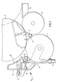
- Die Figuren 1 und 2 zeigen eine erfindungsgemäße Tragwalzen-Wickelmaschine, bei der die Ausstoßfläche des Ausstoßbalkens in Richtung zur Tragwalze schwenkbar ist.
Figur 3 zeigt eine Tragwalzen-Wickelmaschine mit einem Ausstoßbalken, dessen Ausstoßfläche mit einem Verlängerungsblech verlängerbar ist.
- Figures 1 and 2 show a support roller winding machine according to the invention, in which the ejection surface of the ejection bar can be pivoted in the direction of the support roller.
- FIG. 3 shows a support roller winding machine with an ejection bar, the ejection surface of which can be extended with an extension plate.
Die Tragwalzen-Wickelmaschine nach den Ausführungsbeispielen weist zwei Tragwalzen 1, 2 auf, zwischen denen ein Walzenbett 3 ausgebildet ist, in dem die Wickelrollen 4 während des Aufwickelns auf den Tragwalzen 1, 2 aufliegen. Die in Längsrichtung in Einzelbahnen aufgeteilte Materialbahn, vorzugsweise eine Papier- oder Kartonbahn, wird von unten - von der Tragwalze 1 umgelenkt - zwischen den Tragwalzen 1, 2 in das Tragwalzenbett 3 geführt und auf fluchtend aufgereihte Hülsen 5 gewickelt. Derartige Doppeltragwalzen- Wickelmaschinen sind bekannt, auf konstruktive Einzelheiten wird daher nicht eingegangen.The carrier roller winding machine according to the exemplary embodiments has two
An beiden Stirnseiten der Tragwalze 1 ist jeweils ein Hebel 6 koaxial zur Drehachse der Tragwalze 1 schwenkbar angelenkt. Die Schwenkbewegung wird mittels einer Verstelleinheit - im vorliegenden Beispiel einer angelenkten Kolben-Zylindereinheit 7 - durchgeführt. Die Kolben-Zylinder-Einheit 7 ist in beiden Schwenkrichtungen etwas nachgiebig ausgeführt, so daß die Hebel 6 in Grenzen elastisch angekoppelt sind. Die freien Ende der Hebel 6 sind in Richtung zum Walzenbett 3 abgewinkelt und tragen eine Rollenausstoß- und Hülseneinlegeeinrichtung 8, die im folgenden näher beschrieben wird.On both ends of the support roller 1, a
Am abgewinkelten Teil der Hebel 6 ist ein sich quer über die Arbeitsbreite erstreckender Ausstoßbalken 9 befestigt. In der Ausführungsform nach den Figuren 1 und 2 ist der Ausstoßbalken 9 an zusätzlichen, an den Hebeln 6 angelenkten Schwenkarmen 10 befestigt, die mittels einer Kolben-Zylindereinheit 11 relativ zu den Hebeln 6 in Richtung der Tragwalze 1 schwenkbar sind. In der Ausführungsform nach Figur 3 ist der Ausstoßbalken 9 fest mit den Hebeln 6 verbunden.On the angled part of the
Der Ausstoßbalken 9 dient zum Ausstoßen einer fertigen Wickelrolle 4 über die Tragwalze 2 auf eine Absenkbühne 12. Seine der Tragwalze 2 zugewandte Ausstoßfläche 13 ist in etwa dem Umfang einer Wickelrolle 4 angepaßt geformt und erstreckt sich in etwa radial zur Tragwalze 1. In vorgeschwenkter Position (in den Figuren 1-3 strichpunktiert gezeichnet) erstreckt sich die Ausstoßfläche 13 bis in die Nähe der Scheitellinie der Tragwalze 2.The
Weiterhin enthält die Rollenausstoß- und Hülseneinlegeeinrichtung 8 eine Spannzange 14 zum Einlegen neuer Hülsen 5 in das Walzenbett 3, deren Spannbacken sich im Bereich zwischen Ausstoßbalken 9 und Tragwalze 1 befinden. Die Spannzange 14 ist an dem abgewinkelten Teil der Hebel 6 befestigt. Der Aufbau derartiger Spannzangen ist bekannt und z.B. in der DE-OS 35 27 377 oder in der DE-PS 29 48 877 beschrieben.Furthermore, the roller ejection and sleeve insertion device 8 contains a
Bei der Ausführungsform nach den Figuren 1 und 2 ist die Ausstoßfläche 13 bis in den Bereich der Spannzange 14 soweit verlängert, daß bei vorgeschwenkter Position des Schwenkarms 10 (Figur 2) sie bis kurz vor die Tragwalze 1 reicht. Bei rückgeschwenkter Position der Schwenkarme 10 - dort decken sich die Schwenkarme 10 mit dem abgewinkelten Teil der Hebel 6 -, ist der Abstand zwischen dem unteren Ende der Ausstoßfläche 13 und der Tragwalze 1 so groß, daß die Hülsen 5 durch den Zwischenraum problemlos in das Walzenbett 3 eingelegt werden können.In the embodiment according to FIGS. 1 and 2, the
Bei der Ausführungsform nach Figur 3 ist an dem der Tragwalze 1 zugewandten Ende der Ausstoßfläche 13 ein maschinenbreites Verlängerungsblech 15 um eine zu den Tragwalzenachsen parallele Schwenkachse 16 angelenkt. Das Blech 15 kann soweit zurückgeschwenkt werden, daß es an der Ausstoßfläche 13 anliegt und so den erforderlichen Zwischenraum zur Tragwalze 1 zum Einlegen von Hülsen 5 freigibt. Andererseits kann das Blech 15 bis kurz vor die Tragwalze 1 heruntergeklappt werden, um die Ausstoßfläche 13 bis zur Tragwalze 1 zu verlängern.In the embodiment according to FIG. 3, a machine-
Anstelle des klappbaren Verlängerungsbleches 15 ist ebenso der Einsatz eines Parallel zur Ausstoßfläche 13 verschiebbaren Verlängerungsbleches möglich.Instead of the
Die vorstehend beschriebene Doppeltragwalzen-Wickelmaschine arbeitet wie folgt:The double carrier roll winding machine described above works as follows:
Im Normalbetrieb, wenn leere Hülsen 5 in das Walzenbett 5 eingelegt werden und volle Wickelrollen 4 ausgestoßen werden, ist der Schwenkarm 10 zurückgeschwenkt (Figur 1) bzw. das Verlängerungsblech 15 ist gegen die Ausstoßfläche 13 zurückgeklappt (Figur 3). Dadurch ist ausreichend Freiraum zwischen der Ausstoßfläche 13 und der Tragwalze 1, um eine störungsfreie Funktion der Spannzange 14 zu gewährleisten.In normal operation, when
Vor einem Rollenwechsel werden in der Wartestellung leere Hülsen 5 in die Spannzange 14 eingelegt und von dieser gehalten. Zum Rollenwechsel wird der Ausstoßbalken 9 in Richtung des Walzenbetts 3 geschwenkt und stößt dabei die volle Rolle 4 aus dem Walzenbett 3 auf die Absenkbühne 12. Beim Vorschwenken wird die Spannzange 14 mit den leeren Hülsen 5 gleichzeitig in Richtung Walzenbett 3 bewegt, wo die Zange 14 öffnet und die Hülsen 5 auf die Tragwalzen 1, 2 ablegt werden. Nach dem Rückschwenken der Ausstoß- und Einlegevorrichtung 8, sowie nach dem Befestigen der neuen Materialbahn an den Hülsen 5, werden die Tragwalzen 1, 2 zum Aufwickeln in eine Drehbewegung versetzt.Before a roll change,
Falls Rollen 17 mit einem so geringen Durchmesser aus dem Walzenbett 3 entfernt werden müssen, bei dem die Ausstoß- und Einlegeeinrichtung 8 in der vorhin beschriebenen Weise nicht mehr funktionsfähig ist, werden in der Warteposition die Schwenkarme (10) relativ zu den Hebeln 6 in Richtung des Walzenbetts 3 geschwenkt (Figur 2) bzw. das Verlängerungsblech 15 wird in Richtung zur Tragwalze 1 heruntergeklappt. So wird jeweils eine bis an die Tragwalze 1 reichende Fläche geschaffen. Anschließend werden die Hebel 6 mit der Kolben-Zylindereinheit 7 in Richtung des Walzenbetts 3 geschwenkt, bis die Ausstoßfäche 13 (Figur 2) bzw. das Verlängerungsblech 15 (Figur 3) an den Rollen 17 anliegt und diese gegen die Tragwalze 2 drückt. Die Tragwalze 2 wird nun im Uhrzeigersinn (Pfeil 18) angetrieben. Durch die Drehbewegung der Tragwalze 2 werden die Rollen 17 zwischen der Tragwalze 2 und der Ausstoßfläche 13 bzw. dem Verlängerungsblech 15 bis zur Scheitellinie der Tragwalze 2 hochgefördert, von wo sie selbsttätig auf die Absenkbühne 12 rollen. Über die Kolben-Zylinder-Einheit 7 ist die Rollenausstoßeinrichtung 8 und somit auch die Ausstoßfläche 13 in beiden Schwenkrichtungen nachgiebig ausgeführt, so daß der Kontakt zwischen der Tragwalze 2, den Rollen 17 und der Ausstoßfläche 13 ständig, mit annähernd gleichem Druck aufrechterhalten wird.If
Claims (10)
Priority Applications (1)
| Application Number | Priority Date | Filing Date | Title |
|---|---|---|---|
| AT89102730T ATE92000T1 (en) | 1988-04-09 | 1989-02-17 | METHOD AND DEVICE FOR WINDING MATERIAL WEBS, IN PARTICULAR PAPER WEBS OR CARDBOARD WEBS. |
Applications Claiming Priority (2)
| Application Number | Priority Date | Filing Date | Title |
|---|---|---|---|
| DE3811871A DE3811871A1 (en) | 1988-04-09 | 1988-04-09 | METHOD AND DEVICE FOR WINDING MATERIALS, IN PARTICULAR PAPER OR CARDBOARD |
| DE3811871 | 1988-04-09 |
Publications (3)
| Publication Number | Publication Date |
|---|---|
| EP0337079A2 true EP0337079A2 (en) | 1989-10-18 |
| EP0337079A3 EP0337079A3 (en) | 1990-08-16 |
| EP0337079B1 EP0337079B1 (en) | 1993-07-28 |
Family
ID=6351654
Family Applications (1)
| Application Number | Title | Priority Date | Filing Date |
|---|---|---|---|
| EP89102730A Expired - Lifetime EP0337079B1 (en) | 1988-04-09 | 1989-02-17 | Process and device for winding webs of material, particularly paper- or cardboard webs |
Country Status (7)
| Country | Link |
|---|---|
| US (1) | US4974786A (en) |
| EP (1) | EP0337079B1 (en) |
| JP (1) | JP2672365B2 (en) |
| AT (1) | ATE92000T1 (en) |
| DE (2) | DE3811871A1 (en) |
| ES (1) | ES2051901T3 (en) |
| FI (1) | FI94332C (en) |
Families Citing this family (6)
| Publication number | Priority date | Publication date | Assignee | Title |
|---|---|---|---|---|
| JP2546206Y2 (en) * | 1991-03-01 | 1997-08-27 | 三菱重工業株式会社 | Web take-up device |
| DE4334029C2 (en) * | 1993-10-06 | 1998-01-22 | Jagenberg Papiertech Gmbh | Carrier roll winding machine |
| DE19743070A1 (en) * | 1997-09-30 | 1999-04-01 | Jagenberg Papiertech Gmbh | Carrier roll winding machine |
| IT1313815B1 (en) * | 1999-11-03 | 2002-09-23 | Giovanni Gambini | INTRODUCTION DEVICE FOR A WINDING SOUL IN A REWINDER MACHINE |
| IT1398724B1 (en) * | 2010-03-16 | 2013-03-18 | Celli Paper S P A A | "MACHINE AND METHOD FOR WINDING COILS OF RIBBED MATERIAL" |
| US9187285B2 (en) * | 2012-11-19 | 2015-11-17 | Valmet Technologies, Inc. | Slitter-winder of a fiber production line |
Citations (5)
| Publication number | Priority date | Publication date | Assignee | Title |
|---|---|---|---|---|
| DE2948877A1 (en) * | 1979-12-05 | 1981-06-11 | Jagenberg-Werke AG, 4000 Düsseldorf | DEVICE FOR LOCALLY INSERTING WRAPPING SLEEVES IN WRAPPING MACHINES |
| DE3151256A1 (en) * | 1981-01-09 | 1982-10-28 | Jagenberg-Werke AG, 4000 Düsseldorf | Device on axleless winding machines |
| DE3527377A1 (en) * | 1985-07-31 | 1987-02-12 | Jagenberg Ag | METHOD AND DOUBLE CARRIER ROLLING MACHINE FOR AUTOMATICALLY PUTTING IN A WINDING SLEEVE SUITABLE FOR RECORDING A TRACK OF GOODS |
| GB2183610A (en) * | 1985-11-28 | 1987-06-10 | Waertsilae Oy Ab | Web winding method and winder |
| JPS641452A (en) * | 1987-06-24 | 1989-01-05 | Shokichi Kumakura | Generating magnetic load reducer of generator for bicycle in unlighted travelling |
Family Cites Families (6)
| Publication number | Priority date | Publication date | Assignee | Title |
|---|---|---|---|---|
| FI53560C (en) * | 1976-03-12 | 1978-06-12 | Ahlstroem Oy | FOERFARANDE OCH ANORDNING FOER UPPRULLNING AV MATERIALBANOR |
| AT373220B (en) * | 1979-07-27 | 1983-12-27 | Voith Gmbh J M | DOUBLE CARRIER ROLLER FOR REWINDING MATERIALS |
| FI63918C (en) * | 1980-10-21 | 1983-09-12 | Waertsilae Oy Ab | ANORDNING FOER RULLNING AV PAPPERSBANOR |
| AT376950B (en) * | 1981-12-24 | 1985-01-25 | Jagenberg Werke Ag | DEVICE ON AXLE WRAPPING MACHINES |
| CA1201055A (en) * | 1983-02-04 | 1986-02-25 | Louis J. Bagnato | Cut off knife |
| FI69820C (en) * | 1983-05-12 | 1986-05-26 | Waertsilae Oy Ab | ANORDNING FOER RULLNING AV MATERIALBANA |
-
1988
- 1988-04-09 DE DE3811871A patent/DE3811871A1/en not_active Withdrawn
-
1989
- 1989-02-17 AT AT89102730T patent/ATE92000T1/en not_active IP Right Cessation
- 1989-02-17 ES ES89102730T patent/ES2051901T3/en not_active Expired - Lifetime
- 1989-02-17 EP EP89102730A patent/EP0337079B1/en not_active Expired - Lifetime
- 1989-02-17 DE DE8989102730T patent/DE58905005D1/en not_active Expired - Fee Related
- 1989-04-06 US US07/334,648 patent/US4974786A/en not_active Expired - Lifetime
- 1989-04-07 FI FI891675A patent/FI94332C/en not_active IP Right Cessation
- 1989-04-10 JP JP1088202A patent/JP2672365B2/en not_active Expired - Fee Related
Patent Citations (5)
| Publication number | Priority date | Publication date | Assignee | Title |
|---|---|---|---|---|
| DE2948877A1 (en) * | 1979-12-05 | 1981-06-11 | Jagenberg-Werke AG, 4000 Düsseldorf | DEVICE FOR LOCALLY INSERTING WRAPPING SLEEVES IN WRAPPING MACHINES |
| DE3151256A1 (en) * | 1981-01-09 | 1982-10-28 | Jagenberg-Werke AG, 4000 Düsseldorf | Device on axleless winding machines |
| DE3527377A1 (en) * | 1985-07-31 | 1987-02-12 | Jagenberg Ag | METHOD AND DOUBLE CARRIER ROLLING MACHINE FOR AUTOMATICALLY PUTTING IN A WINDING SLEEVE SUITABLE FOR RECORDING A TRACK OF GOODS |
| GB2183610A (en) * | 1985-11-28 | 1987-06-10 | Waertsilae Oy Ab | Web winding method and winder |
| JPS641452A (en) * | 1987-06-24 | 1989-01-05 | Shokichi Kumakura | Generating magnetic load reducer of generator for bicycle in unlighted travelling |
Non-Patent Citations (1)
| Title |
|---|
| PATENT ABSTRACTS OF JAPAN, Band 7, Nr. 85 (M-206)[1230], 9. April 1983; & JP-A-1 001 452 (MITSUBISHI JUKOGYO K.K.) 22-01-1983 * |
Also Published As
| Publication number | Publication date |
|---|---|
| FI94332B (en) | 1995-05-15 |
| EP0337079B1 (en) | 1993-07-28 |
| EP0337079A3 (en) | 1990-08-16 |
| FI891675A (en) | 1989-10-10 |
| US4974786A (en) | 1990-12-04 |
| JPH01294143A (en) | 1989-11-28 |
| ES2051901T3 (en) | 1994-07-01 |
| DE58905005D1 (en) | 1993-09-02 |
| DE3811871A1 (en) | 1989-10-26 |
| FI94332C (en) | 1995-08-25 |
| JP2672365B2 (en) | 1997-11-05 |
| ATE92000T1 (en) | 1993-08-15 |
| FI891675A0 (en) | 1989-04-07 |
Similar Documents
| Publication | Publication Date | Title |
|---|---|---|
| EP0654349B2 (en) | Cassette for automatically exchanging printing plates in a printing machine | |
| EP0734859B1 (en) | Device for exchanging printing plates | |
| DE3347986C2 (en) | ||
| DE2948877C2 (en) | Double drum winding machine | |
| DE2930474C2 (en) | Double roller developing machine | |
| DE3108550C2 (en) | ||
| AT401922B (en) | WINDING MACHINE FOR SHAPED GOODS, IN PARTICULAR PAPER | |
| DE4334029C2 (en) | Carrier roll winding machine | |
| EP0656307A1 (en) | Cylinder for transporting signatures | |
| DE3040398C2 (en) | Process for exchanging a finished lap for an empty lap core in a double-roll winder and device for carrying out the process | |
| EP0337079B1 (en) | Process and device for winding webs of material, particularly paper- or cardboard webs | |
| AT393492B (en) | DOUBLE CARRIER ROLLING MACHINE FOR WRAPPING PRODUCT COVERS, IN PARTICULAR PAPER OR CARDBOARD FILES, ON DIFFERENT DIAMETERS | |
| DE2259485A1 (en) | DEVICE FOR CONNECTING MATERIAL TRAILS | |
| DE2649289B2 (en) | Roll changing device in a roll-up device for webs | |
| DE3527377C2 (en) | ||
| EP0406581B1 (en) | Arrangement for chopping of a web on a reversing winder | |
| EP1090754A1 (en) | Device for changing a cylindrical printing sleeve | |
| DE4415316C2 (en) | Roll winding machine | |
| DE1761518A1 (en) | Device for uninterrupted feeding of folded paper webs | |
| EP0161531B1 (en) | Transfer drum for sheet transportation | |
| EP0887297A2 (en) | Winding device for a material web, in particular for a roll cutting device | |
| DE3604915A1 (en) | Paper feed device for a printer | |
| EP0327725A1 (en) | Double support roller winding machine for winding a web of material, in particular a paper or cardboard web, onto core tubes | |
| EP0792813A1 (en) | Machine for unpacking rolls, especially printing paper rolls | |
| DE102017204913A1 (en) | Method for mounting a plate and a printing press for carrying out the method |
Legal Events
| Date | Code | Title | Description |
|---|---|---|---|
| PUAI | Public reference made under article 153(3) epc to a published international application that has entered the european phase |
Free format text: ORIGINAL CODE: 0009012 |
|
| AK | Designated contracting states |
Kind code of ref document: A2 Designated state(s): AT CH DE ES FR GB IT LI NL SE |
|
| PUAL | Search report despatched |
Free format text: ORIGINAL CODE: 0009013 |
|
| AK | Designated contracting states |
Kind code of ref document: A3 Designated state(s): AT CH DE ES FR GB IT LI NL SE |
|
| 17P | Request for examination filed |
Effective date: 19900714 |
|
| 17Q | First examination report despatched |
Effective date: 19920226 |
|
| GRAA | (expected) grant |
Free format text: ORIGINAL CODE: 0009210 |
|
| AK | Designated contracting states |
Kind code of ref document: B1 Designated state(s): AT CH DE ES FR GB IT LI NL SE |
|
| PG25 | Lapsed in a contracting state [announced via postgrant information from national office to epo] |
Ref country code: SE Effective date: 19930728 Ref country code: NL Effective date: 19930728 |
|
| REF | Corresponds to: |
Ref document number: 92000 Country of ref document: AT Date of ref document: 19930815 Kind code of ref document: T |
|
| ITF | It: translation for a ep patent filed |
Owner name: DE DOMINICIS & MAYER S.R.L. |
|
| GBT | Gb: translation of ep patent filed (gb section 77(6)(a)/1977) |
Effective date: 19930729 |
|
| REF | Corresponds to: |
Ref document number: 58905005 Country of ref document: DE Date of ref document: 19930902 |
|
| ET | Fr: translation filed | ||
| NLV1 | Nl: lapsed or annulled due to failure to fulfill the requirements of art. 29p and 29m of the patents act | ||
| PG25 | Lapsed in a contracting state [announced via postgrant information from national office to epo] |
Ref country code: LI Effective date: 19940228 Ref country code: CH Effective date: 19940228 |
|
| PLBE | No opposition filed within time limit |
Free format text: ORIGINAL CODE: 0009261 |
|
| STAA | Information on the status of an ep patent application or granted ep patent |
Free format text: STATUS: NO OPPOSITION FILED WITHIN TIME LIMIT |
|
| REG | Reference to a national code |
Ref country code: ES Ref legal event code: FG2A Ref document number: 2051901 Country of ref document: ES Kind code of ref document: T3 |
|
| 26N | No opposition filed | ||
| PG25 | Lapsed in a contracting state [announced via postgrant information from national office to epo] |
Ref country code: FR Effective date: 19941031 |
|
| REG | Reference to a national code |
Ref country code: CH Ref legal event code: PL |
|
| REG | Reference to a national code |
Ref country code: FR Ref legal event code: ST |
|
| REG | Reference to a national code |
Ref country code: GB Ref legal event code: IF02 |
|
| PGFP | Annual fee paid to national office [announced via postgrant information from national office to epo] |
Ref country code: GB Payment date: 20030124 Year of fee payment: 15 |
|
| PGFP | Annual fee paid to national office [announced via postgrant information from national office to epo] |
Ref country code: AT Payment date: 20030221 Year of fee payment: 15 |
|
| PG25 | Lapsed in a contracting state [announced via postgrant information from national office to epo] |
Ref country code: GB Free format text: LAPSE BECAUSE OF NON-PAYMENT OF DUE FEES Effective date: 20040217 Ref country code: AT Free format text: LAPSE BECAUSE OF NON-PAYMENT OF DUE FEES Effective date: 20040217 |
|
| GBPC | Gb: european patent ceased through non-payment of renewal fee |
Effective date: 20040217 |
|
| PGFP | Annual fee paid to national office [announced via postgrant information from national office to epo] |
Ref country code: DE Payment date: 20060214 Year of fee payment: 18 |
|
| PGFP | Annual fee paid to national office [announced via postgrant information from national office to epo] |
Ref country code: ES Payment date: 20060227 Year of fee payment: 18 |
|
| PGFP | Annual fee paid to national office [announced via postgrant information from national office to epo] |
Ref country code: IT Payment date: 20060228 Year of fee payment: 18 |
|
| PG25 | Lapsed in a contracting state [announced via postgrant information from national office to epo] |
Ref country code: DE Free format text: LAPSE BECAUSE OF NON-PAYMENT OF DUE FEES Effective date: 20070901 |
|
| REG | Reference to a national code |
Ref country code: ES Ref legal event code: FD2A Effective date: 20070219 |
|
| PG25 | Lapsed in a contracting state [announced via postgrant information from national office to epo] |
Ref country code: ES Free format text: LAPSE BECAUSE OF NON-PAYMENT OF DUE FEES Effective date: 20070219 |
|
| PG25 | Lapsed in a contracting state [announced via postgrant information from national office to epo] |
Ref country code: IT Free format text: LAPSE BECAUSE OF NON-PAYMENT OF DUE FEES Effective date: 20070217 |