EP0336776B1 - Bildvergrösserung - Google Patents
Bildvergrösserung Download PDFInfo
- Publication number
- EP0336776B1 EP0336776B1 EP89303461A EP89303461A EP0336776B1 EP 0336776 B1 EP0336776 B1 EP 0336776B1 EP 89303461 A EP89303461 A EP 89303461A EP 89303461 A EP89303461 A EP 89303461A EP 0336776 B1 EP0336776 B1 EP 0336776B1
- Authority
- EP
- European Patent Office
- Prior art keywords
- array
- sub
- unit area
- mode
- corresponding unit
- Prior art date
- Legal status (The legal status is an assumption and is not a legal conclusion. Google has not performed a legal analysis and makes no representation as to the accuracy of the status listed.)
- Expired - Lifetime
Links
Images


Classifications
-
- G—PHYSICS
- G06—COMPUTING OR CALCULATING; COUNTING
- G06T—IMAGE DATA PROCESSING OR GENERATION, IN GENERAL
- G06T3/00—Geometric image transformations in the plane of the image
- G06T3/40—Scaling of whole images or parts thereof, e.g. expanding or contracting
- G06T3/4007—Scaling of whole images or parts thereof, e.g. expanding or contracting based on interpolation, e.g. bilinear interpolation
-
- H—ELECTRICITY
- H04—ELECTRIC COMMUNICATION TECHNIQUE
- H04N—PICTORIAL COMMUNICATION, e.g. TELEVISION
- H04N1/00—Scanning, transmission or reproduction of documents or the like, e.g. facsimile transmission; Details thereof
- H04N1/387—Composing, repositioning or otherwise geometrically modifying originals
- H04N1/393—Enlarging or reducing
- H04N1/3935—Enlarging or reducing with modification of image resolution, i.e. determining the values of picture elements at new relative positions
-
- H—ELECTRICITY
- H04—ELECTRIC COMMUNICATION TECHNIQUE
- H04N—PICTORIAL COMMUNICATION, e.g. TELEVISION
- H04N1/00—Scanning, transmission or reproduction of documents or the like, e.g. facsimile transmission; Details thereof
- H04N1/40—Picture signal circuits
- H04N1/40068—Modification of image resolution, i.e. determining the values of picture elements at new relative positions
Definitions
- the present invention relates to image magnification, for example image magnification of the type in which the magnified image is formed by determining values of new pixels which are to be interpolated between original pixel centers constituting an original image.
- a process and apparatus for such image magnification is applicable both to a simple image magnification with a constant pixel density carried out in image display and image printing, and to an increase in pixel density, for example, in the conversion from a Group 3 (G3) type to a Group 4 (G4) type in facsimile transmission systems.
- G3 Group 3
- G4 Group 4
- One example of an image conversion process suitable for magnifying an image is a high speed projection method as proposed in Japanese Unexamined Patent Publication A58-97958 and the Journal of the Institute of Image Electronics Engineers of Japan vol. 11, NO. 2, 1982, pp 72 ⁇ pp 83.
- Such an image conversion process employs a first set of pixel values representing an original image to be converted, which pixel values relate respectively to the points of a first two-dimensional array of points on the original image, to derive a second set of pixel values representing a converted version of the original image, which pixel values are greater in number than the pixel values of the first set and relate respectively to the points of a second two-dimensional array of points on the converted version of the original image.
- the process may be considered to comprise the following steps for each pixel value in turn of the said second set, the said second array being considered as projected onto the first array so that the projected second array occupies the same area as the first array and so that rows and columns of the projected second array are parallel respectively to rows and columns of the first array:
- Such a process employing the high speed projection method can provide high speed processing in the determination of the concentration (pixel values) of the converted pixels by carrying out logic calculations instead of arithmetic calculations during the image conversion (magnification) process.
- Figure 1 shows an example of a process according to such a high speed projection method in which, as a first step, a unit area of the first array, surrounded by four adjacent original pixel centers (first-array points) A to D, is divided into four regions corresponding respectively to the four adjacent original pixel centers, in such a way that all points in a particular region are nearer to the associated one of the four adjacent original pixel centers than they are to the other three centers.
- the area of a converted pixel of the magnified image whose pixel center (second-array point) lies within the unit area of the original image when the magnified image is considered as projected onto the original image, is projected onto that unit area, as shown in Fig. 1.
- magnification factors in the lateral (horizontal) direction and in the longitudinal (vertical) direction are p and q respectively
- the length of a lateral side of the area of the converted pixel is 1/p of the length of a lateral side of the area of an original pixel
- the length of a longitudinal side of the area of the converted pixel is 1/q of the length of a longitudinal side of the area of the original pixel.
- the concentrations (first-set pixel values) of the above four adjacent first-array pixels are denoted by I A , I B , I C , and I D , respectively, and the respective proportions of the area of the converted pixel projected onto the above sections are denoted by W A , W B , W C , and W D
- the calculated value I R is quantized to a binary value, I.e., I R is set to one (black) when the calculated I R value is greater than or equal to 0.5, and I R is set to zero (white) when the calculated I R value is smaller than 0.5.
- the above calculated value of the concentration I R is made equal to the concentration value of that (nearest) original pixel regardless of the concentrations of the other three original pixels.
- the boundary for defining such a range is generally given as a hyperbolic curve for each of the original pixels. However, as the magnification rate becomes large, the boundary comes close to the center of the unit area, i.e., the boundaries for the four original pixels come close to the lines which divide the unit area into the above four regions, i.e, the x and y axes in Figure 1.
- a smooth oblique line in an original image becomes a step-like, angular shape when magnified by a large magnification factor.
- a hyperbolic boundary additionally causes computational complexity.
- the high speed projection method as mentioned above is only effective for providing smoothness in magnified oblique lines at the angle of 45 degrees. Magnified oblique lines at angles other than 45 degrees exhibit distortion.
- Figures 3A, 3B, and 3C show the results of the magnification of an oblique line in an original image by the above-mentioned high speed projection method, wherein the angle of the oblique line is 45 degrees in Fig. 3A, an intermediate angle between 45 degrees and 90 degrees in Fig. 3B, and an intermediate angle between 0 degrees and 45 degrees in Fig. 3C.
- a satisfactorily smooth magnification is not assured for oblique lines at an angle other than 45 degree.
- the magnification factor becomes large, the step-like shape becomes prominent.
- An image conversion process embodying the present invention is characterised by the step of determining, between steps (a) and (b), whether the first-set pixel values relating to a group of first-array points in the vicinity of the calculated location match any one of a plurality of predetermined image patterns that are consistent with original image line portions extending at a predetermined angle to a predetermined reference direction of the first array, and, if such a match is found, the mode of sub-division used to define the said predetermined plurality of different sections for the purposes of step (b) is selected from a predetermined set of different possible modes of sub-division, so that a dividing line employed in the selected mode and separating the section containing the calculated location from an adjacent section of the said corresponding unit area extends at substantially the said predetermined angle to the said predetermined reference direction.
- image conversion apparatus for employing a first set of pixel values representing an original image to be converted, which pixel values relate respectively to the points of a first two-dimensional array of points on the original image, to derive a second set of pixel values representing a converted version of the original image, which pixel values are greater in number than the pixel values of the first set and relate respectively to the points of a second two-dimensional array of points on the converted version of the original image;
- the angle of an original line image (original image line portion) in a predetermined vicinity of the unit area is determined by comparing values of a group of original pixels in that predetermined vicinity of the unit area with a set of predetermined image patterns.
- Figure 4 shows the original pixel centers used in a step for comparing values of such a group of the original pixels in that predetermined vicinity of the unit area with each pattern in the set of predetermined patterns.
- the area surrounded by the four original pixel centers A, B, C, and D is a unit area wherein new (converted) pixels are to be interpolated, and the other twelve original pixel centers denoted by M, L, K, P , E, J, F, I, N, G, H, and O, together with the above A, B, C, and D, are included in a sub-array in the above predetermined vicinity of the unit area, i.e. in the pattern matching step of the process, the group members are selected from amongst the sub-array of these sixteen original pixels, and the pixel values of the group members are compared with each of the predetermined patterns.
- the patterns are sorted into eight types denoted by P1, P2, P3, P4, P5, P6, P7, and P8, according to the combination of the original pixel centers as shown in Fig. 5.
- Nos. 4 and 8 each correspond to a pattern showing a right-angled corner.
- a selection of one of a plurality of predetermined modes of division of the unit area is made according to the line image detected in the pattern matching step, the predetermined modes of division of the plurality having been provided in advance corresponding to the predetermined patterns, so that each of the new pixels in a section which is generated by one of the modes of division, has the same value determined by values of the original pixels in the predetermined vicinity.
- the predetermined modes of division of the unit area are shown in Figures 6, 7A, 7B, 7C, 7D, 7E, 8A, 8B, 8C, 8D, and 8E.
- the mode of division shown in Fig. 6 corresponds to the patterns of Nos. 1, 4, 5, and 8 in the types P1 to P4 in Fig. 5.
- This mode of division is identical to the division shown in the conventional division of the unit area as shown in Fig. 2. (The previously-proposed high speed projection method provides only this one mode of division).
- Fig. 7A The mode of division shown in Fig. 7A corresponds to Nos. 2 and 6 in the types P1 to P4.
- Fig. 7B The mode of division shown in Fig. 7B corresponds to Nos. 1 and 2 in the type P5.
- Fig. 7C The mode of division shown in Fig. 7C corresponds to Nos. 1 and 2 in the type P6.
- Fig. 7D The mode of division shown in Fig. 7D corresponds to Nos. 3 and 4 in the type P6.
- Fig. 7E The mode of division shown in Fig. 7E corresponds to Nos. 3 and 4 in the type P5.
- Fig. 8A The mode of division shown in Fig. 8A corresponds to Nos. 3 and 7 in the types P1 to P4 in Fig. 5.
- Fig. 8B The mode of division shown in Fig. 8B corresponds to Nos. 1 and 2 in the type P7.
- Fig. 8C The mode of division shown in Fig. 8C corresponds to Nos. 3 and 4 in the type P7.
- Fig. 8D The mode of division shown in Fig. 8D corresponds to Nos. 3 and 4 in the type P8.
- Fig. 8E The mode of division shown in Fig. 8E corresponds to Nos. 1 and 2 in the type P8.
- Figure 9 shows the value assigned for the pixels the center of which are in each section generated by the above dividing operation shown in Figs. 6, 7A, 7B, 7C, 7D, 7E, 8A, 8B, 8C, 8D, and 8E.
- the sections are denoted by the common references G1, G2, ... G8, G9, G10, G11, G12, G9′ , G10′ , G11′ , and G12′ in Figs. 6, 7A, 7B, 7C, 7D, 7E, 8A, 8B, 8C, 8D, 8E and 9.
- A, B, C, ... and I L denote the respective values of the pixels shown in Fig. 4, and + denotes a logical OR, * denotes a logical AND, and A ⁇ denotes a logical inversion of the value of the pixel A.
- values of new (converted) pixels in any of the sections G1, G2, G3, or G4 are each made equal to the value of the original pixel the center of which is at the corner concerned.
- G5 is black: when both A and 8 are black; when both A and C are black; or when both A and D are black (corresponding to A ⁇ (B+C+D)).
- G5 is black if A is black and B, C, D, F, and K are all white (corresponding to A ⁇ (B+C+D+ F ⁇ ⁇ K ⁇ ), and showing a right-angled corner by a white line image).
- G5 is white when A is white and B, C, D, F, and K are all black (corresponding to B ⁇ C ⁇ D ⁇ ( F ⁇ + K ⁇ ), and showing a right-angled corner by a black line image).
- Figure 10 shows an example of the operation of a first embodiment of the present invention.
- the black and white circles positioned in a square-latticed arrangement are each the original pixel centers constituting an original image
- a black circle indicates that the concentration value of the pixel is black
- a white circle indicates that the concentration value of the pixel is white.
- the magnification factor in both the horizontal and the vertical directions is three, and the small points shown arranged at three times the density of the original pixels show the positions on the original image that are to correspond respectively with the pixel centers of the magnified image.
- the unit area is the area surrounded by the four original pixels 1, 2, 5, and 6, because the pixel is contained in that area, i.e., the pixels 1, 2, 5, and 6, are selected as the aforementioned pixels A, B, C, and D in the present invention.
- the mode of division shown in Fig. 8A is selected in the mode selection step of the process and then it is determined that the coordinate of the converted pixel ⁇ is in the section G2, a convention that, when the coordinate of a converted pixel is on a line which divides a unit area, the converted pixel is assigned to the lower side of the sections divided by the line (hereinafter called lower side convention),being applied in this embodiment.
- the value of the converted pixel ⁇ is equal to the value of the original pixel B.
- B is black
- the value of the converted pixel ⁇ is black.
- the unit area is the area surrounded by the four original pixels 2, 3, 4, and 5, because the pixel is contained in that area, i.e., the pixels 2, 3, 4, and 5, are selected as the aforementioned pixels A, B, C, and D in the present invention.
- the mode of division shown in Fig. 8A is selected in the mode selection step of the process and then it is determined that the coordinate of the converted pixel ⁇ is in the section G8 using the lower side convention used before.
- the value of the converted pixel ⁇ is calculated as D ⁇ (A+B+C+ I ⁇ ⁇ L ⁇ ) +A ⁇ B ⁇ C ⁇ ( I ⁇ + L ⁇ ).
- A, B, and C are black, and L is white, the value of the converted pixel ⁇ is black.
- the unit area is the area surrounded by the four original pixels 5, 4, 7, and 8, because the pixel is contained in that area, i.e., the pixels 5, 4, 7, and 8, are selected as the aforementioned pixels A, B, C, and D in the present invention.
- the mode of division shown in Fig. 8B is then selected in the mode selection step of the process, and then it is determined that the coordinate of the converted pixel ⁇ is in the section G2.
- the value of the converted pixel ⁇ is equal to the value of the original pixel B, i.e., the value of the converted pixel ⁇ is black.
- a thick line shows a boundary of the area where the converted pixels are black.
- a converted (magnified) line image at the angle tan -1 1/2 which is smoother than the magnified line image by the conventional high speed projection method, is obtained by the first embodiment of the present invention.
- Figures 11A, 11B, and 11C show examples of the result of the magnification by the process for image magnification according to an embodiment of the present invention.
- Figure 11A shows a magnification result of an oblique line image at the angle of 45 degrees.
- magnification factors in the horizontal and lateral directions are both three.
- Figures 12A, 12B, 12C, 12D, and 12E show the mode of division corresponding to line images (original image line portions) at the angle ⁇ (tan -1 1 ⁇ ⁇ ⁇ tan -1 2)
- Figures 13A, 13B, 13C, 13D, and 13E show the mode of division corresponding to line images at the angle ⁇ (tan -1 1/2 ⁇ ⁇ ⁇ tan -1 1).
- the line which divides the unit area determines the distribution of the values of the converted pixels, if the angle of the dividing line is much different from the angle of the original line image, unevenness having a cycle corresponding to the size of the original unit area, i.e., the original pixel density, necessarily appears in the magnified line image.
- information relating to the angle of a line image is derived from the values of a combination of the original pixels in the predetermined vicinity of the unit area by comparing those values with a plurality of predetermined patterns. This is possible because the patterns are predetermined so as to correspond to portions of arrangements of pixel values each of which arrangements constitutes a line image having a definite angle.
- a corresponding one of the predetermined modes of division is selected.
- the "corresponding" means that in that mode of division, the angle of a line which divides the unit area conforms to the detected angle of the original line image in the vicinity of the unit area.
- the unevenness due to the difference of the angles between the line which determines the distribution of the values of the converted pixels, and the angle of the original line image can be reduced, ie. the quality of the magnified line image can be greatly improved in terms of smoothness of oblique line images, by the process according to this embodiment of the present invention.
- the process for image magnification according to the second embodiment further comprises the following two additional steps, preceding the aforementioned pattern matching step of the present invention.
- Figure 14 shows the additional steps which are carried out before the aforementioned pattern matching step in the second embodiment of the present invention.
- the patterns, and the combination of original pixels, the values of which are compared with the patterns are predetermined for each of the sub-areas, and the modes of division are defined within each of the sub-areas, as explained in the following.
- Figure 15 shows the combinations (sub-arrays) and the patterns which are predetermined for each of the sub-areas R1, R2, R3, and R4.
- the combination (sub-array) predetermined for each of the original pixel centers A, B, C, and D, respectively includes 3 ⁇ 3 original pixels arranged in a square lattice form having the corresponding corner of the unit area (the corresponding original pixel center) in its center.
- the type P1 for the sub-area R1 in Fig. 15 is the same as the patterns in the type P1 in Fig. 5 in the first embodiment of the present invention as a total (though the numberings are different in the two embodiments).
- the type P1 for the sub-area R2 in Fig. 15 is the same as the patterns in the type P2 in Fig. 5 as a total (though the numberings are different in the two embodiments).
- the type P1 for the sub-area R3 in Fig. 15 is the same as the patterns in the type P3 in Fig. 5 as a total (though the numberings are different in the two embodiments).
- the type P1 for the sub-area R4 in Fig. 15 is the same as the patterns in the type P4 in Fig. 5 as a total (though the numberings are different in the two embodiments).
- the type P2 for the sub-area R1 in Fig. 15 is the same as the patterns Nos. 1 and 2 in the type P5 in Fig. 5.
- the type P2 for the sub-area R2 in Fig. 15 is the same as the patterns Nos. 1 and 2 in the type P6 in Fig. 5.
- the type P2 for the sub-area R3 in Fig. 15 is the same as the patterns Nos. 3 and 4 in the type P6 in Fig. 5.
- the type P2 for the sub-area R4 in Fig. 15 is the same as the patterns Nos. 3 and 4 in the type P5 in Fig. 5.
- the type P3 for the sub-area R1 in Fig. 15 is the same as the patterns Nos. 1 and 2 in the type P7 in Fig. 5.
- the type P3 for the sub-area R2 in Fig. 15 is the same as the patterns Nos. 3 and 4 in the type P7 in Fig. 5.
- the type P3 for the sub-area R3 in Fig. 15 is the same as the patterns Nos. 3 and 4 in the type P8 in Fig. 5.
- the type P3 for the sub-area R4 in Fig. 15 is the same as the patterns Nos. 1 and 2 in the type P8 in Fig. 5.
- comparison of the aforementioned combination of the original pixel values with all patterns of the types P1 to P8 is equivalent to the comparison of the combination for each of the sub-areas R1, R2, R3, and R4 with the corresponding patterns of the types P1 to P3 after the determination of the sub-area.
- the number of the operations of comparison is reduced in the second embodiment of the present invention.
- Figures 16A and 16B show the modes of division in the second embodiment of the present invention.
- the modes of division defined within each sub-area shown in Fig. 16 are each a part of one of the divisions shown in the first embodiment (Fig. 6, 7A, 7B, 7C, 7D, 7E, 8A, 8B, 8B, 8C, 8D, and 8E), and the denotations of the sections G1, G2, G3, G4, G5, G6,G7, G8, G9, G10, G11, and G12, are the same as in Fig. 6, 7A, 7B, 7C, 7D, 7E, 8A, 8B, 8B, 8C, 8D, and 8E.
- the mode of division M1 is selected for that section; when the patterns No. 3 or 4 in the type P1 are detected for each section, the mode of division M2 is selected for that section; when the patterns No. 5 or 6 in the type P1 are detected for each section, the mode of division M5 is selected for that section; when the patterns No. 7 or 8 in the type P1 are detected for each section, the mode of division M6 is selected for that section; when the patterns in the type P2 are detected for each section, the mode of division M3 is selected for that section; and when the patterns in the type P3 are detected for each section, the mode of division M4 is selected for that section.
- an unique mode M2 for the right-angled corners only is assigned, i.e., when one of the patterns Nos. 3 and 4 in the type P1 in each sub-area is detected.
- Figure 17 shows the logical expressions for obtaining values of the new pixels the center of which exists in each of the sections.
- the modes of division including a provision of the mode M2 for the line images showing a right-angled corner
- the logical expressions for obtaining values of the new pixels in each of the sections G5, G6, G7, and G8, are simplified as shown in Figure 17.
- the third embodiment of the present invention is provided for obtaining a further sharpness in the magnified line image, particularly, where the angle of the line image changes.
- Figure 18 shows the arrangement of original pixel centers in the vicinity of the third embodiment of the present invention.
- eight further original pixels Q, R, S, T, U, V, W, and X are added into the vicinity.
- These additional original pixels are added outside of the aforementioned 4 ⁇ 4 square lattice (sub-array), and two of the eight original pixels are abutting on each of the four original pixels which are at the corners of the 4 ⁇ 4 square lattice, in the vertical direction and in the horizontal direction, as shown in Fig. 18.
- the patterns and the combination of original pixels from which the group members whose pixel values will be compared with the patterns are selected are predetermined for each of the sub-areas, and the modes of division are defined within each of the sub-areas.
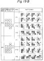
- Figures 19A and 19B show the combinations and the patterns which are predetermined for each of the sub-areas R1, R2, R3, and R4.
- the combination predetermined for the original pixel center A includes 3 ⁇ 3 original pixels arranged in a square lattice form having the corresponding corner A of the unit area (the corresponding original pixel center) in its center, and two additional original pixels Q and X in the far side from the unit area ABCD.
- the combination predetermined for the original pixel center B includes 3 ⁇ 3 original pixels arranged in a square lattice form having the corrersponding corner B of the unit area (the corresponding original pixel center) in its center, and two additional original pixels R and S in the far side from the unit area ABCD.
- the combination predetermined for the original pixel center C includes 3 ⁇ 3 original pixels arranged in a square lattice form having the corresponding corner C (the corresponding original pixel center) in its center, and two additional original pixels T and U in the far side from the unit area ABCD.
- the combination predetermined for the original pixel center D includes 3 ⁇ 3 original pixels arranged in a square lattice form having the corresponding corner D (the corresponding original pixel center) in its center, and two additional original pixels V and W in the far side from the unit area ABCD.
- the type P1 for each of the sub-areas R1, R2, R3, and R4 shown in Figs. 19A and 19B is the same as the corresponding patterns in the type P1 in Fig. 15 in the second embodiment of the present invention.
- the patterns of the types of P2 and P3 provides the characteristic features of the third embodiment of the present invention.
- the patterns Nos. 1 and 2 in the type P2 for each of the sub-areas R1, R2, R3, and R4, correspond to the line images at the angles ⁇ tan -1 2 without a change of the angle
- the patterns Nos. 3 and 4 in the type P2 for each of the sub-areas R1, R2, R3, and R4, correspond to the line images which are changing in slope between ⁇ tan -1 1 (45 degrees) and ⁇ tan -1 2, or between ⁇ tan -1 1 (45 degrees) and 90 degrees.
- the patterns Nos. 1 and 2 in the type P3 for each of the sub-areas R1, R2, R3, and R4, correspond to the line images at the angles ⁇ tan -1 1/2 without a change of the angle
- the patterns Nos. 3 and 4 in the type P3 for each of the sub-areas R1, R2, R3, and R4, correspond to the line images which are changing their slope between ⁇ tan -1 1 (45 degrees) and ⁇ tan -1 2, or between ⁇ tan -1 1 (45 degrees) and 0 degrees.
- the mode M1 corresponding to the angle ⁇ 45 degrees is selected for each of the sub-areas R1, R2, R3, and R4, to show a sharp angle change in the magnified image.
- the reason of the selection is as follows.
- the pattern No. 3 in the type P2 is detected. Then, if it is deemed that the detection of the pattern No. 3 in the type P2 shows a line image which is changing its slope between ⁇ tan -1 1 (45 degrees) and ⁇ tan -1 2, and the mode of division corresponding to the angles ⁇ tan -1 2 is selected, the magnification result at the angle changing portion is the same as the above result by the second embodiment of the present invention, i.e., no effect appears by the addition of the eight original pixels in the third embodiment of the present invention.
- the third embodiment of the present invention is effective only when the mode M1 corresponding to the angle ⁇ 45 degrees is selected for the detection of one of the patterns Nos. 3 and 4 in the types P2 and P3, for each of the sub-areas R1, R2, R3, and R4. According to this selection, an image of a sharp angle change between 90 degrees to 45 degrees or between 0 degrees to 45 degrees is maintained even after the magnification.
- Figures 20A and 20B show two examples of the magnification of the above sharp angle changes between 90 degrees to 45 degrees and between 0 degrees to 45 degrees, and Figure 21 shows a detail of the magnification process of the image shown in Fig. 20B.
- Figure 22 shows a block diagram of an embodiment of the apparatus for image magnification according to the present invention, and the construction of Fig. 22 carries out the process of the aforementioned second embodiment.
- reference numeral 1 denotes an x-coordinate calculating portion
- 2 denotes an original pixel data input portion
- 3 denotes a control portion
- 4 denotes a pattern detecting portion
- 5 denotes a section detecting portion
- 6 denotes a converted pixel value calculating portion.
- the x-coordinate calculating portion 1 receives an inverse 1/p of the magnification rate p in x direction and the initial x-coordinate of the converted pixel, calculates the x-coordinate of each converted pixel by adding the inverse 1/p to the x-coordinate of the preceding converted pixel, and then outputs the x-coordinate of the new converted pixel.
- the interval between two adjacent original pixels in both the x direction and the y direction are each supposed to be one, i.e., the size of the aforementioned unit area is one.
- the integer portion of the x-coordinate output is applied to the original pixel data input portion 2 as a carry signal.
- the decimal portion of the above x-coordinate output is applied to the section detecting portion 5, and the most significant bit of the decimal portion of the above x-coordinate output is applied to the pattern detecting portion 4.
- the most significant bit of the decimal portion of the above x-coordinate output includes information on the sub-areas (quadrants) where the center of the converted pixel exists, i.e., that most significant bit indicates whether the center of the converted pixel exists in R1, R2 side or R3, R4 side in the unit area shown in Fig. 14.
- the original pixel data input portion 2 receives three lines of the original pixel data for a predetermined interval. Each line corresponds to a row of the original pixels in the same y-coordinate, and the three adjacent lines are input into the original pixel data input portion 2 at the same time.
- These three lines correspond to the three lines in the aforementioned 3 ⁇ 3 square lattice form of the combination of the original pixels as shown in Fig. 15, and the original pixel data input portion 2 prepares a set of four bits data consisting of four original pixels adjacent each other in x direction for each of the three lines.
- the four original pixels in the three lines correspond to the four original pixels in three adjacent lines in the four lines (M, L, K, P), (E, A, D, J), (F, B, C, I), and (N, G, H, O), in 4 ⁇ 4 square lattice form shown in Fig. 14.
- the output (prepared data) of the original pixel data input portion 2 in each of the above three lines is shifted by one bit in x direction when the abovementioned carry signal is applied to the original pixel data input portion 2, and the output of the original pixel data input portion 2 is applied to both the pattern detecting portion 4 and the converted pixel value calculating portion 6.
- the pattern detecting portion 4 holds a plurality of predetermined patterns of the pixel data arrangement as shown in Fig. 15, and receives information on the sub-areas (quadrants) where the center of the converted pixel exists, i.e., information showing whether the center of the converted pixel exists in the R1, R2 side or the R3, R4 side in the unit area shown in Fig. 14, from the x-coordinate calculating portion 1, and information showing whether the center of the converted pixel exists in the R2, R3 side or the R1, R4 side, from the control portion 3, and the set of four hit data for each of the three lines from the original pixel data input portion 2.
- the pattern detecting portion 4 detects a pattern which is equal to the pattern consisting of the values of the aforementioned combination of the original pixels, among the above predetermined patterns, by comparing the pattern consisting of the values of the combination with each of the aforementioned predetermined patterns.
- the section detecting portion 5 holds a set of the x-coordinates of the dividing lines at the y-coordinite of converted pixels.
- the dividing lines include lines for all modes of division, and each of which lines devides a unit area (sub-area) into sections according to the corresponding mode of division as shown in Fig. 16A and 16B.
- the mode of division is selected according to the pattern which is detected in the pattern detecting portion.
- the section detecting portion 5 compares the x-coordinate of each converted pixel with the x-coordinates of the dividing lines for the selected mode mentioned above, and detects whether or not the x-coordinate of each converted pixel is larger than the x-coordinates of the dividing lines for the selected mode.
- the section detecting portion 5 can show the section where the coordinate of the converted pixel exists, when which mode is selected is known.
- the converted pixel value calculating portion 6 receives the above output of the section detecting portion 5, the pattern which is detected in the pattern detecting portion 4, the information on the sub-areas where the center of the converted pixel exists, and the set of original pixel data which is output from the original pixel data input portion 2, and then carries out the logical calculation as shown in Fig. 17 to obtain the value for the converted pixel.
- the control portion 3 controls all operation of the construction of Fig. 22, including supplying of the initial x-coordinate, (the inverse of) the magnification rate p, and the information on whether the center of the converted pixel exists in the R2, R3 side or the R1, R4 side in a unit area.
- Figure 23A shows an example of the construction of the x-coordinate calculating portion 1 and the original pixel data input portion 2 in Fig. 22.
- the construction shown in the dashed line 2 in Fig. 23A corresponds to the original pixel data input portion in Fig. 22, and is constructed by registers 201, 202, 203, 204, 205, 206, 207, 209, 210, 211, 213, 214, 215, and 216, and pixel select circuits 208, 212, and 217.
- the construction shown in the dashed line 1 in Fig. 23A corresponds to the x-coordinate calculating portion in Fig. 22, and is constructed by a multiplexer 11, registers 12, 14, 15, and 16, and an adder 13.
- the initial x-coordinate of the converted pixel is applied to one of the input terminal of the multiplexer 11, and then that input is selected, and therefore, the initial x-coordinate of the converted pixel is input into the register 12.
- the inverse 1/p of the magnification rate (in x direction) p is input into the register 16 as a pitch of the x-coordinate of the converted pixel.
- Each of three adjacent lines of the original pixel data is supplied to the corresponding one of the pixel select circuits 208, 212, and 217.
- the registers 205, 206, and 207 supplies the original pixel data in the first line to the pixel select circuits 208, the registers 209, 210, and 211 supplies the original pixel data in the second line to the pixel select circuits 212, and the registers 214, 215, and 216 supplies the original pixel data in the third line to the pixel select circuits 217.
- Each of the registers 205, 209, 214 holds sixteen bits of the original pixel data until the operation of the corresponding one of the pixel select circuits 208, 212, and 217 using the sixteen bits of the original pixel data is completed.
- each of the registers 206, 210, and 215 holds a last one bit of the preceding sixteen bits of the original pixel data, which preceding sixteen bits were held in the corresponding one of the registers 205, 209, and 214 for the preceding cycle of operation
- each of the registers 207, 211, and 216 holds two bits from the top of the next sixteen bits of the original pixel data, which next sixteen bits is to be held in the corresponding one of the registers 205, 209, and 214 for the next cycle of operation.
- the last one bit in the preceding sixteen bits of data held in each of the registers 206, 210, and 215 and the two bits from the top in the next sixteen bits of data held in each of the registers 207, 211, and 216 are used for realizing a continuous preparation of a set of four bits (data of pixels) data from the input data which are supplied and renewed by sixteen bits (data of pixels).
- each of the registers 205, 209, and 214 is renewed by the content of the corresponding one of the registers 202, 203, and 204 when the operations of the pixel select circuits 208, 212, and 217 using the corresponding sixteen bits of the original pixel data is completed.
- the contents of the registers 202, 203, and 204 are each written into the corresponding one of the registers 205, 209, and 214, the contents of the registers 202, 203, and 204 are each renewed through the register 201 under the control of the control portion 3.
- each of the pixel select circuits 208, 212, and 217 i.e., each set of four bits data of the adjacent four original pixels are once held in the register 213, and then are output as the aforementioned output of the original pixel data input portion 2.
- Figure 23B shows an example of the construction of the pattern detecting portion 4 in Fig. 22.
- the pattern detecting portion shown in Fig. 23B is constructed by registers 41, 42, 43, and 45, and a pattern detecting circuit 44.
- the most significant hit of the decimal portion of the y-coordinate of the converted pixels in the line is input into the register 41.
- This value gives information on the sub-area where the center of the converted pixel exists, i.e., the output of the register 41 shows whether the converted pixel is in the side of the sub-areas R1 and R4, or in the side of the sub-areas R2 and R3 in the division of a unit area shown in Fig. 14.
- the y-coordinate of the converted pixels in each line is calculated in the control portion shown in Fig. 22, and the above most significant bit is input into the register 41 under the control of the control portion 3.
- the aforementioned decimal portion of the x-coordinate output of the x-coordinate calculating portion 1 is once input into the register 42, and then the most significant bit of the decimal portion of the x-coordinate is applied to the pattern detecting circuit 44, together with the above-mentioned most significant bit of the decimal portion of the y-coordinate of the converted pixels in the line.
- the most significant bit of the decimal portion of the above x-coordinate output includes the information on the sub-area where the center of the converted pixel exists.
- the register 43 receives the output of the original pixel data input portion 2, i.e., the three lines of four adjacent original pixel data.
- the pattern detecting circuit 44 holds a plurality of predetermined patterns of the pixel data arrangement as shown in Fig. 15, and receives the aforementioned information on the sub-area where the center of converted pixel exists, and the set of four bit data for each of the three lines from the original pixel data input portion 2. Then, the pattern detecting circuit 44 detects one pattern which is equal to a pattern consisting of the values of the aforementioned combination of the original pixels, among the abovementioned predetermined patterns, by comparing the pattern consisting of the values of the combination with each of the predetermined patterns.
- the output of the pattern detecting circuit 44 is applied through the register 45 to the multiplexer 507 in Fig. 23C as a control signal, and is also applied through the register 45 to the register 62 in Fig. 23D.
- Figure 23C shows an example of the construction of the section detecting portion 5 in Fig. 22.
- the section detecting portion shown in Fig. 23C is constructed by registers 501, 502, 503, 504, 505, 506, and 509, and a multiplexer 507, and a comparator 510.
- a set of the x-coordinates of the dividing lines at the y-coordinate of the converted pixel are each input into the corresponding one of the registers 501, 502, 503, 504, 505, and 506.
- Figure 24 shows the x-coordinates X(M1), X(M2), X(M3), X(M4), X(M5), and X(M6) of the dividing lines in all modes of division M1, M2, M3, M4, M5, and M6 (Fig. 16A), at the y-coordinate Y 1 of the converted pixel, when the center of the converted pixel exists in the sub-area R1.
- the multiplexer 507 selects one x-coordinates X(Mi) for one of the modes of division according to the pattern which is detected in the pattern detecting circuit 44 and is applied to the multiplexer 507 as a control signal.
- the selected output of the multiplexer 507 is applied to one input terminal of the comparator 510.
- the decimal portion of the x-coordinate (x-coordinate in a unit area) is applied through the registers 42 and 509 to the other input terminal of the comparator 510.
- the output of the comparator 510 is "0" before the x-coordinate passes over the corresponding dividing line, and "1" after it passed over.
- the output of the comparator 510 indicates which section between two sections divided by the dividing line in the selected mode, the coordinate of the converted pixel exists.
- Figure 23D shows an example of the construction of the converted pixel value calculating portion 6 in Fig. 22.
- the section detecting portion shown in Fig. 23D is constructed by registers 61, 62, 63, and 66, and a logic arithmetic circuit 64, and a shift register 65.
- the logic arithmetic circuit 64 receives: the above output of the comparator 510 and the information on the sub-area where the center of the converted pixel exists, through the register 61; the pattern detected in the pattern detecting circuit 44 through the register 62; and four bits A, B, C, and D in the three lines of the four adjacent bits from the original pixel data input portion 2 through the register 63. Then, the logic arithmetic circuit 64 calculates and outputs the value shown in Fig. 17 according to the information on the sub-area, the detected pattern, the section where the converted pixel exists, and the values of the original pixels A, B, C, and D. Thus, the value of each converted pixel can be obytained.
Landscapes
- Engineering & Computer Science (AREA)
- Multimedia (AREA)
- Signal Processing (AREA)
- Physics & Mathematics (AREA)
- General Physics & Mathematics (AREA)
- Theoretical Computer Science (AREA)
- Image Processing (AREA)
- Editing Of Facsimile Originals (AREA)
Claims (15)
- Bildwandlungsverfahren zur Verwendung eines ersten Satzes von Pixelwerten, die ein umzuwandelndes Originalbild repräsentieren, welche Pixelwerte sich jeweils auf die Punkte eines ersten zweidimensionalen Arrays von Punkten auf dem Originalbild beziehen, um einen zweiten Satz von Pixelwerten, die eine umgewandelte Version des Originalbildes repräsentieren, abzuleiten, welche Pixelwerte eine größere Anzahl aufweisen als die Pixelwerte des ersten Satzes und sich jeweils auf die Punkte eines zweiten zweidimensionalen Arrays von Punkten auf der umgewandelten Version des Originalbildes beziehen;
welches Verfahren die folgenden Schritte, nacheinander für jeden Pixelwert des genannten zweiten Satzes, umfaßt, wobei angenommen wird, daß das genannte zweite Array auf das erste Array projiziert wird, so daß das projizierte zweite Array denselben Bereich einnimmt wie das erste Array, und so daß Reihen und Spalten des projizierten zweiten Arrays jeweils parallel zu Reihen und Spalten des ersten Arrays sind:(a) Berechnen des Ortes, auf dem ersten Array, des Punktes des zweiten Arrays, auf den sich der Pixelwert des zweiten Satzes bezieht, und Identifizieren eines entsprechenden Einheitsbereichs des ersten Arrays, der den berechneten Ort enthält, welcher Einheitsbereich an seiner Peripherie die vier Punkte (A bis D) des ersten Arrays aufweist, die dem genannten berechneten Ort am nächsten liegen;(b) Bestimmen, welcher einer vorherbestimmten Vielzahl verschiedener Abschnitte (G1 bis G8), in die der genannte entsprechende Einheitsbereich unterteilt ist, den genannten berechneten Ort enthält; und(c) Verwenden vorherbestimmter Logikberechnungen (Fig.9), in Abhängigkeit vom bestimmten Abschnitt, um den betreffenden Pixelwert des zweiten Satzes vom Pixelwert des ersten Satzes, welcher sich auf den Punkt (z.B. A) des ersten Arrays bezieht, der dem genannten berechneten Ort am nächsten liegt, oder von den Pixelwerten des ersten Satzes, die sich auf entsprechende vorherbestimmte Punkte (z.B. A bis D, F, K) des ersten Arrays beziehen, abzuleiten;gekennzeichnet durch die Schritte:
(d) Bestimmen, zwischen den Schritten (a) und (b), ob die Pixelwerte des ersten Satzes, die sich auf eine Gruppe von Punkten (z.B. A bis D, F, K) des ersten Arrays in der Nähe des berechneten Ortes beziehen, mit irgendeinem einer Vielzahl vorherbestimmter Bildmuster (P1 bis P4 Nr. 1 bis 8, P5 bis P8 Nr. 1 bis 4) übereinstimmen, die mit unter einem vorherbestimmten Winkel (θ) in einer vorherbestimmten Referenzrichtung (X) des ersten Arrays verlaufenden Originalbild-Linienteilen konsistent sind, und, wenn eine derartige Übereinstimmung gefunden wird, wird der Unterteilungsmodus, der zur Definition der genannten vorherbestimmten Vielzahl verschiedener Abschnitte (G1 bis G12) für die Zwecke von Schritt (b) verwendet wird, aus einem vorherbestimmten Satz von verschiedenen möglichen Unterteilungsmodi ausgewählt (z.B. G1 bis G4, G9), so daß eine Teilungslinie, die im ausgewählten Modus verwendet wird und den den berechneten Ort enthaltenden Abschnitt von einem benachbarten Abschnitt des genannten entsprechenden Einheitsbereichs trennt, im wesentlichen unter dem genannten vorherbestimmten Winkel in der genannten vorherbestimmten Referenzrichtung (X) verläuft. - Verfahren nach Anspruch 1, bei welchem der genannte entsprechende Einheitsbereich ein Rechteck ist, das an den vier Ecken davon die genannten vier Punkte (A bis D) des ersten Arrays aufweist, die dem genannten berechneten Ort am nächsten liegen, und die Mitglieder der genannten Gruppe der Punkte des ersten Arrays aus einem Unterarray mit 16 Punkten (A bis L) ausgewählt werden, das vier aufeinanderfolgende Reihen und vier aufeinanderfolgende Spalten des ersten Arrays einnimmt und auf dem genannten entsprechenden Einheitsbereich zentriert ist.
- Verfahren nach Anspruch 1 oder 2, bei welchem die genannte Vielzahl vorherbestimmter Bildmuster Bildmuster enthält, die mit unter einer Vielzahl verschiedener Winkel in der genannten vorherbestimmten Referenzrichtung (X) verlaufenden Originalbild-Linienteilen konsistent sind.
- Verfahren nach Anspruch 3, bei welchem die genannte Vielzahl vorherbestimmter Winkel 0°, 90°, ± 45°, ± θ und ± (π/2-θ), wobei θ ein vorherbestimmter Winkel von weniger als 90° ist, enthält.
- Verfahren nach Anspruch 4, bei welchem:in einem ersten Unterteilungsmodus (Fig.6), der in Schritt (b) verwendet wird, wenn in Schritt (d) keine derartige Übereinstimmung gefunden wird, die zur Unterteilung des genannten entsprechenden Einheitsbereichs verwendeten Linien die durch x = 0, y = 0, x ± y = ½ und x ± y = -½ bestimmten Linien enthalten; undder genannte vorherbestimmte Satz von verschiedenen möglichen Unterteilungsmodi, aus denen der für die Zwecke von Schritt (b) verwendete Unterteilungsmodus ausgewählt wird, wenn in Schritt (d) eine derartige Übereinstimmung gefunden wird, enthält:einen zweiten Modus (Fig.12A), bei dem die zur Unterteilung des genannten entsprechenden Einheitsbereichs verwendeten Linien die durch x = 0, y = 0, y ±(tan θ)(x - ½) und y ±(tan θ)(x + ½) bestimmten Linien enthalten;einen dritten Modus (Fig.13A), bei dem die zur Unterteilung des genannten entsprechenden Einheitsbereichs verwendeten Linien die durch x = 0, y = 0, y - ½ = ±(tan θ)x und y + ½ = ±(tan θ)x bestimmten Linien enthalten;einen vierten Modus (Fig.12B), bei dem die zur Unterteilung des genannten entsprechenden Einheitsbereichs verwendeten Linien die durch x = 0, y = 0 und y + 1 - ½ tan θ = +(tan θ)x ≤ 0 bestimmten Linien enthalten;einen fünften Modus (Fig.12C), bei dem die zur Unterteilung des genannten entsprechenden Einheitsbereichs verwendeten Linien die durch x = 0, y = 0 und y - 1 + ½ tan θ = -(tan θ)x ≥ 0 bestimmten Linien enthalten;einen sechsten Modus (Fig.12D), bei dem die zur Unterteilung des genannten entsprechenden Einheitsbereichs verwendeten Linien die durch x = 0, y = 0 und y - 1 + ½ tan θ = +(tan θ)x ≥ 0 bestimmten Linien enthalten;einen siebenten Modus (Fig.12E), bei dem die zur Unterteilung des genannten entsprechenden Einheitsbereichs verwendeten Linien die durch x = 0, y = 0 und y + 1 - ½ tan θ = -(tan θ)x ≤ 0 bestimmten Linien enthalten;einen achten Modus (Fig.13B), bei dem die zur Unterteilung des genannten entsprechenden Einheitsbereichs verwendeten Linien die durch x = 0, y = 0 und x - ½ cot θ + 1 = +(cot θ)y ≤ 0 bestimmten Linien enthalten;einen neunten Modus (Fig.13C), bei dem die zur Unterteilung des genannten entsprechenden Einheitsbereichs verwendeten Linien die durch x = 0, y = 0 und x - ½ cot θ + 1 = -(cot θ)y ≤ 0 bestimmten Linien enthalten;einen zehnten Modus (Fig.13D), bei dem die zur Unterteilung des genannten entsprechenden Einheitsbereichs verwendeten Linien die durch x = 0, y = 0 und x + ½ cot θ - 1 = +(cot θ)y ≥ 0 bestimmten Linien enthalten; undeinen elften Modus (Fig.13E), bei dem die zur Unterteilung des genannten entsprechenden Einheitsbereichs verwendeten Linien die durch x = 0, y = 0 und x + ½ cot θ - 1 = -(cot θ)y ≥ 0 bestimmten Linien enthalten;wobei x = 0 einer Linie entspricht, die zentral durch den genannten entsprechenden Einheitsbereich in der Spaltenrichtung verläuft, y = 0 einer Linie entspricht, die zentral durch den genannten entsprechenden Einheitsbereich in der Reihenrichtung verläuft, und x = ±½ und y = ±½ die Begrenzungen des genannten entsprechenden Einheitsbereichs definieren.
- Verfahren nach Anspruch 5, bei welchem die in Schritt (c) verwendeten vorherbestimmten Logikberechnungen derart sind, daß in den Fällen:des Abschnitts (G9) des genannten vierten Modus (Fig.12B), wobei die Begrenzungen dieses Abschnitts sowohl x = 0 als auch y + 1 - ½ tan θ = +(tan θ)x ≤ 0 enthalten;des Abschnitts (G10) des genannten fünften Modus (Fig.12C), wobei die Begrenzungen dieses Abschnitts sowohl x = 0 als auch y - 1 + ½ tan θ = -(tan θ)x ≥ 0 enthalten;des Abschnitts (G11) des genannten sechsten Modus (Fig.12D), wobei die Begrenzungen dieses Abschnitts sowohl x = 0 als auch y - 1 + ½ tan θ = +(tan θ)x ≥ 0 enthalten;des Abschnitts (G12) des genannten siebenten Modus (Fig.12E), wobei die Begrenzungen dieses Abschnitts sowohl x = 0 als auch y + 1 - ½ tan θ = -(tan θ)x ≤ 0 enthalten;des Abschnitts (G9') des genannten achten Modus (Fig.13B), wobei die Begrenzungen dieses Abschnitts sowohl y = 0 als auch x - ½ cot θ + 1 = +(cot θ)y ≤ 0 enthalten;des Abschnitts (G10') des genannten neunten Modus (Fig.13C), wobei die Begrenzungen dieses Abschnitts sowohl y = 0 als auch x - ½ cot θ + 1 = -(cot θ)y ≤ 0 enthalten;des Abschnitts (G11') des genannten zehnten Modus (Fig.13D), wobei die Begrenzungen dieses Abschnitts sowohl y = 0 als auch x + ½ cot θ - 1 = +(cot θ)y ≥ 0 enthalten; unddes Abschnitts (G12') des genannten elften Modus (Fig.13E), wobei die Begrenzungen dieses Abschnitts sowohl y = 0 als auch x + ½ cot θ - 1 = -(cot θ)y ≥ 0 enthalten;der betreffende Pixelwert des zweiten Satzes gleich dem Kehrwert des Pixelwertes des ersten Satzes gesetzt wird, welcher sich auf den Punkt des ersten Arrays bezieht, der sich an der Ecke des entsprechenden Einheitsbereichs befindet, die dem betreffenden Abschnitt am nächsten liegt.
- Verfahren nach Anspruch 5 oder 6, bei welchem im Fall jedes der Abschnitte (G5 bis G8), deren Begrenzungen sowohl x = 0 als auch y = 0 enthalten, des genannten ersten, zweiten und dritten Modus (Fig.6, 12A, 13A) die genannten entsprechenden Punkte des ersten Arrays, von denen der betreffende Pixelwert des zweiten Satzes in Schritt (c) abgeleitet wird, sind:der Punkt A an der Ecke des genannten entsprechenden Einheitsbereichs, die dem betreffenden Abschnitt am nächsten liegt;der Punkt B an der gegenüberliegenden Ecke des genannten entsprechenden Einheitsbereichs;die Punkte C und D jeweils an den anderen beiden Ecken des entsprechenden Einheitsbereichs; unddie Punkte F und K in der Nähe des genannten berechneten Ortes und jeweils an gegenüberliegenden Enden der Hypotenuse eines rechtwinkeligen gleichschenkeligen Dreiecks, welche Hypotenuse den genannten Punkt A in der Mitte entlang davon aufweist, und die beiden gleichen Seiten welches Dreiecks sich unter einem rechten Winkel am Punkt C treffen und jeweils durch die Punkte B und D hindurchgehen;wobei die genannten vorherbestimmten Logikberechnungen derart sind, daß der betreffende Pixelwert des zweiten Satzes gleich:

- Verfahren nach Anspruch 3, bei welchem die genannte Vielzahl vorherbestimmter Winkel 0°, 90°, ± 45°, ± φ1 und ± φ2 enthält, wobei tan φ1 = ½, tan φ2 = 2 und 0° < φ1, φ2 < 90°.
- Verfahren nach Anspruch 8, bei welchem:in einem ersten Unterteilungsmodus (Fig.6), der in Schritt (b) verwendet wird, wenn in Schritt (d) keine derartige Übereinstimmung gefunden wird, die zur Unterteilung des genannten entsprechenden Einheitsbereichs verwendeten Linien die durch x = 0, y = 0, x ± y = ½ und x ± y = -½ enthalten; undder genannte vorherbestimmte Satz verschiedener möglicher Unterteilungsmodi, aus denen der Unterteilungsmodus für die Zwecke von Schritt (b) ausgewählt wird, wenn in Schritt (d) eine derartige Übereinstimmung gefunden wird, enthält:einen zweiten Modus (Fig.7A), bei dem die zur Unterteilung des genannten entsprechenden Einheitsbereichs verwendeten Linien die durch x = 0, y = 0, x ± y/2 = ½ und x ± y/2 = -½ bestimmten Linien enthalten;einen dritten Modus (Fig.8A), bei dem die zur Unterteilung des genannten entsprechenden Einheitsbereichs verwendeten Linien die durch x = 0, y = 0, x/2 ± y = ½ und x/2 ± y = -½ bestimmten Linien enthalten;einen vierten Modus (Fig.7B), bei dem die zur Unterteilung des genannten entsprechenden Einheitsbereichs verwendeten Linien die durch x = 0, y = 0 und y = +2x ≤ 0 bestimmten Linien enthalten;einen fünften Modus (Fig.7C), bei dem die zur Unterteilung des genannten entsprechenden Einheitsbereichs verwendeten Linien die durch x = 0, y = 0 und y = -2x ≥ 0 bestimmten Linien enthalten;einen sechsten Modus (Fig.7D), bei dem die zur Unterteilung des genannten entsprechenden Einheitsbereichs verwendeten Linien die durch x = 0, y = 0 und y = +2x ≥ 0 bestimmten Linien enthalten;einen siebenten Modus (Fig.7E), bei dem die zur Unterteilung des genannten entsprechenden Einheitsbereichs verwendeten Linien die durch x = 0, y = 0 und y = -2x ≤ 0 bestimmten Linien enthalten;einen achten Modus (Fig.8B), bei dem die zur Unterteilung des genannten entsprechenden Einheitsbereichs verwendeten Linien die durch x = 0, y = 0 und x = +2y ≤ 0 bestimmten Linien enthalten;einen neunten Modus (Fig.8C), bei dem die zur Unterteilung des genannten entsprechenden Einheitsbereichs verwendeten Linien die durch x = 0, y = 0 und x = -2y ≤ 0 bestimmten Linien enthalten;einen zehnten Modus (Fig.8D), bei dem die zur Unterteilung des genannten entsprechenden Einheitsbereichs verwendeten Linien die durch x = 0, y = 0 und x = +2y ≥ 0 bestimmten Linien enthalten; undeinen elften Modus (Fig.8E), bei dem die zur Unterteilung des genannten entsprechenden Einheitsbereichs verwendeten Linien die durch x = 0, y = 0 und x = -2y ≥ 0 bestimmten Linien enthalten;wobei x = 0 einer Linie entspricht, die zentral durch den genannten entsprechenden Einheitsbereich in der Spaltenrichtung verläuft, y = 0 einer Linie entspricht, die zentral durch den genannten entsprechenden Einheitsbereich in der Reihenrichtung verläuft, und x = ±½ und y = ±½ die Begrenzungen des genannten entsprechenden Einheitsbereichs definieren.
- Verfahren nach Anspruch 1, welches ferner, vor Schritt (b), die Schritte umfaßt:Teilen des entsprechenden Einheitsbereichs in Unterbereiche (R1 bis R4), welche jeweils den genannten vier Punkten (A bis D) des ersten Arrays entsprechen, die dem genannten berechneten Ort am nächsten liegen, wobei die Unterbereiche derart sind, daß alle Positionen in jedem Unterbereich (z.B. R1) dem Punkt (A) des ersten Arrays, dem der Unterbereich entspricht, näher liegen als irgendeinem anderen (B, C, D) dieser vier Punkte des ersten Arrays; undBestimmen, welcher eine der genannten Unterbereiche den genannten berechneten Ort enthält;wobei die genannten vorherbestimmten Bildmuster (Fig.15) und die Mitglieder der genannten Gruppe von Punkten des ersten Arrays, die für die Zwecke von Schritt (d) verwendet werden, gemäß dem bestimmten Unterbereich ausgewählt werden, und die genannten vorherbestimmten Unterteilungsmodi des genannten vorherbestimmten Satzes (Fig.16A, B) zur Definition von Abschnitten nur innerhalb jedes der genannten Unterbereiche verwendet werden.
- Verfahren nach Anspruch 10, bei welchem der genannte entsprechende Einheitsbereich ein Rechteck ist, das an den vier Ecken davon die genannten vier Punkte (A bis D) des ersten Arrays aufweist, die dem genannten berechneten Ort am nächsten liegen; und die Mitglieder der genannten Gruppe von Punkten des ersten Arrays aus einem Unterarray mit 9 Punkten (z.B. M, L, K, E, A, D, F, B, C) ausgewählt werden, das drei aufeinanderfolgende Reihen und drei aufeinanderfolgende Spalten des ersten Arrays einnimmt und auf dem Punkt (z.B. A) des ersten Arrays, dem der bestimmte Unterbereich (z.B. R1) entspricht, zentriert ist.
- Verfahren nach Anspruch 1, bei welchem die genannte Vielzahl vorherbestimmter Bildmuster (P2 bis P3, Nr. 3 bis 4) Bildmuster enthält, welche mit Originalbild-Linienteilen konsistent sind, die einen Teil aufweisen, welcher unter einem Winkel in der genannten Referenzrichtung (X) verläuft, der von jenem eines anderen Teils des betreffenden Linienteils verschieden ist.
- Verfahren nach Anspruch 12, bei welchem der genannte entsprechende Einheitsbereich ein Rechteck ist, das an seinen vier Ecken die genannten vier Punkte (A bis D) des ersten Arrays aufweist, die dem genannten berechneten Ort am nächsten liegen;
und die Mitglieder der genannten Gruppe von Punkten des ersten Arrays aus einem Unterarray mit 16 Punkten (A bis L) ausgewählt werden, das vier aufeinanderfolgende Reihen und vier aufeinanderfolgende Spalten des ersten Arrays einnimmt und auf dem genannten entsprechenden Einheitsbereich zentriert ist, und auch aus acht weiteren Punkten (Q, X, W, V, R, S, T, U) des ersten Arrays außerhalb des genannten Unterarrays (A bis L) ausgewählt werden, wobei zwei der acht weiteren Punkte des ersten Arrays jedem der vier Punkte (M, P, O, N) des ersten Arrays, welche die Ecken des genannten Unterarrays bilden, benachbart sind, welche zwei weiteren Punkte (z.B. Q, X) des ersten Arrays die Punkte des ersten Arrays sind, die unmittelbar dem betreffenden Eckpunkt (z.B. M) in der Reihenrichtung bzw. in der Spaltenrichtung vorausgehen oder gegebenenfalls folgen. - Bildwandlungsvorrichtung zur Verwendung eines ersten Satzes von Pixelwerten, die ein umzuwandelndes Originalbild repräsentieren, welche Pixelwerte sich jeweils auf die Punkte eines ersten zweidimensionalen Arrays von Punkten auf dem Originalbild beziehen, um einen zweiten Satz von Pixelwerten, die eine umgewandelte Version des Originalbildes repräsentieren, abzuleiten, welche Pixelwerte eine größere Anzahl aufweisen als die Pixelwerte des ersten Satzes und sich jeweils auf die Punkte eines zweiten zweidimensionalen Arrays von Punkten auf der umgewandelten Version des Originalbildes beziehen;welche Vorrichtung umfaßt:eine Koordinaten-Berechnungseinrichtung (1), die, betreibbar ist, nacheinander für jeden Pixelwert des genannten zweiten Satzes, um den Ort, auf dem ersten Array, des Punktes des zweiten Arrays zu berechnen, auf den sich der betreffende Pixelwert des zweiten Satzes bezieht, wobei angenommen wird, daß das genannte zweite Array auf das erste Array projiziert wird, so daß das projizierte zweite Array denselben Bereich einnimmt wie das erste Array, und so daß Reihen und Spalten des projizierten zweiten Arrays jeweils parallel zu Reihen und Spalten des ersten Arrays sind:eine Einrichtung (1) zum Identifizieren eines entsprechenden Einheitsbereichs des ersten Arrays, der den berechneten Ort enthält, welcher Einheitsbereich an seiner Peripherie die vier Punkte (A bis D) des ersten Arrays aufweist, die dem genannten berechneten Ort am nächsten liegen;eine Abschnitt-Bestimmungeinrichtung (5) zum Bestimmen, welcher einer vorherbestimmten Vielzahl verschiedener Abschnitte (G1 bis G8), in die der genannte entsprechende Einheitsbereich unterteilt ist, den genannten berechneten Ort enthält; undeine Pixelwert-Bestimmungseinrichtung (6) zum Verwenden vorherbestimmter Logikberechnungen (Fig.9), in Abhängigkeit vom bestimmten Abschnitt, um den betreffenden Pixelwert des zweiten Satzes vom Pixelwert des ersten Satzes, welcher sich auf den Punkt (z.B. A) des ersten Arrays bezieht, der dem genannten berechneten Ort am nächsten liegt, oder von den Pixelwerten des ersten Satzes, die sich auf entsprechende vorherbestimmte Punkte (z.B. A bis D, F, K) des ersten Arrays beziehen, abzuleiten;gekennzeichnet durch:eine Muster-Detektionseinrichtung (4) zum Bestimmen, vor der von der genannten Abschnitt-Bestimmungeinrichtung durchgeführten Abschnittsbestimmung, ob die Pixelwerte des ersten Satzes, die sich auf eine Gruppe von Punkten (z.B. A bis D, F, K) des ersten Arrays in der Nähe des berechneten Ortes beziehen, mit irgendeinem einer Vielzahl vorherbestimmter Bildmuster (P1 bis P4 Nr. 1 bis 8, P5 bis P8 Nr. 1 bis 4) übereinstimmen, die mit unter einem vorherbestimmten Winkel (θ) in einer vorherbestimmten Referenzrichtung (X) des ersten Arrays verlaufenden Originalbild-Linienteilen konsistent sind; undeiner Selektoreinrichtung (507), die betreibbar ist, wenn eine derartige Übereinstimmung gefunden wird, um den Unterteilungsmodus, der zur Definition der genannten vorherbestimmten Vielzahl verschiedener Abschnitte (G1 bis G12) für die Zwecke der genannten Abschnittsbestimmung verwendet wird, aus einem vorherbestimmten Satz von verschiedenen möglichen Unterteilungsmodi auszuwählen (z.B. G1 bis G4, G9), so daß eine Teilungslinie, die im ausgewählten Modus verwendet wird und den den berechneten Ort enthaltenden Abschnitt von einem benachbarten Abschnitt des genannten entsprechenden Einheitsbereichs trennt, im wesentlichen unter dem genannten vorherbestimmten Winkel in der genannten vorherbestimmten Referenzrichtung (X) verläuft.
- Vorrichtung nach Anspruch 14, ferner mit einer Einrichtung (41, 42, 44) zum Bestimmen, welcher Punkt (z.B. A) des ersten Arrays dem genannten berechneten Ort am nächsten liegt, wobei die genannten vorherbestimmten Bildmuster und die genannten Mitglieder der genannten Gruppe von Punkten des ersten Arrays (Fig.15) in Übereinstimmung mit dem bestimmten nächstliegenden Punkt des ersten Arrays ausgewählt werden.
Applications Claiming Priority (4)
| Application Number | Priority Date | Filing Date | Title |
|---|---|---|---|
| JP63084055A JP2613080B2 (ja) | 1988-04-07 | 1988-04-07 | 画像拡大装置及び方法 |
| JP84055/88 | 1988-04-07 | ||
| JP63213672A JP2613095B2 (ja) | 1988-08-30 | 1988-08-30 | 画像拡大装置及び方法 |
| JP213672/88 | 1988-08-30 |
Publications (3)
| Publication Number | Publication Date |
|---|---|
| EP0336776A2 EP0336776A2 (de) | 1989-10-11 |
| EP0336776A3 EP0336776A3 (de) | 1992-04-08 |
| EP0336776B1 true EP0336776B1 (de) | 1996-07-31 |
Family
ID=26425135
Family Applications (1)
| Application Number | Title | Priority Date | Filing Date |
|---|---|---|---|
| EP89303461A Expired - Lifetime EP0336776B1 (de) | 1988-04-07 | 1989-04-07 | Bildvergrösserung |
Country Status (5)
| Country | Link |
|---|---|
| US (1) | US5511137A (de) |
| EP (1) | EP0336776B1 (de) |
| KR (1) | KR920001801B1 (de) |
| CA (1) | CA1335794C (de) |
| DE (1) | DE68926890T2 (de) |
Families Citing this family (34)
| Publication number | Priority date | Publication date | Assignee | Title |
|---|---|---|---|---|
| JPH03252778A (ja) * | 1990-01-05 | 1991-11-12 | Internatl Business Mach Corp <Ibm> | 表示画像の処理方法 |
| US5157517A (en) * | 1991-04-29 | 1992-10-20 | E. I. Du Pont De Nemours And Company | Parallel interpolator for high speed digital image enlargement |
| JP3438233B2 (ja) * | 1992-05-22 | 2003-08-18 | ソニー株式会社 | 画像変換装置および方法 |
| US5611023A (en) * | 1992-09-02 | 1997-03-11 | Ricoh Company, Ltd. | Apparatus and method for processing two-tone image data so as to smooth and magnify image |
| FR2695498B1 (fr) * | 1992-09-10 | 1995-02-03 | Bertin & Cie | Procédé de traitement d'images, en particulier à des fins de mesure, de transformation ou de visualisation. |
| JPH0750752A (ja) * | 1993-08-06 | 1995-02-21 | Fuji Xerox Co Ltd | 画像密度変換方法及び装置 |
| DE19502997B4 (de) * | 1994-02-01 | 2005-06-30 | Ricoh Co., Ltd. | Einrichtung und Verfahren zum Verarbeiten von Zweiton-Bilddaten |
| CA2148177A1 (en) * | 1994-05-16 | 1995-11-17 | Kent E. Biggs | Method and apparatus for stretching bitmaps to non-integer multiples |
| TW377431B (en) * | 1995-04-14 | 1999-12-21 | Hitachi Ltd | Method and apparatus for changing resolution |
| US5703618A (en) * | 1995-11-22 | 1997-12-30 | Cirrus Logic, Inc. | Method and apparatus for upscaling video images when pixel data used for upscaling a source video image are unavailable |
| KR100214332B1 (ko) * | 1996-09-02 | 1999-08-02 | 윤종용 | 영상 배율 임의 변경 방법 |
| JPH10105362A (ja) * | 1996-09-30 | 1998-04-24 | Toshiba Corp | 携帯型情報機器および拡大表示制御方法 |
| US5995648A (en) * | 1997-03-18 | 1999-11-30 | Cognex Corporation | Image processing system and method using subsampling with constraints such as time and uncertainty constraints |
| US6018397A (en) * | 1998-02-13 | 2000-01-25 | Eastman Kodak Company | Digital image processing with indication to user of hardcopy output image quality |
| US6208769B1 (en) * | 1998-05-28 | 2001-03-27 | Acuity Imaging, Llc | Method of accurately locating the fractional position of a template match point |
| US7003176B1 (en) * | 1999-05-06 | 2006-02-21 | Ricoh Company, Ltd. | Method, computer readable medium and apparatus for converting color image resolution |
| JP3676948B2 (ja) * | 1999-07-07 | 2005-07-27 | アルプス電気株式会社 | 画素数変換回路及びこれを用いた画像表示装置 |
| KR100347013B1 (ko) * | 2000-02-16 | 2002-08-03 | 한국과학기술원 | 연속 영역 필터링 및 보간 기법을 이용한 영상 스케일링방법 및 장치 |
| KR20040005905A (ko) * | 2001-03-30 | 2004-01-16 | 코닥 폴리크룸 그래픽스 엘엘씨 | 소프트 프루핑을 위한 이미지 자동 선명화 처리 방법,시스템 및 컴퓨터 판독 매체 |
| US7324709B1 (en) * | 2001-07-13 | 2008-01-29 | Pixelworks, Inc. | Method and apparatus for two-dimensional image scaling |
| US7171059B1 (en) * | 2002-05-23 | 2007-01-30 | Pixelworks, Inc. | Method and apparatus for two-dimensional image scaling |
| JP4060748B2 (ja) * | 2002-05-07 | 2008-03-12 | 松下電器産業株式会社 | 画像角度検出装置それを備えた走査線補間装置 |
| US20040165081A1 (en) * | 2002-12-05 | 2004-08-26 | Hiroyuki Shibaki | Image processing apparatus, image processing system, and image processing method |
| EP1376381A1 (de) * | 2003-02-12 | 2004-01-02 | Agilent Technologies Inc | Verfahren und System zur Datenabtastung |
| CN1324899C (zh) * | 2003-11-25 | 2007-07-04 | 瑞昱半导体股份有限公司 | 图像放大的方法 |
| US20050162670A1 (en) * | 2004-01-27 | 2005-07-28 | Shuler Robert L.Jr. | Method for evaluating and recommending digital image print size with ordering and overlapped file upload |
| US7574071B2 (en) * | 2004-10-05 | 2009-08-11 | Seiko Epson Corporation | Method and apparatus for resizing images |
| US7684640B2 (en) * | 2005-10-20 | 2010-03-23 | Sharp Laboratories Of America, Inc. | Methods and systems for automatic digital image enhancement with local adjustment |
| US20070146392A1 (en) * | 2005-12-28 | 2007-06-28 | Xcpt, Inc. | System and method for magnifying and editing objects |
| US8437581B2 (en) * | 2011-03-04 | 2013-05-07 | General Instrument Corporation | Method and system for interpolating fractional video pixels |
| US9313519B2 (en) | 2011-03-11 | 2016-04-12 | Google Technology Holdings LLC | Interpolation filter selection using prediction unit (PU) size |
| WO2012178178A2 (en) | 2011-06-24 | 2012-12-27 | General Instrument Corporation | Selection of phase offsets for interpolation filters for motion compensation |
| CN103650506B (zh) | 2011-07-01 | 2017-08-15 | 谷歌技术控股有限责任公司 | 用于时间预测的联合亚像素插值滤波器 |
| US10009622B1 (en) | 2015-12-15 | 2018-06-26 | Google Llc | Video coding with degradation of residuals |
Family Cites Families (6)
| Publication number | Priority date | Publication date | Assignee | Title |
|---|---|---|---|---|
| US4075663A (en) * | 1975-03-19 | 1978-02-21 | Dr. -Ing. Rudolf Hell Gmbh | Method for the rastered reproduction of half-tone pictures providing changes in the individual picture elements during transfer from an original to a reproduction |
| JPS5897958A (ja) * | 1981-12-04 | 1983-06-10 | Konishiroku Photo Ind Co Ltd | 画素密度変換による画像の拡大・縮小方法 |
| JPS58141076A (ja) * | 1982-02-15 | 1983-08-22 | Konishiroku Photo Ind Co Ltd | 画像拡大方法 |
| US4680720A (en) * | 1983-10-17 | 1987-07-14 | Kabushiki Kaisha Toshiba | Dot interpolation control system |
| JPS60172081A (ja) * | 1984-02-16 | 1985-09-05 | シャープ株式会社 | 拡大パタ−ン発生装置 |
| JPS6145279A (ja) * | 1984-08-09 | 1986-03-05 | 株式会社東芝 | スム−ジング回路 |
-
1989
- 1989-04-04 CA CA000595654A patent/CA1335794C/en not_active Expired - Fee Related
- 1989-04-07 KR KR1019890004581A patent/KR920001801B1/ko not_active Expired
- 1989-04-07 DE DE68926890T patent/DE68926890T2/de not_active Expired - Fee Related
- 1989-04-07 EP EP89303461A patent/EP0336776B1/de not_active Expired - Lifetime
-
1994
- 1994-10-31 US US08/332,442 patent/US5511137A/en not_active Expired - Fee Related
Also Published As
| Publication number | Publication date |
|---|---|
| EP0336776A3 (de) | 1992-04-08 |
| US5511137A (en) | 1996-04-23 |
| DE68926890T2 (de) | 1997-01-09 |
| DE68926890D1 (de) | 1996-09-05 |
| KR920001801B1 (ko) | 1992-03-02 |
| CA1335794C (en) | 1995-06-06 |
| KR890016831A (ko) | 1989-11-30 |
| EP0336776A2 (de) | 1989-10-11 |
Similar Documents
| Publication | Publication Date | Title |
|---|---|---|
| EP0336776B1 (de) | Bildvergrösserung | |
| US5991463A (en) | Source data interpolation method and apparatus | |
| EP0182237B1 (de) | Verfahren und Mittel zur räumlichen Eigenschaftsveränderung eines digitalen Bildes | |
| US5161035A (en) | Digital image processing device for enlarging original image with high fidelity | |
| US6668020B2 (en) | Method for motion estimation in video coding | |
| US4607340A (en) | Line smoothing circuit for graphic display units | |
| EP2182484B1 (de) | Einrichtung zur erzeugung eines vergrösserten bildes | |
| JP2000324336A (ja) | 補間方法及び装置 | |
| JP3299671B2 (ja) | 画像の動き検出装置 | |
| US7480071B2 (en) | Maximizing performance in a hardware image scaling module | |
| JPH05314250A (ja) | 拡大画像の平滑方法及び装置 | |
| JP3899994B2 (ja) | 画像信号処理装置、及び、画像信号処理方法 | |
| JP2947811B2 (ja) | カラー画像処理方法 | |
| JP3492115B2 (ja) | 局所色空間代表色リスト生成方法及びその装置 | |
| JP2691559B2 (ja) | 画素密度変換装置及びその方法 | |
| JP2004288198A (ja) | 画像データの拡大/縮小装置及び方法 | |
| JP2857260B2 (ja) | 矩形領域の判定方法 | |
| JP2613080B2 (ja) | 画像拡大装置及び方法 | |
| JP2691582B2 (ja) | 画素密度変換装置及びその方法 | |
| JP2613095B2 (ja) | 画像拡大装置及び方法 | |
| KR100227282B1 (ko) | 이미지 보간방법 | |
| JPH10341334A (ja) | 画像拡大方法及びその装置並びにプログラムを記録した記憶媒体 | |
| JPH0687261B2 (ja) | 画像縮小方法 | |
| JPH06113120A (ja) | 画像処理装置の解像度変換装置 | |
| JPH08139915A (ja) | 多色カラー画像拡大・縮小装置 |
Legal Events
| Date | Code | Title | Description |
|---|---|---|---|
| PUAI | Public reference made under article 153(3) epc to a published international application that has entered the european phase |
Free format text: ORIGINAL CODE: 0009012 |
|
| AK | Designated contracting states |
Kind code of ref document: A2 Designated state(s): DE FR GB |
|
| PUAL | Search report despatched |
Free format text: ORIGINAL CODE: 0009013 |
|
| AK | Designated contracting states |
Kind code of ref document: A3 Designated state(s): DE FR GB |
|
| 17P | Request for examination filed |
Effective date: 19920817 |
|
| 17Q | First examination report despatched |
Effective date: 19940506 |
|
| GRAH | Despatch of communication of intention to grant a patent |
Free format text: ORIGINAL CODE: EPIDOS IGRA |
|
| GRAA | (expected) grant |
Free format text: ORIGINAL CODE: 0009210 |
|
| AK | Designated contracting states |
Kind code of ref document: B1 Designated state(s): DE FR GB |
|
| REF | Corresponds to: |
Ref document number: 68926890 Country of ref document: DE Date of ref document: 19960905 |
|
| ET | Fr: translation filed | ||
| PLBE | No opposition filed within time limit |
Free format text: ORIGINAL CODE: 0009261 |
|
| STAA | Information on the status of an ep patent application or granted ep patent |
Free format text: STATUS: NO OPPOSITION FILED WITHIN TIME LIMIT |
|
| 26N | No opposition filed | ||
| PGFP | Annual fee paid to national office [announced via postgrant information from national office to epo] |
Ref country code: DE Payment date: 20010402 Year of fee payment: 13 |
|
| PGFP | Annual fee paid to national office [announced via postgrant information from national office to epo] |
Ref country code: GB Payment date: 20010404 Year of fee payment: 13 |
|
| PGFP | Annual fee paid to national office [announced via postgrant information from national office to epo] |
Ref country code: FR Payment date: 20010409 Year of fee payment: 13 |
|
| REG | Reference to a national code |
Ref country code: GB Ref legal event code: IF02 |
|
| PG25 | Lapsed in a contracting state [announced via postgrant information from national office to epo] |
Ref country code: GB Free format text: LAPSE BECAUSE OF NON-PAYMENT OF DUE FEES Effective date: 20020407 |
|
| PG25 | Lapsed in a contracting state [announced via postgrant information from national office to epo] |
Ref country code: DE Free format text: LAPSE BECAUSE OF NON-PAYMENT OF DUE FEES Effective date: 20021101 |
|
| GBPC | Gb: european patent ceased through non-payment of renewal fee |
Effective date: 20020407 |
|
| PG25 | Lapsed in a contracting state [announced via postgrant information from national office to epo] |
Ref country code: FR Free format text: LAPSE BECAUSE OF NON-PAYMENT OF DUE FEES Effective date: 20021231 |
|
| REG | Reference to a national code |
Ref country code: FR Ref legal event code: ST |