EP0336423A2 - Magneto-optisches Plattengerät - Google Patents
Magneto-optisches Plattengerät Download PDFInfo
- Publication number
- EP0336423A2 EP0336423A2 EP89106080A EP89106080A EP0336423A2 EP 0336423 A2 EP0336423 A2 EP 0336423A2 EP 89106080 A EP89106080 A EP 89106080A EP 89106080 A EP89106080 A EP 89106080A EP 0336423 A2 EP0336423 A2 EP 0336423A2
- Authority
- EP
- European Patent Office
- Prior art keywords
- magneto
- optical disk
- read
- write head
- magnetic field
- Prior art date
- Legal status (The legal status is an assumption and is not a legal conclusion. Google has not performed a legal analysis and makes no representation as to the accuracy of the status listed.)
- Granted
Links
Images
Classifications
-
- G—PHYSICS
- G11—INFORMATION STORAGE
- G11B—INFORMATION STORAGE BASED ON RELATIVE MOVEMENT BETWEEN RECORD CARRIER AND TRANSDUCER
- G11B17/00—Guiding record carriers not specifically of filamentary or web form, or of supports therefor
- G11B17/02—Details
- G11B17/04—Feeding or guiding single record carrier to or from transducer unit
- G11B17/041—Feeding or guiding single record carrier to or from transducer unit specially adapted for discs contained within cartridges
- G11B17/043—Direct insertion, i.e. without external loading means
-
- G—PHYSICS
- G11—INFORMATION STORAGE
- G11B—INFORMATION STORAGE BASED ON RELATIVE MOVEMENT BETWEEN RECORD CARRIER AND TRANSDUCER
- G11B11/00—Recording on or reproducing from the same record carrier wherein for these two operations the methods are covered by different main groups of groups G11B3/00 - G11B7/00 or by different subgroups of group G11B9/00; Record carriers therefor
- G11B11/10—Recording on or reproducing from the same record carrier wherein for these two operations the methods are covered by different main groups of groups G11B3/00 - G11B7/00 or by different subgroups of group G11B9/00; Record carriers therefor using recording by magnetic means or other means for magnetisation or demagnetisation of a record carrier, e.g. light induced spin magnetisation; Demagnetisation by thermal or stress means in the presence or not of an orienting magnetic field
- G11B11/105—Recording on or reproducing from the same record carrier wherein for these two operations the methods are covered by different main groups of groups G11B3/00 - G11B7/00 or by different subgroups of group G11B9/00; Record carriers therefor using recording by magnetic means or other means for magnetisation or demagnetisation of a record carrier, e.g. light induced spin magnetisation; Demagnetisation by thermal or stress means in the presence or not of an orienting magnetic field using a beam of light or a magnetic field for recording by change of magnetisation and a beam of light for reproducing, i.e. magneto-optical, e.g. light-induced thermomagnetic recording, spin magnetisation recording, Kerr or Faraday effect reproducing
- G11B11/1055—Disposition or mounting of transducers relative to record carriers
- G11B11/10552—Arrangements of transducers relative to each other, e.g. coupled heads, optical and magnetic head on the same base
-
- G—PHYSICS
- G11—INFORMATION STORAGE
- G11B—INFORMATION STORAGE BASED ON RELATIVE MOVEMENT BETWEEN RECORD CARRIER AND TRANSDUCER
- G11B11/00—Recording on or reproducing from the same record carrier wherein for these two operations the methods are covered by different main groups of groups G11B3/00 - G11B7/00 or by different subgroups of group G11B9/00; Record carriers therefor
- G11B11/10—Recording on or reproducing from the same record carrier wherein for these two operations the methods are covered by different main groups of groups G11B3/00 - G11B7/00 or by different subgroups of group G11B9/00; Record carriers therefor using recording by magnetic means or other means for magnetisation or demagnetisation of a record carrier, e.g. light induced spin magnetisation; Demagnetisation by thermal or stress means in the presence or not of an orienting magnetic field
- G11B11/105—Recording on or reproducing from the same record carrier wherein for these two operations the methods are covered by different main groups of groups G11B3/00 - G11B7/00 or by different subgroups of group G11B9/00; Record carriers therefor using recording by magnetic means or other means for magnetisation or demagnetisation of a record carrier, e.g. light induced spin magnetisation; Demagnetisation by thermal or stress means in the presence or not of an orienting magnetic field using a beam of light or a magnetic field for recording by change of magnetisation and a beam of light for reproducing, i.e. magneto-optical, e.g. light-induced thermomagnetic recording, spin magnetisation recording, Kerr or Faraday effect reproducing
- G11B11/1055—Disposition or mounting of transducers relative to record carriers
- G11B11/10556—Disposition or mounting of transducers relative to record carriers with provision for moving or switching or masking the transducers in or out of their operative position
- G11B11/10558—Disposition or mounting of transducers relative to record carriers with provision for moving or switching or masking the transducers in or out of their operative position in view of the loading or unloading of the carrier
-
- G—PHYSICS
- G11—INFORMATION STORAGE
- G11B—INFORMATION STORAGE BASED ON RELATIVE MOVEMENT BETWEEN RECORD CARRIER AND TRANSDUCER
- G11B11/00—Recording on or reproducing from the same record carrier wherein for these two operations the methods are covered by different main groups of groups G11B3/00 - G11B7/00 or by different subgroups of group G11B9/00; Record carriers therefor
- G11B11/10—Recording on or reproducing from the same record carrier wherein for these two operations the methods are covered by different main groups of groups G11B3/00 - G11B7/00 or by different subgroups of group G11B9/00; Record carriers therefor using recording by magnetic means or other means for magnetisation or demagnetisation of a record carrier, e.g. light induced spin magnetisation; Demagnetisation by thermal or stress means in the presence or not of an orienting magnetic field
- G11B11/105—Recording on or reproducing from the same record carrier wherein for these two operations the methods are covered by different main groups of groups G11B3/00 - G11B7/00 or by different subgroups of group G11B9/00; Record carriers therefor using recording by magnetic means or other means for magnetisation or demagnetisation of a record carrier, e.g. light induced spin magnetisation; Demagnetisation by thermal or stress means in the presence or not of an orienting magnetic field using a beam of light or a magnetic field for recording by change of magnetisation and a beam of light for reproducing, i.e. magneto-optical, e.g. light-induced thermomagnetic recording, spin magnetisation recording, Kerr or Faraday effect reproducing
- G11B11/1055—Disposition or mounting of transducers relative to record carriers
- G11B11/10556—Disposition or mounting of transducers relative to record carriers with provision for moving or switching or masking the transducers in or out of their operative position
- G11B11/10567—Mechanically moving the transducers
- G11B11/10571—Sled type positioners
Definitions
- the present invention relates to a magneto-optical disk device.
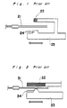
- Magneto-optical disk devices such as are conventionally known are shown in Fig. 1 and Fig. 2.
- the magneto-optical disk device shown in Fig. 1 is a device in which the magnetic field coil 22 which applies a magnetic field to one side of the magneto-optical disk 21 is integrated with an optical head 23 which irradiates the other side of the magneto-optical disk 21 by means of a laser emissions port 24.
- This integrated assembly slides parallel to the surface of the magneto-optical disk in the directions indicated by the arrows.
- the magnetic field coil 22 and laser emissions port 24 sandwich the magneto-optical disk 21 in mutually opposing positions so that a magnetic field is applied by the magnetic field coil 22 to that part of the magneto-optical disk irradiated by the laser.
- the magneto-optical disk device shown in Fig. 2 is a device in which the magnetic field coil 32 is mounted to, for example, a cassette holder (not shown in the figure) for magneto-optical disk 31, and is of a size large enough to apply a magnetic field to the entire media area of the magneto-optical disk.
- the optical head 33 slides as does the optical head in the device shown in Fig. 2 parallel to the surface of the disk such that laser light from the laser emissions port 34 irradiates the magneto-optical disk 31.
- the magneto-optical disk is typically of a cassette type, space sufficient to load the cassette is required in a direction perpendicular to the magneto-optical disk surface.
- space for cassette loading is required between magnetic field coil 22 and the magneto-optical disk 21, and between laser emissions port 24 and the magneto-optical disk 21.
- magnetic field coil 22 cannot be positioned any closer than a fixed distance from the magneto-optical disk. Therefore, the magnetic field coil must be of a size sufficiently large to apply from this fixed position a magnetic field of the required strength to magneto-optical disk 21. Thus, this magnetic field coil cannot be made smaller and the weight thus cannot be further reduced, and the access speed of the optical head thus becomes slower.
- the magnetic field coil 32 is mounted to the cassette holder and moves in conjunction with the cassette during cassette loading, extra cassette loading space between the magnetic field coil 32 and magneto-optical disk is not required in a magneto-optical disk device, but the magnetic field coil 32 must be of a size sufficient to apply a magnetic field to the entire media area of the magneto-optical disk.
- the current flowing through the coil is greater, the amount of heat created is greater, and the power consumption is greater.
- the present invention has been developed with a view to substantially solving the above described disadvantages and has for its essential object to provide an improved magneto-optical disk device of the type in which the magnetic field coil and optical head are integrated and slide in conjunction with each other such that the magnetic field coil can be brought close to the magneto-optical disk and the size and weight of the magnetic field coil can be minimized.
- a magneto-optical disk device for receiving a magneto-optical disk housed in a cassette and for driving the magneto-optical disk by a disk drive motor to read/write the disk, comprises a movable cassette carrier having a top plate for receiving the cassette therein, a read/write head located under the cassette carrier, a magnetic field coil slidably mounted on the top plate above the read/write head to move in a direction parallel to the movement of the read/write head, a pole extending approximately perpendicular from the read/write head at a position offset from the cassette carrier, and an arm having one end slidably mounted on the pole and other end fixedly connected to the magnetic field coil.
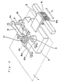
- reference number 1 is a cassette holder for a magneto-optical disk, a detail of which will be described later in connection with Fig. 4, and 2 is a read/write head comprised of a laser emissions port 3 and located under the cassette holder 1.
- the read/write head 2 is an optical head which irradiates the bottom surface of an inserted magneto-optical disk from laser emissions port 3 to write information to the magneto-optical disk or to read information from the disk.
- the read/write head 2 has a horizontal arm member 5 which extends outwardly and supports coil 6a of a linear motor 6, so that the movement of coil 6a as indicated by the arrow X makes read/write head 2 slide in the same directions parallel to the surface of cassette holder 1.
- a solid pole 7, serving as a first support member, is fixedly and approximately vertically mounted on read/write head 2 at one end portion thereof.
- a coil holder 8, which is a second support member, has a hole formed at one end 8a thereof so that coil holder 8 is slidably mounted on the solid pole 7.
- coil holder 8 may slide in a direction perpendicular to the surface of cassette holder 1.
- the other end 8b of coil holder 8 has a T-shaped section slidably supported by two parallel guide rods 10a and 10b which are fixedly mounted on cassette holder 1, as will be described in detail later in connection with Fig. 4.
- Each of guide rods 10a and 10b extends in the direction of read/write head 2 travel (the directions indicated by the arrow X) so that coil holder 8 slides along the guide rods freely in the direction of the arrow X together with the read/write head 2.
- a magnetic field coil 11 is mounted on T-shaped section 8b such that the axis of coil 11 is aligned with the axis of laser emissions port 3.
- Magnetic field coil 11 when excited applies a magnetic field to the surface of an loaded magneto-optical disk.
- electric current is supplied to magnetic field coil 11 by means of flexible cable 12, which supplies current for magnetic field generation.
- Coil holder 8 is tiered such that a portion connected to T-shaped section 8b is elevated so that that portion is held away from the magneto-optical disk to avoid any influence of the magnetic force to the disk.
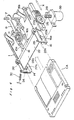
- cassette holder 1 which comprises opposite side plates 14 and 16 which are fixedly connected to a casing of a disk player (not shown).
- Each side plate such as side plate 16 is formed with two L-shaped grooves 16a and 16b, each groove having a long groove portion extending parallel to arrow X and a short groove portion extending perpendicular to arrow X at right end (when viewed in Fig. 4) of the long groove portion.
- Each side plate also has a circle opening formed closely adjacent the upper side edge thereof for receiving a shaft 18.
- shaft 18 is rotatably inserted in said circle opening and extends between side plates 14 and 16.
- a gear 20 is fixedly mounted on shaft 18 adjacent side plate 14.
- a similar gear is provided on shaft 18 adjacent side plate 16.
- cassette carrier plate 22 having a top plate 22a on which guide rods 10a and 10b are fixedly mounted by suitable holders provided at opposite ends of each rod.
- Cassette carrier plate 22 also has side rails 22b and 22c at opposite sides adjacent side plates 14 and 16 so as to slidingly receive a cassette CA between the rails.
- L-shaped gear plate 24 and 26 are fixedly attached to the side rails 22b and 22c, respectively.
- Each gear plate, such as 24, has gear teeth formed along its upper side face of the longer portion extending parallel to rail 22b and also on its side face of the short portion extending perpendicularly to rail 22b.
- the gear teeth formed on plate 24 engages gear 20, thus, rack and pinion arrangement is formed by plate 24 and gear 20.
- the same rack and pinion arrangement is provided on the opposite rail 22c.
- Pins 22d and 22e are fixedly mounted on rail 22c extending outwardly through grooves 16a and 16b. Similar pins are fixedly mounted on other rail 22b in a similar manner.
- a worm wheel gear 26 which engages with an worm gear 28 mounted on a motor 30.
- Motor 30 is firmly mounted on side plate 16.
- shaft 18 rotates to rotate pinion 20.
- cassette carrier plate 22, together with plates 24 and 26, moves in the direction of arrow X relatively to side plates 14 and 16, and then, when pinion 20 engages with short upright rack portion, the same moves downwardly towards read/write head 2.
- motor 30 rotates in the reverse direction, or a suitable return spring 32 is provided.
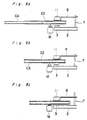
- cassette carrier plate 22 In operation, after inserting the magneto-optical disk (cassette CA) in cassette carrier plate 22, as diagrammatically shown in Figs. 5a and 5b, motor 30 rotates in the forward direction, so that cassette carrier plate 22 is moved towards pole 7 to have the magneto-optical disk above a disk drive motor M, that is, to have the axis of the magneto-optical disk approximately in alignment with the axis of the disk drive motor M, and then, the cassette carrier plate 22 is further moved downward, as the pins 22d and 22e are guided along grooves 16a and 16b. Accordingly, cassette CA is shifted to a loaded position, as shown in Fig. 5c, in which the disk engages with the motor M. By the downward movement of cassette carrier plate 22, magnetic field coil 11 also moves down by the sliding of coil holder 8 along pole 7. Thus, cassette CA is held closely between magnetic field coil 11 and laser emission port 3.
- read/write head 2 is slid in the direction of the arrow X by linear motor 6, so that laser emission port 3 and magnetic field coil 11, closely sandwiching the cassette CA, moves together in the radial direction of the disk.
- the recording is carried out such that the magneto-optical disk is irradiated by laser light from the laser emissions port 3 of read/write head 2, and a magnetic field is also applied by magnetic field coil 11 to that part of the magneto-optical disk irradiated by the laser light.
- coil holder 8 to which is mounted magnetic field coil 11 descends in conjunction with cassette holder 1, magnetic field coil 11 can be brought in close juxtaposition to the magneto-optical disk. Therefore, the coil can be made smaller when compared with that of a conventional magneto-optical disk device in which a loading space is required between the non-descending magnetic field coil and magneto-optical disk. As a result, the weight of the magnetic field coil is reduced, and the access speed is increased. Furthermore, because the coil impedance is reduced, the magnetic field inversion rate and application rate are increased, and a high frequency enabling data overwriting can be achieved. Moreover, the current flowing through the magnetic field coil is reduced, and heat generation and power consumption are reduced.
Applications Claiming Priority (2)
| Application Number | Priority Date | Filing Date | Title |
|---|---|---|---|
| JP63087654A JPH0695405B2 (ja) | 1988-04-07 | 1988-04-07 | 光磁気デイスク装置 |
| JP87654/88 | 1988-04-07 |
Publications (3)
| Publication Number | Publication Date |
|---|---|
| EP0336423A2 true EP0336423A2 (de) | 1989-10-11 |
| EP0336423A3 EP0336423A3 (en) | 1990-05-16 |
| EP0336423B1 EP0336423B1 (de) | 1995-02-01 |
Family
ID=13920946
Family Applications (1)
| Application Number | Title | Priority Date | Filing Date |
|---|---|---|---|
| EP89106080A Expired - Lifetime EP0336423B1 (de) | 1988-04-07 | 1989-04-06 | Magneto-optisches Plattengerät |
Country Status (4)
| Country | Link |
|---|---|
| US (1) | US5027334A (de) |
| EP (1) | EP0336423B1 (de) |
| JP (1) | JPH0695405B2 (de) |
| DE (1) | DE68920897T2 (de) |
Cited By (4)
| Publication number | Priority date | Publication date | Assignee | Title |
|---|---|---|---|---|
| US5111441A (en) * | 1990-02-06 | 1992-05-05 | Sony Corporation | Apparatus for generating magnetic field varying in response to an information signal |
| EP0475595A3 (en) * | 1990-08-24 | 1992-10-14 | Sony Corporation | Recording and/or reproducing apparatus for optical discs |
| US5179544A (en) * | 1989-03-28 | 1993-01-12 | U.S. Philips Corporation | Control system for the magnetic head of a magneto-optical disc apparatus |
| EP0554065B1 (de) * | 1992-01-27 | 1998-07-15 | Sony Corporation | Schreib-/Lese-Plattenspeicher |
Families Citing this family (17)
| Publication number | Priority date | Publication date | Assignee | Title |
|---|---|---|---|---|
| JPH0340250A (ja) * | 1989-07-06 | 1991-02-21 | Matsushita Electric Ind Co Ltd | 光磁気ディスクおよび光磁気ディスク装置 |
| JP3038754B2 (ja) * | 1990-01-20 | 2000-05-08 | ソニー株式会社 | 光磁気ディスクの記録装置 |
| US5258965A (en) * | 1990-02-28 | 1993-11-02 | Konica Corporation | Photo-magnetic disk driving apparatus |
| USRE35608E (en) * | 1990-04-28 | 1997-09-16 | Sony Corporation | Recording and/or reproducing apparatus for using magneto-optical disc |
| US5247496A (en) * | 1990-04-28 | 1993-09-21 | Sony Corporation | Recording and/or reproducing apparatus for using magneto-optical disc |
| US5343447A (en) * | 1990-05-23 | 1994-08-30 | Olympus Optical Co., Ltd. | Self-cooling optomagnetic disk device with locking internal mechanism |
| JP2641984B2 (ja) * | 1990-11-29 | 1997-08-20 | 群馬日本電気株式会社 | 光磁気ディスク装置 |
| JP3077220B2 (ja) * | 1991-02-23 | 2000-08-14 | ソニー株式会社 | 記録再生装置 |
| JP3428030B2 (ja) * | 1991-05-28 | 2003-07-22 | ソニー株式会社 | ディスク記録及び/又は再生装置 |
| JPH04351784A (ja) * | 1991-05-28 | 1992-12-07 | Sony Corp | ディスク記録及び/又は再生装置 |
| JPH05174390A (ja) * | 1991-06-21 | 1993-07-13 | Sony Corp | 光学ブロックの支持機構 |
| JPH0512737A (ja) * | 1991-07-02 | 1993-01-22 | Matsushita Electric Ind Co Ltd | 記録再生装置 |
| US5329503A (en) * | 1991-10-31 | 1994-07-12 | Sony Corporation | Magneto-optical disc recording/reproducing apparatus |
| US5428583A (en) * | 1991-10-31 | 1995-06-27 | Sony Corporation | Magneto-optical disc recording/reproducing apparatus |
| JP3018686B2 (ja) * | 1991-11-15 | 2000-03-13 | ソニー株式会社 | 光学ピックアップ装置の支持機構 |
| JPH06195796A (ja) * | 1992-08-28 | 1994-07-15 | Canon Inc | 光磁気記録用磁気ヘッドおよび光磁気記録装置 |
| US5360764A (en) * | 1993-02-16 | 1994-11-01 | The United States Of America, As Represented By The Secretary Of Commerce | Method of fabricating laser controlled nanolithography |
Family Cites Families (9)
| Publication number | Priority date | Publication date | Assignee | Title |
|---|---|---|---|---|
| JPS60226044A (ja) * | 1984-04-24 | 1985-11-11 | Sony Corp | 光磁気記録装置 |
| JPS60251541A (ja) * | 1984-05-28 | 1985-12-12 | Matsushita Electric Ind Co Ltd | 光学式記録再生装置 |
| JPS6111977A (ja) * | 1984-06-28 | 1986-01-20 | Toshiba Corp | 光磁気記録体 |
| JPS61115256A (ja) * | 1984-11-09 | 1986-06-02 | Hitachi Ltd | 光磁気デイスク装置 |
| JPS61170940A (ja) * | 1985-01-24 | 1986-08-01 | Mitsubishi Electric Corp | 光磁気記録再生消去装置 |
| JPH06103549B2 (ja) * | 1986-02-12 | 1994-12-14 | ソニー株式会社 | 光磁気記録装置 |
| JP2566924B2 (ja) * | 1986-07-14 | 1996-12-25 | キヤノン株式会社 | 光磁気記録装置 |
| US4914647A (en) * | 1986-08-25 | 1990-04-03 | Kabushiki Kaisha Toshiba | Optical disc player |
| JPS63291237A (ja) * | 1987-05-21 | 1988-11-29 | Mitsubishi Electric Corp | 光磁気記録再生用情報担体装置 |
-
1988
- 1988-04-07 JP JP63087654A patent/JPH0695405B2/ja not_active Expired - Fee Related
-
1989
- 1989-04-06 EP EP89106080A patent/EP0336423B1/de not_active Expired - Lifetime
- 1989-04-06 US US07/334,149 patent/US5027334A/en not_active Expired - Lifetime
- 1989-04-06 DE DE68920897T patent/DE68920897T2/de not_active Expired - Lifetime
Cited By (5)
| Publication number | Priority date | Publication date | Assignee | Title |
|---|---|---|---|---|
| US5179544A (en) * | 1989-03-28 | 1993-01-12 | U.S. Philips Corporation | Control system for the magnetic head of a magneto-optical disc apparatus |
| US5111441A (en) * | 1990-02-06 | 1992-05-05 | Sony Corporation | Apparatus for generating magnetic field varying in response to an information signal |
| EP0475595A3 (en) * | 1990-08-24 | 1992-10-14 | Sony Corporation | Recording and/or reproducing apparatus for optical discs |
| US5309421A (en) * | 1990-08-24 | 1994-05-03 | Sony Corporation | Recording and/or reproducing apparatus for optical disk |
| EP0554065B1 (de) * | 1992-01-27 | 1998-07-15 | Sony Corporation | Schreib-/Lese-Plattenspeicher |
Also Published As
| Publication number | Publication date |
|---|---|
| EP0336423A3 (en) | 1990-05-16 |
| US5027334A (en) | 1991-06-25 |
| DE68920897T2 (de) | 1995-06-22 |
| JPH0695405B2 (ja) | 1994-11-24 |
| DE68920897D1 (de) | 1995-03-16 |
| EP0336423B1 (de) | 1995-02-01 |
| JPH01258252A (ja) | 1989-10-16 |
Similar Documents
| Publication | Publication Date | Title |
|---|---|---|
| EP0336423A2 (de) | Magneto-optisches Plattengerät | |
| US5379170A (en) | Dynamically adjustable head positioning mechanism for tape drives | |
| US20010008473A1 (en) | Cartridge handling system having shaped cartridge storage configuration | |
| DE69231192T2 (de) | Plattenaufzeichnungs- und/oder -wiedergabegerät | |
| EP0397262B1 (de) | Plattenspieler sowie Ladevorrichtung für den Plattenspieler | |
| JPH10106115A (ja) | チェンジャー型ディスク再生装置 | |
| US7027249B2 (en) | Data erasing apparatus | |
| US5335124A (en) | Disk drive | |
| US4730226A (en) | Actuator carriage with "splayed-bearing" array | |
| US20050177838A1 (en) | Disk apparatus | |
| JPH06325521A (ja) | ディスク装置 | |
| KR950003174B1 (ko) | 광자기 기록장치 | |
| JP3812825B2 (ja) | 磁気ヘッド装置 | |
| JP2901457B2 (ja) | 光磁気ディスクローディング機構 | |
| JP2795584B2 (ja) | 光磁気ディスクドライブ装置 | |
| JPH0479092A (ja) | ディスク装置 | |
| JPH07169166A (ja) | 情報処理装置 | |
| JP2003141791A (ja) | 光磁気記録再生装置 | |
| JPH0479078A (ja) | ディスク装置 | |
| JPH0676408A (ja) | 光磁気ディスク装置 | |
| JPH0714180A (ja) | 光学ピックアップ装置のキャリッジ駆動装置 | |
| JPH08171782A (ja) | 情報記録媒体再生装置 | |
| JP2003272332A (ja) | 磁気ヘッド装置 | |
| JPH05274767A (ja) | ディスク装置 | |
| JPS62149066A (ja) | 光デイスクの交換装置 |
Legal Events
| Date | Code | Title | Description |
|---|---|---|---|
| PUAI | Public reference made under article 153(3) epc to a published international application that has entered the european phase |
Free format text: ORIGINAL CODE: 0009012 |
|
| 17P | Request for examination filed |
Effective date: 19890406 |
|
| AK | Designated contracting states |
Kind code of ref document: A2 Designated state(s): DE FR GB IT |
|
| PUAL | Search report despatched |
Free format text: ORIGINAL CODE: 0009013 |
|
| AK | Designated contracting states |
Kind code of ref document: A3 Designated state(s): DE FR GB IT |
|
| 17Q | First examination report despatched |
Effective date: 19930224 |
|
| GRAA | (expected) grant |
Free format text: ORIGINAL CODE: 0009210 |
|
| AK | Designated contracting states |
Kind code of ref document: B1 Designated state(s): DE FR GB IT |
|
| REF | Corresponds to: |
Ref document number: 68920897 Country of ref document: DE Date of ref document: 19950316 |
|
| ET | Fr: translation filed | ||
| ITF | It: translation for a ep patent filed | ||
| PLBE | No opposition filed within time limit |
Free format text: ORIGINAL CODE: 0009261 |
|
| STAA | Information on the status of an ep patent application or granted ep patent |
Free format text: STATUS: NO OPPOSITION FILED WITHIN TIME LIMIT |
|
| 26N | No opposition filed | ||
| REG | Reference to a national code |
Ref country code: GB Ref legal event code: IF02 |
|
| PGFP | Annual fee paid to national office [announced via postgrant information from national office to epo] |
Ref country code: FR Payment date: 20080312 Year of fee payment: 20 Ref country code: DE Payment date: 20080411 Year of fee payment: 20 |
|
| PGFP | Annual fee paid to national office [announced via postgrant information from national office to epo] |
Ref country code: IT Payment date: 20080428 Year of fee payment: 20 |
|
| PGFP | Annual fee paid to national office [announced via postgrant information from national office to epo] |
Ref country code: GB Payment date: 20080409 Year of fee payment: 20 |
|
| REG | Reference to a national code |
Ref country code: GB Ref legal event code: PE20 Expiry date: 20090405 |
|
| PG25 | Lapsed in a contracting state [announced via postgrant information from national office to epo] |
Ref country code: GB Free format text: LAPSE BECAUSE OF EXPIRATION OF PROTECTION Effective date: 20090405 |