EP0335301A2 - Procédé et dispositif de fabrication de corps de boîtes - Google Patents
Procédé et dispositif de fabrication de corps de boîtes Download PDFInfo
- Publication number
- EP0335301A2 EP0335301A2 EP89105372A EP89105372A EP0335301A2 EP 0335301 A2 EP0335301 A2 EP 0335301A2 EP 89105372 A EP89105372 A EP 89105372A EP 89105372 A EP89105372 A EP 89105372A EP 0335301 A2 EP0335301 A2 EP 0335301A2
- Authority
- EP
- European Patent Office
- Prior art keywords
- blank
- mandrel
- transport
- frame
- guide rods
- Prior art date
- Legal status (The legal status is an assumption and is not a legal conclusion. Google has not performed a legal analysis and makes no representation as to the accuracy of the status listed.)
- Granted
Links
Images


Classifications
-
- B—PERFORMING OPERATIONS; TRANSPORTING
- B21—MECHANICAL METAL-WORKING WITHOUT ESSENTIALLY REMOVING MATERIAL; PUNCHING METAL
- B21D—WORKING OR PROCESSING OF SHEET METAL OR METAL TUBES, RODS OR PROFILES WITHOUT ESSENTIALLY REMOVING MATERIAL; PUNCHING METAL
- B21D51/00—Making hollow objects
- B21D51/16—Making hollow objects characterised by the use of the objects
- B21D51/26—Making hollow objects characterised by the use of the objects cans or tins; Closing same in a permanent manner
- B21D51/2676—Cans or tins having longitudinal or helical seams
-
- B—PERFORMING OPERATIONS; TRANSPORTING
- B21—MECHANICAL METAL-WORKING WITHOUT ESSENTIALLY REMOVING MATERIAL; PUNCHING METAL
- B21D—WORKING OR PROCESSING OF SHEET METAL OR METAL TUBES, RODS OR PROFILES WITHOUT ESSENTIALLY REMOVING MATERIAL; PUNCHING METAL
- B21D43/00—Feeding, positioning or storing devices combined with, or arranged in, or specially adapted for use in connection with, apparatus for working or processing sheet metal, metal tubes or metal profiles; Associations therewith of cutting devices
- B21D43/02—Advancing work in relation to the stroke of the die or tool
- B21D43/04—Advancing work in relation to the stroke of the die or tool by means in mechanical engagement with the work
- B21D43/12—Advancing work in relation to the stroke of the die or tool by means in mechanical engagement with the work by chains or belts
-
- B—PERFORMING OPERATIONS; TRANSPORTING
- B31—MAKING ARTICLES OF PAPER, CARDBOARD OR MATERIAL WORKED IN A MANNER ANALOGOUS TO PAPER; WORKING PAPER, CARDBOARD OR MATERIAL WORKED IN A MANNER ANALOGOUS TO PAPER
- B31B—MAKING CONTAINERS OF PAPER, CARDBOARD OR MATERIAL WORKED IN A MANNER ANALOGOUS TO PAPER
- B31B50/00—Making rigid or semi-rigid containers, e.g. boxes or cartons
- B31B50/02—Feeding or positioning sheets, blanks or webs
- B31B50/04—Feeding sheets or blanks
- B31B50/044—Feeding sheets or blanks involving aligning
-
- B—PERFORMING OPERATIONS; TRANSPORTING
- B31—MAKING ARTICLES OF PAPER, CARDBOARD OR MATERIAL WORKED IN A MANNER ANALOGOUS TO PAPER; WORKING PAPER, CARDBOARD OR MATERIAL WORKED IN A MANNER ANALOGOUS TO PAPER
- B31B—MAKING CONTAINERS OF PAPER, CARDBOARD OR MATERIAL WORKED IN A MANNER ANALOGOUS TO PAPER
- B31B50/00—Making rigid or semi-rigid containers, e.g. boxes or cartons
- B31B50/02—Feeding or positioning sheets, blanks or webs
- B31B50/10—Feeding or positioning webs
- B31B50/104—Feeding or positioning webs involving aligning
-
- B—PERFORMING OPERATIONS; TRANSPORTING
- B31—MAKING ARTICLES OF PAPER, CARDBOARD OR MATERIAL WORKED IN A MANNER ANALOGOUS TO PAPER; WORKING PAPER, CARDBOARD OR MATERIAL WORKED IN A MANNER ANALOGOUS TO PAPER
- B31B—MAKING CONTAINERS OF PAPER, CARDBOARD OR MATERIAL WORKED IN A MANNER ANALOGOUS TO PAPER
- B31B50/00—Making rigid or semi-rigid containers, e.g. boxes or cartons
- B31B50/26—Folding sheets, blanks or webs
- B31B50/36—Folding sheets, blanks or webs by continuously feeding the sheets, blanks or webs to stationary members, e.g. plates, ploughs or cores
- B31B50/38—Folding sheets, blanks or webs by continuously feeding the sheets, blanks or webs to stationary members, e.g. plates, ploughs or cores the members being forming-tubes
- B31B50/40—Folding sheets, blanks or webs by continuously feeding the sheets, blanks or webs to stationary members, e.g. plates, ploughs or cores the members being forming-tubes acting internally
-
- B—PERFORMING OPERATIONS; TRANSPORTING
- B31—MAKING ARTICLES OF PAPER, CARDBOARD OR MATERIAL WORKED IN A MANNER ANALOGOUS TO PAPER; WORKING PAPER, CARDBOARD OR MATERIAL WORKED IN A MANNER ANALOGOUS TO PAPER
- B31B—MAKING CONTAINERS OF PAPER, CARDBOARD OR MATERIAL WORKED IN A MANNER ANALOGOUS TO PAPER
- B31B50/00—Making rigid or semi-rigid containers, e.g. boxes or cartons
- B31B50/26—Folding sheets, blanks or webs
- B31B50/36—Folding sheets, blanks or webs by continuously feeding the sheets, blanks or webs to stationary members, e.g. plates, ploughs or cores
- B31B50/38—Folding sheets, blanks or webs by continuously feeding the sheets, blanks or webs to stationary members, e.g. plates, ploughs or cores the members being forming-tubes
- B31B50/42—Folding sheets, blanks or webs by continuously feeding the sheets, blanks or webs to stationary members, e.g. plates, ploughs or cores the members being forming-tubes acting externally
Definitions
- the invention relates to a method for producing can bodies with a longitudinal seam from individual flat blanks, consisting of the following steps: Removal of a blank from a magazine, - gripping the blank at its rear edge and transporting the blank into a forming station, - continuous bending of the blank and - Forming the seam connection, and a device with a forearm, an outer mold, a device for guiding the edges of the can frame before the seam connection, two transport devices and a seam connection device for performing the method.
- the operating mode between the rounding of the frames and the leading out of the catch shell or the transfer area of the round machine is alternating.
- a high noise level is associated with this operating mode with constant braking by hard hitting and sudden driving.
- the performance is fundamentally limited by the constant changing of rounding and taking the cut out of the catch tray.
- the invention is based on the object of specifying a method and a device for producing can bodies with a longitudinal seam from individual, flat blanks, in which or with which the noise development can be reduced and / or the output can be increased.
- this object is characterized in that - That initially only the central area of the blank is formed around a mandrel into the final shape of the can frame and at the same time a central force or frictional engagement suitable for gripping the blank by means of transport is formed, the area which has been bent so far having a circumferential angle of 120 ... Has 190 ° and the lateral end areas extending beyond the curved area are left undeformed, - That the so far curved blank is grasped symmetrically on both sides in a further step and the still undeformed side areas of the blank are bent into the final shape with further continuous transport and precise guidance of the edges of the blank.
- the continuous, predominantly simultaneous transport in one direction and bending of the frame means that noisy braking and acceleration are eliminated. Since a blank can only be safely centered essentially in the flat state by lateral guides, the invention provides for a central force or frictional connection to be established between the transport means and the blank at the beginning of the bending, by means of which the pre-centered blank is continued is ensured.
- the further, lateral entrainment of the blank is - based on the circumference of the frame to be formed - provided at a point on the blank which is already bent. As a result, there are no relative movements between the blank and the driver pawls.
- the finished bent part of the blank can be supported and guided laterally at the same time as it is taken along.
- claim 2 describes with 180 ° an advantageous circumferential angle for the finished bent central region of the blank before the lateral detection.
- the measure proposed in claim 3 to capture the blank on its rear edge over a width that is at least 1/10 of the width corresponds to the cut, the guiding of the cut is stabilized in the plane.
- the device for carrying out the method is characterized in that that the forearm is already designed as a shaped mandrel in the region of the initial bending of the blank, the clear cross section of which corresponds to the finished can frame and that the shaped mandrel has a central recess on its underside in the longitudinal direction, that there is a circumferential means of transport arranged in the central longitudinal plane of the mandrel under the forming mandrel over a partial length thereof, with drivers reaching into the recess of the shaping mandrel and with elastic supports reaching from below to the shaping mandrel, - That the two inner sides of a first part of the outer mold from a plane that extends over at least one cut length, are gradually so far against the longitudinal center plane that they correspond to the lower part of a finished can frame, the outer mold having a central recess for Passage of the means of transport running in the longitudinal center plane, that the guide plane from which the outer mold emerges are assigned outer guide rails at a distance from the blank width, -
- a driver pawl of a means of transport can engage in the central recess arranged on the underside of the shaping mandrel, as a result of which the blank is reliably carried along by the molding tool.
- the central area of the blank is pressed somewhat downward into the elastic supports of the transport means. This creates a frictional engagement that achieves good lateral stability when guiding the blank through the molding tool.
- a plane is provided on which the blanks are centered by outer guide rails. Since the friction increases during further transport by the molding tool, it is further provided to equip the device with two lateral circumferential transport means which have catches and non-elastic supports with which the already bent area of the blank is laterally guided and supported.
- the one central recess of the mandrel on its underside can be assigned further symmetrically arranged recesses, in which parts of the driver pawl can also engage.
- the drivers of the transport means arranged in the central longitudinal plane preferably have a width of at least 1/10 of the blank width.
- the lateral transport means are preferably arranged in a plane extending through the axis of the can frame which has been bent so far.
- Claim 7 describes an advantageous embodiment of the mandrel.
- the mandrel consists of individual axially parallel guide rods, the outer lines of which correspond to the clear cross-section of the finished can frame, the central recess of the mandrel in particular being formed by the space between two guide rods which have the same lower position, and the guide rods being fastened to inner supporting elements indirectly connected to a frame are. Any further lower recesses can then be formed by the space between correspondingly adjacent guide rods.
- the upper guide rods of the mandrel can - seen in the direction of transport - start later than the lower guide rods.
- the outer mold advantageously consists of at least in its first part of guide rods, which over at least a cut length are arranged in one plane and then gradually upwards so far against the longitudinal center plane that the imaginary curve line enclosed by their inner lines corresponds to the lower part of the finished can frame, the guide rods being fastened to supporting elements connected to the frame.
- the second part of the outer mold which further develops the can bodies to the final shape, can consist of guide rods and / or rollers.
- the guide rods and the rollers of the outer molding tool are each assigned to a right and left upper and a lower roller guide tool, which are each individually adjustable.
- the rollers of the outer molding tool preferably have a concave contour which is matched to the outer contour of the curved frame.
- the transport means arranged under the mandrel in its longitudinal center plane is designed as a double roller chain.
- the height of the transport device can be adjusted by means of lifting elements in order to adjust the transport device arranged under the forming mandrel in its longitudinal center plane to different can diameters and to adjust the distance between the chain supports and the forming mandrel.
- the lateral transport means are designed as single roller chains and are radial in height by means of lifting means and by sliding elements adjustable. In order to align the cutting edges precisely in height, a lower and an upper skid is arranged at the outlet end of the grooved rail.
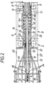
- the device for transporting and guiding can blanks Z and for forming them into can bodies extends over a forming section F and over a guiding section in front and behind.
- the molding section has a first and second transport device 1 and 2, a shaping mandrel 6, rod-shaped and roller-shaped outer shaping and guiding tools 24, 25, 31 to 33 and 42 to 44 and a grooved rail 38.
- the first transport device 1 takes over the advance of the can blanks (hereinafter also only briefly: blanks) Z from a magazine stacker known per se (not shown here) and transfers it to the second approximately in the middle of the molding section F.
- Transport device 2 is a magazine stacker known per se (not shown here)
- the first transport device 1 consists essentially of a double roller chain 3 running in the central longitudinal plane M of the molds with driver pawls 4 and elastic chain supports 5 arranged between the driver pawls. To adjust this transport device 1 to different can diameters D and to adjust the distance between the chain supports 5 and the (Dependent on the can diameter) shaped mandrel 6, the transport device 1 is adjustable in height by means of lifting elements 7.
- the second transport device 2 consists of mirror-image same feed chain drives 8 and 9, which are arranged laterally opposite one another from the forming mandrel 6 in one plane.
- drivers 11 and non-elastic supports 12 are fastened, which serve to feed or to support and guide the blanks Z which are already fully formed in the lower or middle region.
- the chains 10 and their drivers 11 are adjustable to compensate for division errors and other manufacturing tolerances on mutual alignment.
- the feed chain drives 8, 9 can be adjusted radially or horizontally for adaptation to the respective can diameter D by means of lifting elements 13 and by means of sliding elements 49.
- the shaping mandrel 6 consists of a multiplicity of round bars 14, 15, which are attached to the lower and upper support elements 16, 17 in a circular manner, ie forming an (imaginary) perimeter.
- the round bars 14, 15 have different lengths.
- the lowest round rods 15 are the longest and are already present at the beginning of the molding section F.
- the other round bars 14 and 15 - seen in the feed direction - are added.
- the uppermost round bars 15 are the shortest and begin shortly before the second transport device 2.
- the height of the shaping mandrel 6 can be changed to a small extent and can thus be set precisely to a predeterminable can diameter D.
- the support elements 16, 17 are fastened in a forearm profile 18 with an integrated cable and hose channel 19.
- the forearm profile 18 is screwed onto the frame 21 via an intermediate piece 20.
- FIG. 3 shows a section at the beginning of the molding section F.
- the blank Z lies on bars 24, 25 of a right or left guide cage fastened to support elements 22, 23 and on the elastic chain supports 5 of the first transport device 1.
- the rods 24, 25 are still arranged horizontally.
- the support members 22, 23 are connected via right and left supports 22 ', 23' and fastened to the frame 21 via these.
- the centering and alignment of the blank Z is carried out by lateral guides 26, 27, which can be adjusted in the distance and in their direction sensitively.
- the blank Z is gripped by a pawl 4.
- the pawl 4 (as 3 and 4) formed with three projections, so that the blank Z is detected over a certain width. The projections of the pawl 4 partially grip between the
- the two lateral guide baskets 22/24 and 23/25 essentially end with the first transport device 1.
- the blank Z in its central region is bent over a circumference of approximately 180 °.
- the blank now lies against the complete lower half of the forming mandrel 6 consisting of the rods 15.
- the two undeformed side parts of the blank Z which still correspond to a circumferential length of about 90 ° or ( ⁇ / 4) D, are tangentially adjacent to the central circular region of the blank with the radius D / 2.
- the feed of the blank Z from the second transport device 2 with the two Feed chain drives 8, 9 taken over, their rigid supports 12 taking over the lateral guidance of the blank Z in a horizontal orientation instead of one of the guide rods.
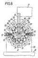
- FIG. 6 shows in a section - further away in the feed direction - along the line VI-VI in FIG. 1, a lower rod guide tool with guide rods 31 fastened to support elements 28 and two lateral upper rod guide tools with guide rods 32 or fastened to support elements 29, 30. 33 of a second part of the outer mold.
- the guide rods 31 of the lower rod guide tool run parallel to the mandrel 6 and are set radially so that the blank Z bears against the rods 15 of the lower part of the mandrel 6.
- the guide rods 31 - seen in the circumferential direction - are arranged offset to the rods 15 of the mandrel 6.
- the rods 32, 33 of the upper lateral rod guide tools are aligned convergingly so that the end regions of the blank Z are bent with the rods 14 during further advance into the upper region of the mandrel 6.
- the edges 34, 35 of the side parts of the blank Z dip into oppositely arranged grooves 36, 37 of a groove rail 38 which is arranged between the forearm profile 18 and the intermediate piece 20.
- the distance between the two grooves 36, 37 decreases continuously in the feed direction until the blank Z is completely bent around the shaping mandrel 6 and has assumed a closed circular cross section with the diameter D.
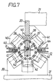
- the completely curved blank Z is outside of roller guide tools 39, 40, 41, the rigid supports 12 of the chains 10 of the feed chain drives 8, 9 and the guide grooves 36, 37 of the groove rail 38 fully enclosed (cf. the section shown in FIG. 7 just before the welding point S).
- the rollers 42 ... 44 of the roller guide tools 39 ... 41 are designed as so-called diabolo rollers and are precisely adapted to the circular cross section of the curved blank Z, which is also referred to as the frame.
- the rollers 42 ... 44 are individually adjustable in the radial direction, so that the edges 34, 35 of the rounded blank Z abut against one another with pressure 45.
- a height-adjustable skid 46 or 47 is arranged below and above the groove plane in order to align the cutting edges 34, 35 exactly in height.
- the welding point S When viewed downstream of the delivery flow, the welding point S is located directly behind the skids 46, 47, the welding being able to be carried out, for example, by a focused laser beam 48.
Landscapes
- Engineering & Computer Science (AREA)
- Mechanical Engineering (AREA)
- Making Paper Articles (AREA)
Applications Claiming Priority (2)
| Application Number | Priority Date | Filing Date | Title |
|---|---|---|---|
| DE3810611A DE3810611A1 (de) | 1988-03-29 | 1988-03-29 | Verfahren zum herstellen von dosenzargen und vorrichtung zum durchfuehren des verfahrens |
| DE3810611 | 1988-03-29 |
Publications (3)
| Publication Number | Publication Date |
|---|---|
| EP0335301A2 true EP0335301A2 (fr) | 1989-10-04 |
| EP0335301A3 EP0335301A3 (en) | 1990-09-19 |
| EP0335301B1 EP0335301B1 (fr) | 1994-07-06 |
Family
ID=6350946
Family Applications (1)
| Application Number | Title | Priority Date | Filing Date |
|---|---|---|---|
| EP89105372A Expired - Lifetime EP0335301B1 (fr) | 1988-03-29 | 1989-03-25 | Procédé et dispositif de fabrication de corps de boîtes |
Country Status (3)
| Country | Link |
|---|---|
| US (1) | US5061141A (fr) |
| EP (1) | EP0335301B1 (fr) |
| DE (1) | DE3810611A1 (fr) |
Cited By (2)
| Publication number | Priority date | Publication date | Assignee | Title |
|---|---|---|---|---|
| WO1993015856A1 (fr) * | 1992-02-14 | 1993-08-19 | Jammes Industrie S.A. | Lignes de production automatisee de viroles roulees soudees |
| WO1995024284A1 (fr) * | 1994-03-07 | 1995-09-14 | Elpatronic Ag | Dispositif de transport en serie de toles vers une station de traitement |
Families Citing this family (4)
| Publication number | Priority date | Publication date | Assignee | Title |
|---|---|---|---|---|
| CH686665A5 (de) * | 1992-08-26 | 1996-05-31 | Maegerle Karl Lizenz | Verfahren zur Herstellung von Rohrkoerper fuer Verpackungstuben. |
| DE4313871C2 (de) * | 1993-04-28 | 1999-07-22 | Krupp Kunststofftechnik Gmbh | Verfahren und Vorrichtung zum Herstellen von Dosenrümpfen aus kunststoffbeschichtetem Blech |
| DE4314462C2 (de) * | 1993-05-03 | 2001-02-08 | Krupp Kunststofftechnik Gmbh | Vorrichtung zum Senkrechtstellen von Dosenzargen |
| EP3572160A1 (fr) * | 2014-05-04 | 2019-11-27 | Belvac Production Machinery, Inc. | Ensemble bobine electromagnetique et son procede de fabrication |
Family Cites Families (14)
| Publication number | Priority date | Publication date | Assignee | Title |
|---|---|---|---|---|
| US11533A (en) * | 1854-08-15 | Machine foe | ||
| US3124872A (en) * | 1964-03-17 | Method and apparatus for severing a continuous | ||
| US1190351A (en) * | 1915-08-20 | 1916-07-11 | M J Ford | Machine for lock-joining tubes. |
| US2177104A (en) * | 1937-04-16 | 1939-10-24 | Battelle Memorial Institute | Method for manufacturing can bodies |
| US2432490A (en) * | 1944-10-30 | 1947-12-09 | Taylor Winfield Corp | Tubular body maker and conveyor |
| US2923304A (en) * | 1956-02-06 | 1960-02-02 | American Can Co | Apparatus for treating edge portions of can body blanks |
| US2864933A (en) * | 1957-02-19 | 1958-12-16 | W F And John Barnes Company | Apparatus for producing can bodies and welding side seams thereof |
| US3139012A (en) * | 1962-07-12 | 1964-06-30 | United Shoe Machinery Corp | Apparatus for forming containers |
| US3348510A (en) * | 1965-05-19 | 1967-10-24 | Frederick S Sillars | Method of and apparatus for manufacturing tubular bodies |
| US3430410A (en) * | 1966-11-21 | 1969-03-04 | Raymond A Heisler | Method for making eared tapered containers |
| FR2442100A2 (fr) * | 1978-11-27 | 1980-06-20 | Saurin Emmanuel | Procede de fabrication de corps tubulaires, notamment de boites de conserves, et dispositif pour l'execution de ce procede |
| DE2906692C2 (de) * | 1979-02-19 | 1985-02-21 | Mannesmann AG, 4000 Düsseldorf | Verfahren zur Herstellung von Schlitzrohren für eine Rohrschweißmaschine und Vorrichtung zur Durchführung des Verfahrens |
| IT8249012A0 (it) * | 1982-08-20 | 1982-08-20 | Fmi Mecfond Aziende Mecc | Saldatrice elettrica a resistenza per corpi scatolari con mezzi perfezionati per la calandratura della fascetta metallica, e il trasporto dei corpi calandrati fino alla stazione di saldatura |
| CH667411A5 (de) * | 1985-09-09 | 1988-10-14 | Elpatronic Ag | Zargenfuehrung an einer maschine zum stumpfschweissen von dosenzargen. |
-
1988
- 1988-03-29 DE DE3810611A patent/DE3810611A1/de active Granted
-
1989
- 1989-03-25 EP EP89105372A patent/EP0335301B1/fr not_active Expired - Lifetime
- 1989-03-29 US US07/330,178 patent/US5061141A/en not_active Expired - Fee Related
Cited By (3)
| Publication number | Priority date | Publication date | Assignee | Title |
|---|---|---|---|---|
| WO1993015856A1 (fr) * | 1992-02-14 | 1993-08-19 | Jammes Industrie S.A. | Lignes de production automatisee de viroles roulees soudees |
| FR2687336A1 (fr) * | 1992-02-14 | 1993-08-20 | Jammes Ind Sa | Ligne de production automatisee de viroles roulees soudees. |
| WO1995024284A1 (fr) * | 1994-03-07 | 1995-09-14 | Elpatronic Ag | Dispositif de transport en serie de toles vers une station de traitement |
Also Published As
| Publication number | Publication date |
|---|---|
| DE3810611A1 (de) | 1989-10-19 |
| US5061141A (en) | 1991-10-29 |
| DE3810611C2 (fr) | 1991-06-27 |
| EP0335301B1 (fr) | 1994-07-06 |
| EP0335301A3 (en) | 1990-09-19 |
Similar Documents
| Publication | Publication Date | Title |
|---|---|---|
| DE69316945T2 (de) | Verfahren und Vorrichtungen zum Biegen von Glasscheiben in horizontaler Lage | |
| DE2918724C2 (fr) | ||
| DE2918725C2 (fr) | ||
| DE19641509C2 (de) | Verfahren zum Transport eines Gürtelaufbaustreifens zum Aufbau eines Gürtels für einen Fahrzeugluftreifen | |
| DE4202540A1 (de) | Verfahren und vorrichtung zur herstellung definierter stapel gefalzter oder ungefalzter blaetter oder blattfoermiger gegenstaende | |
| EP0254028B1 (fr) | Dispositif d'étirage pour étirer continuellement un boudin de matériau en barres ou tubulaire | |
| EP1382402A2 (fr) | Dispositif pour la fabrication de tubes à partir de tôles | |
| DE2162874B2 (de) | Einrichtung zum Kleben eines Scheitelstreifens aus Kautschuk auf einen Wulstring für Luftreifen | |
| DE2124748B2 (de) | Einrichtung zum Entgraten des Halses von Hohlkörpern aus Kunststoff | |
| DE69601357T2 (de) | Automatische ziehvorrichtung | |
| EP1982777A1 (fr) | Machine à souder en continu destinée à souder une ébauche de tuyau | |
| EP0335301B1 (fr) | Procédé et dispositif de fabrication de corps de boîtes | |
| AT406744B (de) | Drahtbiegemaschine, insbesondere zum biegen von baustahldrähten | |
| DE1452281B2 (fr) | ||
| DE2906692A1 (de) | Verfahren zur herstellung von schlitzrohren fuer eine rohrschweissmaschine und vorrichtung zur durchfuehrung des verfahrens | |
| DE3146931C2 (de) | Vorrichtung für den Vorschub von Stabmaterial | |
| DE4336329C1 (de) | Vorrichtung und Verfahren zur Herstellung von Brezeln | |
| EP0349953A2 (fr) | Appareil pour travailler un matériau en forme de profil | |
| DE1923517A1 (de) | Verfahren zur Herstellung von Beuteln und Vorrichtung zur Durchfuehrung des Verfahrens | |
| EP0878555A1 (fr) | Dispositif pour guider des pièces | |
| DE2406498A1 (de) | Maschine zur muffenartigen aufweitung und abschraegung der rohrenden von kunststoffrohren | |
| CH671585A5 (fr) | ||
| EP0042450B1 (fr) | Procédé pour la fabrication d'enveloppes de pots d'échappement à joint longitudinal plié et dispositif pour la réalisation de ce procédé | |
| DE19707525C2 (de) | Vorrichtung zum seitlichen Umsetzen einer Fahrwegseitenbegrenzung | |
| DE4034266C2 (de) | Vorrichtung zum Transport und Zuführen von Rohren |
Legal Events
| Date | Code | Title | Description |
|---|---|---|---|
| PUAI | Public reference made under article 153(3) epc to a published international application that has entered the european phase |
Free format text: ORIGINAL CODE: 0009012 |
|
| AK | Designated contracting states |
Kind code of ref document: A2 Designated state(s): AT BE CH FR GB IT LI NL SE |
|
| PUAL | Search report despatched |
Free format text: ORIGINAL CODE: 0009013 |
|
| AK | Designated contracting states |
Kind code of ref document: A3 Designated state(s): AT BE CH FR GB IT LI NL SE |
|
| RHK1 | Main classification (correction) |
Ipc: B21D 43/12 |
|
| 17P | Request for examination filed |
Effective date: 19901214 |
|
| 17Q | First examination report despatched |
Effective date: 19911112 |
|
| RAP1 | Party data changed (applicant data changed or rights of an application transferred) |
Owner name: FRIED. KRUPP AG HOESCH-KRUPP |
|
| RBV | Designated contracting states (corrected) |
Designated state(s): CH LI |
|
| GRAA | (expected) grant |
Free format text: ORIGINAL CODE: 0009210 |
|
| AK | Designated contracting states |
Kind code of ref document: B1 Designated state(s): CH LI |
|
| PGFP | Annual fee paid to national office [announced via postgrant information from national office to epo] |
Ref country code: CH Payment date: 19950213 Year of fee payment: 7 |
|
| PLBE | No opposition filed within time limit |
Free format text: ORIGINAL CODE: 0009261 |
|
| STAA | Information on the status of an ep patent application or granted ep patent |
Free format text: STATUS: NO OPPOSITION FILED WITHIN TIME LIMIT |
|
| 26N | No opposition filed | ||
| PG25 | Lapsed in a contracting state [announced via postgrant information from national office to epo] |
Ref country code: LI Effective date: 19960331 Ref country code: CH Effective date: 19960331 |
|
| REG | Reference to a national code |
Ref country code: CH Ref legal event code: PL |