EP0335301A2 - Method and apparatus for making can bodies - Google Patents
Method and apparatus for making can bodies Download PDFInfo
- Publication number
- EP0335301A2 EP0335301A2 EP89105372A EP89105372A EP0335301A2 EP 0335301 A2 EP0335301 A2 EP 0335301A2 EP 89105372 A EP89105372 A EP 89105372A EP 89105372 A EP89105372 A EP 89105372A EP 0335301 A2 EP0335301 A2 EP 0335301A2
- Authority
- EP
- European Patent Office
- Prior art keywords
- blank
- mandrel
- transport
- frame
- guide rods
- Prior art date
- Legal status (The legal status is an assumption and is not a legal conclusion. Google has not performed a legal analysis and makes no representation as to the accuracy of the status listed.)
- Granted
Links
Images


Classifications
-
- B—PERFORMING OPERATIONS; TRANSPORTING
- B21—MECHANICAL METAL-WORKING WITHOUT ESSENTIALLY REMOVING MATERIAL; PUNCHING METAL
- B21D—WORKING OR PROCESSING OF SHEET METAL OR METAL TUBES, RODS OR PROFILES WITHOUT ESSENTIALLY REMOVING MATERIAL; PUNCHING METAL
- B21D51/00—Making hollow objects
- B21D51/16—Making hollow objects characterised by the use of the objects
- B21D51/26—Making hollow objects characterised by the use of the objects cans or tins; Closing same in a permanent manner
- B21D51/2676—Cans or tins having longitudinal or helical seams
-
- B—PERFORMING OPERATIONS; TRANSPORTING
- B21—MECHANICAL METAL-WORKING WITHOUT ESSENTIALLY REMOVING MATERIAL; PUNCHING METAL
- B21D—WORKING OR PROCESSING OF SHEET METAL OR METAL TUBES, RODS OR PROFILES WITHOUT ESSENTIALLY REMOVING MATERIAL; PUNCHING METAL
- B21D43/00—Feeding, positioning or storing devices combined with, or arranged in, or specially adapted for use in connection with, apparatus for working or processing sheet metal, metal tubes or metal profiles; Associations therewith of cutting devices
- B21D43/02—Advancing work in relation to the stroke of the die or tool
- B21D43/04—Advancing work in relation to the stroke of the die or tool by means in mechanical engagement with the work
- B21D43/12—Advancing work in relation to the stroke of the die or tool by means in mechanical engagement with the work by chains or belts
-
- B—PERFORMING OPERATIONS; TRANSPORTING
- B31—MAKING ARTICLES OF PAPER, CARDBOARD OR MATERIAL WORKED IN A MANNER ANALOGOUS TO PAPER; WORKING PAPER, CARDBOARD OR MATERIAL WORKED IN A MANNER ANALOGOUS TO PAPER
- B31B—MAKING CONTAINERS OF PAPER, CARDBOARD OR MATERIAL WORKED IN A MANNER ANALOGOUS TO PAPER
- B31B50/00—Making rigid or semi-rigid containers, e.g. boxes or cartons
- B31B50/02—Feeding or positioning sheets, blanks or webs
- B31B50/04—Feeding sheets or blanks
- B31B50/044—Feeding sheets or blanks involving aligning
-
- B—PERFORMING OPERATIONS; TRANSPORTING
- B31—MAKING ARTICLES OF PAPER, CARDBOARD OR MATERIAL WORKED IN A MANNER ANALOGOUS TO PAPER; WORKING PAPER, CARDBOARD OR MATERIAL WORKED IN A MANNER ANALOGOUS TO PAPER
- B31B—MAKING CONTAINERS OF PAPER, CARDBOARD OR MATERIAL WORKED IN A MANNER ANALOGOUS TO PAPER
- B31B50/00—Making rigid or semi-rigid containers, e.g. boxes or cartons
- B31B50/02—Feeding or positioning sheets, blanks or webs
- B31B50/10—Feeding or positioning webs
- B31B50/104—Feeding or positioning webs involving aligning
-
- B—PERFORMING OPERATIONS; TRANSPORTING
- B31—MAKING ARTICLES OF PAPER, CARDBOARD OR MATERIAL WORKED IN A MANNER ANALOGOUS TO PAPER; WORKING PAPER, CARDBOARD OR MATERIAL WORKED IN A MANNER ANALOGOUS TO PAPER
- B31B—MAKING CONTAINERS OF PAPER, CARDBOARD OR MATERIAL WORKED IN A MANNER ANALOGOUS TO PAPER
- B31B50/00—Making rigid or semi-rigid containers, e.g. boxes or cartons
- B31B50/26—Folding sheets, blanks or webs
- B31B50/36—Folding sheets, blanks or webs by continuously feeding the sheets, blanks or webs to stationary members, e.g. plates, ploughs or cores
- B31B50/38—Folding sheets, blanks or webs by continuously feeding the sheets, blanks or webs to stationary members, e.g. plates, ploughs or cores the members being forming-tubes
- B31B50/40—Folding sheets, blanks or webs by continuously feeding the sheets, blanks or webs to stationary members, e.g. plates, ploughs or cores the members being forming-tubes acting internally
-
- B—PERFORMING OPERATIONS; TRANSPORTING
- B31—MAKING ARTICLES OF PAPER, CARDBOARD OR MATERIAL WORKED IN A MANNER ANALOGOUS TO PAPER; WORKING PAPER, CARDBOARD OR MATERIAL WORKED IN A MANNER ANALOGOUS TO PAPER
- B31B—MAKING CONTAINERS OF PAPER, CARDBOARD OR MATERIAL WORKED IN A MANNER ANALOGOUS TO PAPER
- B31B50/00—Making rigid or semi-rigid containers, e.g. boxes or cartons
- B31B50/26—Folding sheets, blanks or webs
- B31B50/36—Folding sheets, blanks or webs by continuously feeding the sheets, blanks or webs to stationary members, e.g. plates, ploughs or cores
- B31B50/38—Folding sheets, blanks or webs by continuously feeding the sheets, blanks or webs to stationary members, e.g. plates, ploughs or cores the members being forming-tubes
- B31B50/42—Folding sheets, blanks or webs by continuously feeding the sheets, blanks or webs to stationary members, e.g. plates, ploughs or cores the members being forming-tubes acting externally
Definitions
- the invention relates to a method for producing can bodies with a longitudinal seam from individual flat blanks, consisting of the following steps: Removal of a blank from a magazine, - gripping the blank at its rear edge and transporting the blank into a forming station, - continuous bending of the blank and - Forming the seam connection, and a device with a forearm, an outer mold, a device for guiding the edges of the can frame before the seam connection, two transport devices and a seam connection device for performing the method.
- the operating mode between the rounding of the frames and the leading out of the catch shell or the transfer area of the round machine is alternating.
- a high noise level is associated with this operating mode with constant braking by hard hitting and sudden driving.
- the performance is fundamentally limited by the constant changing of rounding and taking the cut out of the catch tray.
- the invention is based on the object of specifying a method and a device for producing can bodies with a longitudinal seam from individual, flat blanks, in which or with which the noise development can be reduced and / or the output can be increased.
- this object is characterized in that - That initially only the central area of the blank is formed around a mandrel into the final shape of the can frame and at the same time a central force or frictional engagement suitable for gripping the blank by means of transport is formed, the area which has been bent so far having a circumferential angle of 120 ... Has 190 ° and the lateral end areas extending beyond the curved area are left undeformed, - That the so far curved blank is grasped symmetrically on both sides in a further step and the still undeformed side areas of the blank are bent into the final shape with further continuous transport and precise guidance of the edges of the blank.
- the continuous, predominantly simultaneous transport in one direction and bending of the frame means that noisy braking and acceleration are eliminated. Since a blank can only be safely centered essentially in the flat state by lateral guides, the invention provides for a central force or frictional connection to be established between the transport means and the blank at the beginning of the bending, by means of which the pre-centered blank is continued is ensured.
- the further, lateral entrainment of the blank is - based on the circumference of the frame to be formed - provided at a point on the blank which is already bent. As a result, there are no relative movements between the blank and the driver pawls.
- the finished bent part of the blank can be supported and guided laterally at the same time as it is taken along.
- claim 2 describes with 180 ° an advantageous circumferential angle for the finished bent central region of the blank before the lateral detection.
- the measure proposed in claim 3 to capture the blank on its rear edge over a width that is at least 1/10 of the width corresponds to the cut, the guiding of the cut is stabilized in the plane.
- the device for carrying out the method is characterized in that that the forearm is already designed as a shaped mandrel in the region of the initial bending of the blank, the clear cross section of which corresponds to the finished can frame and that the shaped mandrel has a central recess on its underside in the longitudinal direction, that there is a circumferential means of transport arranged in the central longitudinal plane of the mandrel under the forming mandrel over a partial length thereof, with drivers reaching into the recess of the shaping mandrel and with elastic supports reaching from below to the shaping mandrel, - That the two inner sides of a first part of the outer mold from a plane that extends over at least one cut length, are gradually so far against the longitudinal center plane that they correspond to the lower part of a finished can frame, the outer mold having a central recess for Passage of the means of transport running in the longitudinal center plane, that the guide plane from which the outer mold emerges are assigned outer guide rails at a distance from the blank width, -
- a driver pawl of a means of transport can engage in the central recess arranged on the underside of the shaping mandrel, as a result of which the blank is reliably carried along by the molding tool.
- the central area of the blank is pressed somewhat downward into the elastic supports of the transport means. This creates a frictional engagement that achieves good lateral stability when guiding the blank through the molding tool.
- a plane is provided on which the blanks are centered by outer guide rails. Since the friction increases during further transport by the molding tool, it is further provided to equip the device with two lateral circumferential transport means which have catches and non-elastic supports with which the already bent area of the blank is laterally guided and supported.
- the one central recess of the mandrel on its underside can be assigned further symmetrically arranged recesses, in which parts of the driver pawl can also engage.
- the drivers of the transport means arranged in the central longitudinal plane preferably have a width of at least 1/10 of the blank width.
- the lateral transport means are preferably arranged in a plane extending through the axis of the can frame which has been bent so far.
- Claim 7 describes an advantageous embodiment of the mandrel.
- the mandrel consists of individual axially parallel guide rods, the outer lines of which correspond to the clear cross-section of the finished can frame, the central recess of the mandrel in particular being formed by the space between two guide rods which have the same lower position, and the guide rods being fastened to inner supporting elements indirectly connected to a frame are. Any further lower recesses can then be formed by the space between correspondingly adjacent guide rods.
- the upper guide rods of the mandrel can - seen in the direction of transport - start later than the lower guide rods.
- the outer mold advantageously consists of at least in its first part of guide rods, which over at least a cut length are arranged in one plane and then gradually upwards so far against the longitudinal center plane that the imaginary curve line enclosed by their inner lines corresponds to the lower part of the finished can frame, the guide rods being fastened to supporting elements connected to the frame.
- the second part of the outer mold which further develops the can bodies to the final shape, can consist of guide rods and / or rollers.
- the guide rods and the rollers of the outer molding tool are each assigned to a right and left upper and a lower roller guide tool, which are each individually adjustable.
- the rollers of the outer molding tool preferably have a concave contour which is matched to the outer contour of the curved frame.
- the transport means arranged under the mandrel in its longitudinal center plane is designed as a double roller chain.
- the height of the transport device can be adjusted by means of lifting elements in order to adjust the transport device arranged under the forming mandrel in its longitudinal center plane to different can diameters and to adjust the distance between the chain supports and the forming mandrel.
- the lateral transport means are designed as single roller chains and are radial in height by means of lifting means and by sliding elements adjustable. In order to align the cutting edges precisely in height, a lower and an upper skid is arranged at the outlet end of the grooved rail.
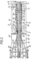
- the device for transporting and guiding can blanks Z and for forming them into can bodies extends over a forming section F and over a guiding section in front and behind.
- the molding section has a first and second transport device 1 and 2, a shaping mandrel 6, rod-shaped and roller-shaped outer shaping and guiding tools 24, 25, 31 to 33 and 42 to 44 and a grooved rail 38.
- the first transport device 1 takes over the advance of the can blanks (hereinafter also only briefly: blanks) Z from a magazine stacker known per se (not shown here) and transfers it to the second approximately in the middle of the molding section F.
- Transport device 2 is a magazine stacker known per se (not shown here)
- the first transport device 1 consists essentially of a double roller chain 3 running in the central longitudinal plane M of the molds with driver pawls 4 and elastic chain supports 5 arranged between the driver pawls. To adjust this transport device 1 to different can diameters D and to adjust the distance between the chain supports 5 and the (Dependent on the can diameter) shaped mandrel 6, the transport device 1 is adjustable in height by means of lifting elements 7.
- the second transport device 2 consists of mirror-image same feed chain drives 8 and 9, which are arranged laterally opposite one another from the forming mandrel 6 in one plane.
- drivers 11 and non-elastic supports 12 are fastened, which serve to feed or to support and guide the blanks Z which are already fully formed in the lower or middle region.
- the chains 10 and their drivers 11 are adjustable to compensate for division errors and other manufacturing tolerances on mutual alignment.
- the feed chain drives 8, 9 can be adjusted radially or horizontally for adaptation to the respective can diameter D by means of lifting elements 13 and by means of sliding elements 49.
- the shaping mandrel 6 consists of a multiplicity of round bars 14, 15, which are attached to the lower and upper support elements 16, 17 in a circular manner, ie forming an (imaginary) perimeter.
- the round bars 14, 15 have different lengths.
- the lowest round rods 15 are the longest and are already present at the beginning of the molding section F.
- the other round bars 14 and 15 - seen in the feed direction - are added.
- the uppermost round bars 15 are the shortest and begin shortly before the second transport device 2.
- the height of the shaping mandrel 6 can be changed to a small extent and can thus be set precisely to a predeterminable can diameter D.
- the support elements 16, 17 are fastened in a forearm profile 18 with an integrated cable and hose channel 19.
- the forearm profile 18 is screwed onto the frame 21 via an intermediate piece 20.
- FIG. 3 shows a section at the beginning of the molding section F.
- the blank Z lies on bars 24, 25 of a right or left guide cage fastened to support elements 22, 23 and on the elastic chain supports 5 of the first transport device 1.
- the rods 24, 25 are still arranged horizontally.
- the support members 22, 23 are connected via right and left supports 22 ', 23' and fastened to the frame 21 via these.
- the centering and alignment of the blank Z is carried out by lateral guides 26, 27, which can be adjusted in the distance and in their direction sensitively.
- the blank Z is gripped by a pawl 4.
- the pawl 4 (as 3 and 4) formed with three projections, so that the blank Z is detected over a certain width. The projections of the pawl 4 partially grip between the
- the two lateral guide baskets 22/24 and 23/25 essentially end with the first transport device 1.
- the blank Z in its central region is bent over a circumference of approximately 180 °.
- the blank now lies against the complete lower half of the forming mandrel 6 consisting of the rods 15.
- the two undeformed side parts of the blank Z which still correspond to a circumferential length of about 90 ° or ( ⁇ / 4) D, are tangentially adjacent to the central circular region of the blank with the radius D / 2.
- the feed of the blank Z from the second transport device 2 with the two Feed chain drives 8, 9 taken over, their rigid supports 12 taking over the lateral guidance of the blank Z in a horizontal orientation instead of one of the guide rods.
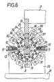
- FIG. 6 shows in a section - further away in the feed direction - along the line VI-VI in FIG. 1, a lower rod guide tool with guide rods 31 fastened to support elements 28 and two lateral upper rod guide tools with guide rods 32 or fastened to support elements 29, 30. 33 of a second part of the outer mold.
- the guide rods 31 of the lower rod guide tool run parallel to the mandrel 6 and are set radially so that the blank Z bears against the rods 15 of the lower part of the mandrel 6.
- the guide rods 31 - seen in the circumferential direction - are arranged offset to the rods 15 of the mandrel 6.
- the rods 32, 33 of the upper lateral rod guide tools are aligned convergingly so that the end regions of the blank Z are bent with the rods 14 during further advance into the upper region of the mandrel 6.
- the edges 34, 35 of the side parts of the blank Z dip into oppositely arranged grooves 36, 37 of a groove rail 38 which is arranged between the forearm profile 18 and the intermediate piece 20.
- the distance between the two grooves 36, 37 decreases continuously in the feed direction until the blank Z is completely bent around the shaping mandrel 6 and has assumed a closed circular cross section with the diameter D.
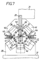
- the completely curved blank Z is outside of roller guide tools 39, 40, 41, the rigid supports 12 of the chains 10 of the feed chain drives 8, 9 and the guide grooves 36, 37 of the groove rail 38 fully enclosed (cf. the section shown in FIG. 7 just before the welding point S).
- the rollers 42 ... 44 of the roller guide tools 39 ... 41 are designed as so-called diabolo rollers and are precisely adapted to the circular cross section of the curved blank Z, which is also referred to as the frame.
- the rollers 42 ... 44 are individually adjustable in the radial direction, so that the edges 34, 35 of the rounded blank Z abut against one another with pressure 45.
- a height-adjustable skid 46 or 47 is arranged below and above the groove plane in order to align the cutting edges 34, 35 exactly in height.
- the welding point S When viewed downstream of the delivery flow, the welding point S is located directly behind the skids 46, 47, the welding being able to be carried out, for example, by a focused laser beam 48.
Landscapes
- Engineering & Computer Science (AREA)
- Mechanical Engineering (AREA)
- Making Paper Articles (AREA)
Abstract
Bei diesem Verfahren bzw. mit dieser Vorrichtung werden die Zuschnitte (Z) nach der Entnahme aus einem Magazin seitlich zentriert, an ihrer hinteren Kante mittig erfaßt und in eine Formstation (6, 24, 25) transportiert, in der zunächst der mittlere Bereich des Zuschnitts (Z) in seine endgültige Form (Durchmesser D) gebogen wird. Dabei wird ein mittiger Kraft- bzw. Reibschluß zwischen einem Transportmittel (1, 3, 5) und dem Zuschnitt (Z) hergestellt, um eine zuverlässige Führung auch des bereits teilweise gebogenen Zuschnitts zu erreichen. Zum weiteren Transportieren des Zuschnitts wird dieser von zwei seitlichen Transporteinrichtungen (2; 8, 9) an der Hinterkante im bereits fertig gebogenen Bereich erfaßt und unter genauem Führen der Kanten des Zuschnitts einer Nahtverbindungsstation (48) zugeführt. 
Description
Die Erfindung betrifft ein Verfahren zum Herstellen von Dosenzargen mit einer Längsnaht aus einzelnen ebenen Zuschnitten,
bestehend aus folgenden Schritten:
- Entnahme eines Zuschnitts aus einem Magazin,
- mittiges Erfassen des Zuschnitts an seiner Hinterkante und Transportieren des Zuschnitts in eine Formstation,
- kontinuierliches Biegen des Zuschnitts und
- Ausbilden der Nahtverbindung, und eine Vorrichtung mit einem Unterarm, einem äußeren Formwerkzeug, einer Einrichtung zur Führung der Kanten der Dosenzarge vor dem Nahtverbinden, zwei Transporteinrichtungen und einer Nahtverbindungseinrichtung zur Durchführung des Verfahrens.The invention relates to a method for producing can bodies with a longitudinal seam from individual flat blanks,
consisting of the following steps:
Removal of a blank from a magazine,
- gripping the blank at its rear edge and transporting the blank into a forming station,
- continuous bending of the blank and
- Forming the seam connection, and a device with a forearm, an outer mold, a device for guiding the edges of the can frame before the seam connection, two transport devices and a seam connection device for performing the method.
Zum Herstellen von mit einer Längsnaht versehenen i. allg. runden Dosenzargen gibt es zwei Wege: Das Herstellen aus einzelnen Zuschnitten und das Herstellen eines entsprechenden Rohres aus einem langen Band, von dem die Dosenzargen anschließend durch Abtrennen vereinzelt werden.For the production of i. There are two ways of generally round can bodies: the manufacture from individual blanks and the manufacture of a corresponding tube from a long strip, from which the can bodies are then separated by separation.
Beim Herstellen aus Zuschnitten werden diese einzeln aus einem Magazin entnommen und mit großer Geschwindigkeit durch einen sog. Rundapparat (vgl. z.B. DE-OS 33 30 171) geschickt, in dem der ebene Zuschnitt in eine runde Vorform überführt wird. Am Ende des Biegevorgangs fällt der gebogene Zuschnitt in eine sog. Fangschale, wo er bis zu einem vorübergehenden Stillstand abgebremst wird. Der gerundete Zuschnitt wird dann in seiner eigenen Achsrichtung, d.h. um 90° zur Bewegungsrichtung des ebenen Zuschnitts bis in den Rundapparat wieder aus dem Rundapparat beschleunigt und mit i. allg. deutlich höherer Geschwindigkeit als der Fügegeschwindigkeit aus der Fangschale in eine von einer äußeren Führungseinrichtung umgebenden Führungsschiene und weiter in eine Fügestation transportiert.When producing from blanks, these are individually removed from a magazine and sent at high speed through a so-called round apparatus (see, for example, DE-OS 33 30 171) in which the plane Is cut into a round preform. At the end of the bending process, the bent blank falls into a so-called catch tray, where it is braked until it stops temporarily. The rounded blank is then accelerated out of the circular apparatus in its own axial direction, ie by 90 ° to the direction of movement of the flat blank up to the circular apparatus and with i. generally significantly higher speed than the joining speed from the collecting tray into a guide rail surrounded by an outer guide device and further transported to a joining station.
Die Betriebsart zwischen dem Einrunden der Zargen und dem Herausführen aus der Fangschale bzw. dem Übergabebereich der Rundmaschine ist alternierend. Mit dieser Betriebsart mit ständigem Abbremsen durch hartes Anschlagen und schlagartigem Mitnehmen ist ein hoher Geräuschpegel verbunden. Außerdem ist die Leistung durch das ständige Wechseln von Einrunden und Herausführen des Zuschnitts aus der Fangschale prinzipiell begrenzt.The operating mode between the rounding of the frames and the leading out of the catch shell or the transfer area of the round machine is alternating. A high noise level is associated with this operating mode with constant braking by hard hitting and sudden driving. In addition, the performance is fundamentally limited by the constant changing of rounding and taking the cut out of the catch tray.
Das Herstellung von Rohren mit verschweißter Längsnaht, das anschließend in einer Abtrennstation zu einzelnen Dosenzargen zerteilt wird, ist beispielsweise in der DE-OS 29 47 445 beschrieben. Zum Formen wird das Band durch ein äußeres geschlossenes Formwerkzeug gezogen, das von einer weiteren Anfangsöffnung zu einer Ausgangsöffnung mit einem dem Dosendurchmesser entsprechenden Durchmesser trichterförmig konvergiert. Obwohl das kontinuierliche Formen eines Bandes sowohl hinsichtlich der Geräuschentwicklung als auch in bezug auf die Ausbringung an und für sich große Vorteile bietet, macht es Probleme, die zum Durchziehen des Blechs erforderlichen Kräfte außen an dem Blech angreifen zu lassen. Dabei kann das Band vor dem Formen und der Nahtbildung auch in Abständen, die der Zargenlänge entsprechen, mit Ritzlinien versehen werden, wobei das Vereinzeln in einzelne Zargen in einer sog. Trennstation erfolgt (vgl. z.B. US-PS 3 430 410).The production of tubes with a welded longitudinal seam, which is then cut into individual can bodies in a separation station, is described, for example, in DE-OS 29 47 445. For shaping, the band is drawn through an outer, closed shaping tool, which converges in a funnel shape from a further initial opening to an exit opening with a diameter corresponding to the can diameter. Although continuously forming a belt offers great advantages in terms of both noise and output in and of itself, it does pose problems that result in By pulling the sheet metal necessary forces to act on the outside of the sheet metal. The tape can also be provided with scoring lines at intervals corresponding to the frame length prior to shaping and seam formation, the separation into individual frames taking place in a so-called separation station (cf., for example, US Pat. No. 3,430,410).
Dem Formen von einzelnen Zuschnitten in einem äußeren trichterförmigen Werkzeug steht nicht nur entgegen, daß sich die Zuschnitte bei dem durch das Formwerkzeug bedingten Widerstand sehr leicht verkanten und damit eine genaue Führung unmöglich machen. Zudem stößt auch das Durchziehen der im Verhältnis zum äußeren Formwerkzeug kurzen Zuschnitte auf erhebliche Schwierigkeiten.The formation of individual blanks in an outer funnel-shaped tool is not only opposed to the fact that the blanks tilt very easily with the resistance caused by the shaping tool and thus make precise guidance impossible. In addition, pulling through the short blanks in relation to the outer molding tool also encounters considerable difficulties.
Der Erfindung liegt die Aufgabe zugrunde, ein Verfahren und eine Vorrichtung zum Herstellen von Dosenzargen mit einer Längsnaht aus einzelnen, ebenen Zuschnitten anzugeben, bei dem bzw. mit der die Geräuschentwicklung gemindert und/oder die Ausbringung gesteigert werden kann.The invention is based on the object of specifying a method and a device for producing can bodies with a longitudinal seam from individual, flat blanks, in which or with which the noise development can be reduced and / or the output can be increased.
Diese Aufgabe wird erfindungsgemäß dadurch gekennzeichnet,
- daß zunächst nur der mittlere Bereich des Zuschnitts um einen Formdorn in die endgültige Form der Dosenzarge und gleichzeitig ein zum Erfassen des Zuschnitts durch Transportmittel geeigneter mittiger Kraft bzw. Reibschluß ausgebildet wird, wobei der so weit fertig gebogene Bereich einen Umfangswinkel von 120...190° aufweist und die über den gebogenen Bereich hinausgehenden seitlichen Endbereiche unverformt belassen werden,
- daß der so weit gebogene Zuschnitt in einem weiteren Schritt symmetrisch an beiden Seiten erfaßt und die noch unverformten Seitenbereiche des Zuschnitts unter weiterem kontinuierlichen Transportieren und genauem Führen der Kanten des Zuschnitts in die endgültige Form gebogen zu werden.According to the invention, this object is characterized in that
- That initially only the central area of the blank is formed around a mandrel into the final shape of the can frame and at the same time a central force or frictional engagement suitable for gripping the blank by means of transport is formed, the area which has been bent so far having a circumferential angle of 120 ... Has 190 ° and the lateral end areas extending beyond the curved area are left undeformed,
- That the so far curved blank is grasped symmetrically on both sides in a further step and the still undeformed side areas of the blank are bent into the final shape with further continuous transport and precise guidance of the edges of the blank.
Durch das kontinuierliche, überwiegend gleichzeitige Transportieren in einer Richtung und Biegen der Zarge entfällt das geräuschträchtige Abbremsen und Beschleunigen. Da ein Zuschnitt im wesentlichen nur im ebenen Zustand durch seitliche Führungen sicher zu zentrieren ist, ist nach der Erfindung vorgesehen, mit dem Beginn des Biegens einen mittigen Kraft- bzw. Reibschluß zwischen dem Transportmittel und dem Zuschnitt herzustellen, durch den eine Weiterführung des vorzentrierten Zuschnitts sichergestellt wird. Die weitere, seitliche Mitnahme des Zuschnitts ist - bezogen auf den Umfang der zu formenden Zarge - an einer Stelle des Zuschnitts vorgesehen, die bereits fertig gebogen ist. Dadurch ergeben sich keinerlei Relativbewegungen zwischen dem Zuschnitt und den Mitnehmerklinken. Außerdem kann der fertig gebogene Teil des Zuschnitts gleichzeitig mit der Mitnahme auch seitlich abgestützt und geführt werden.The continuous, predominantly simultaneous transport in one direction and bending of the frame means that noisy braking and acceleration are eliminated. Since a blank can only be safely centered essentially in the flat state by lateral guides, the invention provides for a central force or frictional connection to be established between the transport means and the blank at the beginning of the bending, by means of which the pre-centered blank is continued is ensured. The further, lateral entrainment of the blank is - based on the circumference of the frame to be formed - provided at a point on the blank which is already bent. As a result, there are no relative movements between the blank and the driver pawls. In addition, the finished bent part of the blank can be supported and guided laterally at the same time as it is taken along.
Vorteilhafte Weiterbildungen der Erfindung sind in den Unteransprüchen beschrieben. So beschreibt der Anspruch 2 mit 180° einen vorteilhaften Umfangswinkel für den fertig gebogenen mittleren Bereich des Zuschnitts vor dem seitlichen Erfassen. Durch die im Anspruch 3 vorgeschlagene Maßnahme, den Zuschnitt an seiner hinteren Kante über eine Breite zu erfassen, die mindestens 1/10 der Bereite des Zuschnitts entspricht, wird das Führen des Zuschnitts in der Ebene stabilisiert.Advantageous developments of the invention are described in the subclaims. For example,
Die Vorrichtung zur Durchführung des Verfahrens ist dadurch gekennzeichnet,
- daß der Unterarm bereits im Bereich des anfänglichen Biegens des Zuschnitts als Formdorn ausgebildet ist, dessen lichter Querschnitt der fertigen Dosenzarge entspricht und daß der Formdorn an seiner Unterseite in Längsrichtung eine mittige Ausnehmung aufweist,
- daß sich unter dem Formdorn über eine Teillänge desselben ein in der Mittellängsebene des Formdorns angeordnetes umlaufendes Transportmittel mit in die Ausnehmung des Formdorns reichenden Mitnehmern und mit von unten bis an den Formdorn heranreichenden elastischen Auflagen befindet,
- daß die beiden Innenseiten eines ersten Teils des äußeren Formwerkzeugs aus einer Ebene, die über mindestens eine Zuschnittlänge reicht, allmählich soweit gegen die Längsmittelebene nach oben geführt sind, daß sie dem unteren Teil einer fertigen Dosenzarge entsprechen, wobei das äußere Formwerkzeug eine mittige Ausnehmung zum Durchgang des in der Längsmittelebene verlaufenden Transportmittels aufweist,
- daß der Führungsebene, aus der das äußere Formwerkzeug hervorgeht, äußere Führungsschienen im Abstand der Zuschnittbreite zugeordnet sind,
- daß sich dem in der Längsmittelebene verlaufenden Transportmittel und dem ersten Teil des äußeren Formwerkzeugs an jeder Seite ein umlaufendes Transportmittel mit Mitnehmerklinken und bis an den fertig gebogenen Teil der Dosenzarge heranreichenden nichtelastischen Auflagen und ein zweiter, die Dosenzargen bis zur endgültigen Form weiterbildender Teil des äußeren Führungswerkzeugs anschließt, wobei das äußere Führungswerkzeug seitliche Ausnehmungen zum Durchlaß der seitlichen Transportmittel aufweist und beide Transportmittel spiegelbildlich gleich ausgebildet sind.The device for carrying out the method is characterized in that
that the forearm is already designed as a shaped mandrel in the region of the initial bending of the blank, the clear cross section of which corresponds to the finished can frame and that the shaped mandrel has a central recess on its underside in the longitudinal direction,
that there is a circumferential means of transport arranged in the central longitudinal plane of the mandrel under the forming mandrel over a partial length thereof, with drivers reaching into the recess of the shaping mandrel and with elastic supports reaching from below to the shaping mandrel,
- That the two inner sides of a first part of the outer mold from a plane that extends over at least one cut length, are gradually so far against the longitudinal center plane that they correspond to the lower part of a finished can frame, the outer mold having a central recess for Passage of the means of transport running in the longitudinal center plane,
that the guide plane from which the outer mold emerges are assigned outer guide rails at a distance from the blank width,
- That in the longitudinal center plane of the transport means and the first part of the outer mold on each side a circumferential transport means with catches and reaching up to the finished bent part of the can frame non-elastic supports and a second part of the outer guide tool which further develops the can bodies to the final shape, the outer guide tool having lateral recesses for the passage of the lateral transport means and both transport means having the same mirror image.
In die an der Unterseite des Formdorns angeordnete mittige Ausnehmung kann eine Mitnehmerklinke eines Transportmittels eingreifen, wodurch eine sichere Mitnahme des Zuschnitts durch das Formwerkzeug gewährleistet ist. Beim Biegen des Zuschnitts um den Formdorn wird der mittige Bereich des Zuschnitts etwas nach unten in die elastischen Auflagen des Transportmittels gedrückt. Dadurch wird ein Reibschluß erzeugt, der eine gute seitliche Stabilität beim Führen des Zuschnitts durch das Formwerkzeug erreicht. Um den Zuschnitt in einem exakt ausgerichteten Zustand in das Formwerkzeug zu führen ist eine Ebene vorgesehen, auf der die Zuschnitte durch äußere Führungsschienen zentriert werden. Da sich die Reibung beim weiteren Transportieren durch das Formwerkzeug erhöht, ist weiter vorgesehen, die Vorrichtung mit zwei seitlichen umlaufenden Transportmitteln auszurüsten, die Mitnehmerklinken und nicht elastische Auflagen aufweisen, mit denen der bereits fertig gebogene Bereich des Zuschnitts seitlich geführt und abgestützt wird.A driver pawl of a means of transport can engage in the central recess arranged on the underside of the shaping mandrel, as a result of which the blank is reliably carried along by the molding tool. When the blank is bent around the mandrel, the central area of the blank is pressed somewhat downward into the elastic supports of the transport means. This creates a frictional engagement that achieves good lateral stability when guiding the blank through the molding tool. In order to guide the blank into the mold in an exactly aligned state, a plane is provided on which the blanks are centered by outer guide rails. Since the friction increases during further transport by the molding tool, it is further provided to equip the device with two lateral circumferential transport means which have catches and non-elastic supports with which the already bent area of the blank is laterally guided and supported.
Der einen mittigen Ausnehmung des Formdorns an seiner Unterseite können weitere symmetrisch angeordnete Ausnehmungen zugeordnet werden, in denen ebenfalls Teile der Mitnehmerklinke eingreifen können.The one central recess of the mandrel on its underside can be assigned further symmetrically arranged recesses, in which parts of the driver pawl can also engage.
Die Mitnehmer des in der Mittellängsebene angeordneten Transportmittels weisen vorzugsweise eine Breite von mindestens 1/10 der Zuschnittbreite auf.The drivers of the transport means arranged in the central longitudinal plane preferably have a width of at least 1/10 of the blank width.
Nach Anspruch 6 sind die seitlichen Transportmittel vorzugsweise in einer durch die Achse der soweit fertig gebogenen Dosenzarge verlaufenden Ebene angeordnet.According to
Anspruch 7 beschreibt eine vorteilhafte Ausbildung des Formdorns. Der Formdorn besteht aus einzelnen achsparallelen Führungsstäben, deren Außenlinien dem lichten Querschnitt der fertigen Dosenzarge entsprechen, wobei insbesondere die mittige Ausnehmung des Formdorns durch den Zwischenraum zweier eine gleich hohe untere Lage einnehmender Führungsstäbe gebildet wird und die Führungsstäbe an mittelbar mit einem Gestell verbundenen inneren Tragelementen befestigt sind. Etwaige weitere untere Ausnehmungen können dann durch den Zwischenraum entsprechend benachbarter Führungsstäbe gebildet sein.Claim 7 describes an advantageous embodiment of the mandrel. The mandrel consists of individual axially parallel guide rods, the outer lines of which correspond to the clear cross-section of the finished can frame, the central recess of the mandrel in particular being formed by the space between two guide rods which have the same lower position, and the guide rods being fastened to inner supporting elements indirectly connected to a frame are. Any further lower recesses can then be formed by the space between correspondingly adjacent guide rods.
Die oberen Führungsstäbe des Formdorns können - in Transportrichtung gesehen - später beginnen als die unteren Führungsstäbe.The upper guide rods of the mandrel can - seen in the direction of transport - start later than the lower guide rods.
Um den Formdorn der herzustellenden Dosenzarge genau anpassen zu können, wird nach Anspruch 9 vorgeschlagen, die unteren und oberen Führungsstäbe in der Höhe relativ zueinander einstellbar auszubilden.In order to be able to adapt the mandrel of the can frame to be produced precisely, it is proposed according to
Das äußere Formwerkzeug besteht nach Anspruch 10 vorteilhafterweise zumindest in seinem ersten Teil ebenfalls aus Führungsstäben, die über mindestens eine Zuschnittlänge in einer Ebene angeordnet sind und danach allmählich soweit gegen die Längsmittelebene nach oben geführt sind, daß die von ihren Innenlinien eingeschlossene gedachte Kurvenlinie dem unteren Teil der fertigen Dosenzarge entspricht, wobei die Führungsstäbe an mit dem Gestell verbundenen Tragelementen befestigt sind.The outer mold advantageously consists of at least in its first part of guide rods, which over at least a cut length are arranged in one plane and then gradually upwards so far against the longitudinal center plane that the imaginary curve line enclosed by their inner lines corresponds to the lower part of the finished can frame, the guide rods being fastened to supporting elements connected to the frame.
Der zweite, die Dosenzargen bis zur endgültigen Form weiter bildende Teil des äußeren Formwerkzeugs kann aus Führungsstäben und/oder Rollen bestehen. Zur Anpassung an konkrete Gegebenheiten sind die Führungsstäbe und die Rollen des äußeren Formwerkzeugs je einem rechten und linken oberen und einem unteren Rollenführungswerkzeug zugeordnet, die jeweils einzeln einstellbar sind. Zum besseren Erfassen der Dosenzargen weisen die Rollen des äußeren Formwerkzeugs vorzugsweise eine der Außenkontur der gebogenen Zarge angepaßte konkave Kontur auf.The second part of the outer mold, which further develops the can bodies to the final shape, can consist of guide rods and / or rollers. In order to adapt to specific circumstances, the guide rods and the rollers of the outer molding tool are each assigned to a right and left upper and a lower roller guide tool, which are each individually adjustable. For better grasping of the can bodies, the rollers of the outer molding tool preferably have a concave contour which is matched to the outer contour of the curved frame.
Um möglichst breite elastische Auflagen anzuordnen, ist vorgesehen, das unter dem Formdorn in seiner Längsmittelebene angeordnete Transportmittel als Zweifachrollenkette auszubilden.In order to arrange elastic supports that are as wide as possible, it is provided that the transport means arranged under the mandrel in its longitudinal center plane is designed as a double roller chain.
Zur Einstellung der unter dem Formdorn in seiner Längsmittelebene angeordneten Transporteinrichtung auf verschiedene Dosendurchmesser sowie zur Einstellung des Abstandes zwischen den Kettenauflagen und dem Formdorn ist die Transporteinrichtung über Hubelemente in der Höhe verstellbar. Die seitlichen Transportmittel sind in einer bevorzugten Ausführungsform als Einfachrollenketten ausgebildet und über Hubmittel in der Höhe und über Schiebeelemente radial einstellbar. Um die Zuschnittkanten in der Höhe genau fluchtend auszurichten, ist am auslaufseitigen Ende der Nutenschiene je eine untere und obere Gleitkufe angeordnet.The height of the transport device can be adjusted by means of lifting elements in order to adjust the transport device arranged under the forming mandrel in its longitudinal center plane to different can diameters and to adjust the distance between the chain supports and the forming mandrel. In a preferred embodiment, the lateral transport means are designed as single roller chains and are radial in height by means of lifting means and by sliding elements adjustable. In order to align the cutting edges precisely in height, a lower and an upper skid is arranged at the outlet end of the grooved rail.
Ein Ausführungsbeispiel des Gegenstandes der Erfindung ist in der Zeichnung dargestellt und wird im folgenden näher erläutert. Es zeigen:
- Fig. 1 die Transport- und Führungseinrichtung in einer Seitenansicht,
- Fig. 2 die Transport- und Führungseinrichtung in der Draufsicht und die
- Fig. 3 bis 7 die Transport- und Führungseinrichtung jeweils in einem Schnitt gemäß den Linien III-III bis VII-VII in Fig. 1.
- 1 shows the transport and guiding device in a side view,
- Fig. 2, the transport and guide device in plan view and
- 3 to 7, the transport and guide device each in a section along the lines III-III to VII-VII in Fig. 1st
Die Vorrichtung zum Transportieren und Führen von Dosenzuschnitten Z und zum Formen derselben zu Dosenzargen erstreckt sich über eine Formstrecke F sowie über eine davor- und dahinterliegende Führungsstrecke. Die Formstrecke weist eine erste und zweite Transporteinrichtung 1 und 2, einen Formdorn 6, stabförmige und rollenförmige Außenform- und -führungswerkzeuge 24, 25, 31 bis 33 und 42 bis 44 sowie eine Nutenschiene 38 auf. Dabei übernimmt die erste Transporteinrichtung 1 den Vorschub der Dosenzuschnitte (im folgenden auch nur kurz: Zuschnitte) Z von einem an sich bekannten (hier nicht dargestellten) Magazinabstapler und übergibt sie etwa in der Mitte der Formstrecke F an die zweite Transporteinrichtung 2.The device for transporting and guiding can blanks Z and for forming them into can bodies extends over a forming section F and over a guiding section in front and behind. The molding section has a first and
Die erste Transporteinrichtung 1 besteht im wesentlichen aus einer in der Mittellängsebene M der Formwerkzeuge verlaufenden Zweifachrollenkette 3 mit Mitnehmerklinken 4 und zwischen den Mitnehmerklinken angeordneten elastischen Kettenauflagen 5. Zur Einstellung dieser Transporteinrichtung 1 auf verschiedene Dosendurchmesser D sowie zur Einstellung des Abstandes zwischen den Kettenauflagen 5 und dem (vom Dosendurchmesser abhängigen) Formdorn 6 ist die Transporteinrichtung 1 mittels Hubelementen 7 höhenverstellbar.The
Die zweite Transporteinrichtung 2 besteht aus spiegelbildlich gleichen Vorschubkettentrieben 8 und 9, die seitlich vom Formdorn 6 in einer Ebene gegenüberliegend angeordnet sind. An den Einfachrollenketten 10 der Vorschubkettentriebe 8, 9 sind Mitnehmer 11 und nicht elastische Auflagen 12 befestigt, die zum Vorschub bzw. zur Abstützung und Führung der im unteren bzw. mittleren Bereich bereits vollständig geformten Zuschnitten Z dienen. Die Ketten 10 und ihre Mitnehmer 11 sind zum Ausgleich von Teilungsfehlern und sonstigen Fertigungstoleranzen auf gegenseitige Fluchtung einstellbar. Die Vorschubkettentriebe 8, 9 sind zur Anpassung an den jeweiligen Dosendurchmesser D mittels Hubelementen 13 in der Höhe und mittels Schiebeelementen 49 radial bzw. horizontal einstellbar.The
Der Formdorn 6 besteht aus einer Vielzahl von Rundstäben 14, 15, die kreisförmig, d.h. einen (gedachten) Umkreis bildend, an unteren und oberen Tragelementen 16, 17 befestigt sind. Die Rundstäbe 14, 15 haben unterschiedliche Längen. Die untersten Rundstäbe 15 sind am längsten und sind bereits am Anfang der Formstrecke F vorhanden. Mit fortschreitender Umformung der Zuschnitte Z kommen die anderen Rundstäbe 14 bzw. 15 - in Vorschubrichtung gesehen - dazu. Die obersten Rundstäbe 15 sind am kürzesten und beginnen kurz vor der zweiten Transporteinrichtung 2. Die untere Hälfte des Formdorns 6, bestehend aus den an den Tragelementen 17 befestigten Rundstäben 15, ist gegenüber der oberen, aus den an den Tragelementen 16 befestigten Stäben 14 bestehenden Hälfte des Formdorns 6 in der Höhe in geringem Maße veränderbar und so auf einen vorgebbaren Dosendurchmesser D genau einstellbar.The shaping
Die Tragelemente 16, 17 sind in einem Unterarmprofil 18 mit integriertem Kabel- und Schlauchkanal 19 befestigt. Das Unterarmprofil 18 ist über ein Zwischenstück 20 am Gestell 21 angeschraubt.The
In Fig. 3 ist ein Schnitt am Anfang der Formstrecke F dargesellt. Der Zuschnitt Z liegt auf an Tragelementen 22, 23 befestigten Stäben 24, 25 eines rechten bzw. linken Führungskorbes sowie auf den elastischen Kettenauflagen 5 der ersten Transporteinrichtung 1 auf. Dabei sind die Stäbe 24, 25 noch waagerecht angeordnet. Die Tragelemente 22, 23 sind über rechte und linke Auflagen 22′, 23′ verbunden und über diese am Gestell 21 befestigt.3 shows a section at the beginning of the molding section F. The blank Z lies on
Die Zentrierung und Ausrichtung des Zuschnitts Z geschieht durch seitliche Führungen 26, 27, die im Abstand und in ihrer Richtung feinfühlig eingestellt werden können. Zum Vorschub wird der Zuschnitt Z von einer Klinke 4 erfaßt. Zur Stabilisierung des Vorschubs ist die Klinke 4 (wie in den Fig. 3 und 4 dargestellt) mit drei Vorsprüngen ausgebildet, so daß der Zuschnitt Z über eine gewisse Breite erfaßt wird. Dabei greifen die Vorsprünge der Klinke 4 teilweise zwischen dieThe centering and alignment of the blank Z is carried out by
Stäbe 15 des Formdorns 6. Am Anfang der Formstrecke F kommen nur die beiden unteren Stäbe 15 des Formdorns 6 mit dem Zuschnitt Z in Berührung.
Fig. 4 zeigt einen Schnitt etwa in der Mitte der Führungskörbe 22/24 bzw. 23/25. Während sich die Seitenteile des Zuschnitts Z noch unverformt, eben erstrecken, ist der Zuschnitt Z in seinem mittleren Bereich bereits gebogen und wird durch die dadurch bedingte Verformung fest zwischen den beiden unteren Stäben 15 des Formdorns 6 und den mit einer gut haftenden Oberfläche versehenen elastischen Kettenauflagen 5 eingeklemmt. Die beiden noch unverformten Seitenteile des Zuschnitts Z schließen sich tangential an den mittleren kreisbogenförmigen Bereich des Zuschnitts Z mit dem Radius R = D/2 an.Fig. 4 shows a section approximately in the middle of the
Die beiden seitlichen Führungskörbe 22/24 und 23/25 enden im wesentlichen mit der ersten Transporteinrichtung 1. An ihrem Ende (vgl. Fig. 5) ist der Zuschnitt Z in seinem mittleren Bereich über einen Umfang von etwa 180° fertig gebogen. Der Zuschnitt liegt nun an der aus den Stäben 15 bestehenden kompletten unteren Hälfte des Formdorns 6 an. Die beiden einer Umfangslänge von noch etwa je 90° bzw. (π/4) D entsprechenden unverformten Seitenteile des Zuschnitts Z schließen sich - in sich eben - tangential an den mittleren kreisbogenförmigen Bereich des Zuschnitts mit dem Radius D/2 an. An dieser Stelle wird der Vorschub des Zuschnitts Z von der zweiten Transporteinrichtung 2 mit den beiden Vorschubkettentrieben 8, 9 übernommen, wobei deren starre Auflagen 12 die seitliche Führung des Zuschnitts Z in waagerechter Ausrichtung anstelle eines der Führungsstäbe übernehmen.The two
Fig. 6 zeigt in einem - in Vorschubrichtung weiter weg liegenden - Schnitt längs der Linie VI-VI in Fig. 1 ein unteres Stabführungswerkzeug mit an Tragelementen 28 befestigten Führungsstäbe 31 und zwei seitlichen oberen Stabführungswerkzeugen mit an Tragelementen 29, 30 befestigten Führungsstäben 32 bzw. 33 eines zweiten Teils des äußeren Formwerkzeugs. Die Führungsstäbe 31 des unteren Stabführungswerkzeugs verlaufen parallel zum Formdorn 6 und sind radial so eingestellt, daß der Zuschnitt Z an den Stäben 15 des unteren Teils des Formdorns 6 anliegt. Dabei sind die Führungsstäbe 31 - in Umfangsrichtung gesehen - zu den Stäben 15 des Formdorns 6 versetzt angeordnet. Die Stäbe 32, 33 der oberen seitlichen Stabführungswerkzeuge sind konvergierend so ausgerichtet, daß die Endbereiche des Zuschnitts Z beim weiteren Vorschub in den oberen Bereich des Formdorns 6 mit den Stäben 14 gebogen werden. Die Kanten 34, 35 der Seitenteile des Zuschnitts Z tauchen dabei in gegenüberliegend angeordnete Nuten 36, 37 einer Nutenschiene 38 ein, die zwischen dem Unterarmprofil 18 und dem Zwischenstück 20 angeordnet ist. In Vorschubrichtung verringert sich der Abstand zwischen den beiden Nuten 36, 37 kontinuierlich, bis der Zuschnitt Z vollständig um den Formdorn 6 gebogen ist und einen geschlossenen kreisförmigen Querschnitt mit dem Durchmesser D eingenommen hat. Der vollständig rundgebogene Zuschnitt Z ist außen von Rollenführungswerkzeuge 39, 40, 41, den starren Auflagen 12 der Ketten 10 der Vorschubkettentriebe 8, 9 und den Führungsnuten 36, 37 der Nutenschiene 38 voll umschlossen (vgl. den in Fig. 7 dargestellten Schnitt kurz vor dem Schweißpunkt S).6 shows in a section - further away in the feed direction - along the line VI-VI in FIG. 1, a lower rod guide tool with
Die Rollen 42...44 der Rollenführungswerkzeuge 39...41 sind als sog. Diabolorollen ausgebildet und dem kreisförmigen Querschnitt des auch als Zarge bezeichneten gebogenen Zuschnitts Z genau angepaßt. Die Rollen 42...44 sind in radialer Richtung individuell einstellbar, so daß die Kanten 34, 35 des gerundeten Zuschnitts Z an der Stoßstelle 45 mit Druck an- bzw. gegeneinanderliegen. Am Ende der Nutenschiene 38 ist unter- und oberhalb der Nutebene je eine in der Höhe einstellbare Gleitkufe 46 bzw. 47 angeordnet, um die Zuschnittkanten 34, 35 in der Höhe genau fuchtend auszurichten.The
Förderstromabwärts gesehen befindet sich unmittelbar hinter den Gleitkufen 46, 47 die Schweißstelle S, wobei die Schweißung beispielsweise durch einen fokussierten Laserstrahl 48 erfolgen kann.When viewed downstream of the delivery flow, the welding point S is located directly behind the
Claims (19)
bestehend aus folgenden Schritten:
- Entnahme eines Zuschnitts aus einem Magazin,
- mittiges Erfassen des Zuschnitts an seiner Hinterkante und Transportieren des Zuschnitts in eine Formstation,
- kontinuierliches Biegen des Zuschnitts und
- Ausbilden der Nahtverbindung,
dadurch gekennzeichnet,
- daß zunächst nur der mittlere Bereich des Zuschnitts um einen Formdorn in die endgültige Form der Dosenzarge und gleichzeitig ein zum Erfassen des Zuschnitts durch Transportmittel geeigneter mittiger Kraft bzw. Reibschluß ausgebildet wird, wobei der so weit fertig gebogene Bereich einen Umfangswinkel von 120...190° aufweist und die über den gebogenen Bereich hinausgehenden seitlichen Endbereiche unverformt belassen werden,
- daß der so weit gebogene Zuschnitt in einem weiteren Schritt symmetrisch an beiden Seiten erfaßt und die noch unverformten Seitenbereiche des Zuschnitts unter weiterem kontinuierlichen Transportieren und genauem Führen der Kanten des Zuschnitts in die endgültige Form gebogen werden.1. Process for producing can bodies with a longitudinal seam from individual flat blanks,
consisting of the following steps:
Removal of a blank from a magazine,
- gripping the blank in the center at its rear edge and transporting the blank into a forming station,
- continuous bending of the blank and
- forming the seam connection,
characterized,
- That initially only the central area of the blank is formed around a mandrel into the final shape of the can frame and at the same time a central force or frictional engagement suitable for gripping the blank by means of transport is formed, the area which has been bent so far having a peripheral angle of 120 ... Has 190 ° and the lateral end areas extending beyond the curved area are left undeformed,
- That the so far bent blank is grasped symmetrically on both sides in a further step and the still undeformed side areas of the blank are bent into the final shape with further continuous transport and precise guidance of the edges of the blank.
dadurch gekennzeichnet,
- daß der Unterarm bereits im Bereich des anfänglichen Biegens des Zuschnitts (Z) als Formdorn (6) ausgebildet ist, dessen lichter Querschnitt der fertigen Dosenzarge entspricht und daß der Formdorn an seiner Unterseite in Längsrichtung eine mittige Ausnehmung aufweist,
- daß sich unter dem Formdorn (6) über eine Teillänge desselben ein in der Mittellängsebene (M) des Formdorns angeordnetes umlaufendes Transportmittel (1, 3) mit in die Ausnehmung des Formdorns reichenden Mitnehmern (4) und mit von unten bis an den Formdorn (6) heranreichenden elastischen Auflagen (5) befindet,
- daß die beiden Innenseiten eines ersten Teils des äußeren Formwerkzeugs (24, 25) aus einer Ebene, die über mindestens eine Zuschnittlänge reicht, allmählich soweit gegen die Längsmittelebene (M) nach oben geführt sind, daß sie dem unteren Teil einer fertigen Dosenzarge entsprechen, wobei das äußere Formwerkzeug (24, 25) eine mittige Ausnehmung zum Durchgang des in der Längsmittelebene verlaufenden Transportmittels (1, 3) aufweist,
- daß der Führungsebene, aus der das äußere Formwerkzeug (24, 25) hervorgeht, äußere Führungsschienen (26, 27) im Abstand der Zuschnittbreite zugeordnet sind,
- daß sich dem in der Längsmittelebene (M) verlaufenden Transportmittel (1, 3) und dem ersten Teil des äußeren Formwerkzeugs (24, 25) an jeder Seite ein umlaufendes Transportmittel (8, 9) mit Mitnehmerklinken (11) und bis an den fertig gebogenen Teil der Dosenzarge heranreichenden nichtelastischen Auflagen (12) und ein zweiter, die Dosenzargen bis zur endgültigen Form weiterbildender Teil des äußeren Führungswerkzeugs (31...33; 42...44) anschließt, wobei das äußere Führungswerkzeug seitliche Ausnehmungen zum Durchlaß der seitlichen Transportmittel aufweist und beide Transportmittel spiegelbildlich gleich ausgebildet sind.4. A device with a forearm, an outer molding tool, a device for guiding the edges of the box frame before seam joining, two transport devices and a seam connecting device for carrying out the method according to claims 1 to 3,
characterized,
- That the forearm is already formed in the area of the initial bending of the blank (Z) as a shaped mandrel (6), the clear cross section of which corresponds to the finished can frame and that the shaped mandrel has a central recess on its underside in the longitudinal direction,
- That under the mandrel (6) over a partial length of the same in the central longitudinal plane (M) of the mandrel arranged circumferential transport means (1, 3) with in the recess of the mandrel extending drivers (4) and from below to the mandrel ( 6) approaching elastic pads (5),
- That the two inner sides of a first part of the outer mold (24, 25) from a plane that extends over at least one cut length, gradually so far are guided upwards against the longitudinal center plane (M) so that they correspond to the lower part of a finished can frame, the outer molding tool (24, 25) having a central recess for the passage of the transport means (1, 3) running in the longitudinal center plane,
- That the guide plane from which the outer molding tool (24, 25) emerges, outer guide rails (26, 27) are assigned at a distance from the blank width,
- That the in the longitudinal center plane (M) extending means of transport (1, 3) and the first part of the outer mold (24, 25) on each side a circumferential means of transport (8, 9) with driver pawls (11) and up to the finished curved part of the can frame approaching non-elastic supports (12) and a second part of the outer guide tool (31 ... 33; 42 ... 44) further developing the can bodies to the final shape, the outer guide tool having lateral recesses for passage of the lateral Has means of transport and both transport means are constructed in mirror image the same.
wobei die Führungsstäbe (24, 25) an mit dem Gestell (21) verbundenen Tragelementen (22, 23) befestigt sind.10. Device according to one of claims 4 to 9, characterized in that the first part of the outer mold from guide rods (24, 25) is formed, which are arranged over at least one cut length in a plane and then gradually as far against the longitudinal center plane (M ) are led upwards so that the imaginary curve line enclosed by their inner lines forms the lower part of the finished one Can frame corresponds,
the guide rods (24, 25) being fastened to support elements (22, 23) connected to the frame (21).
Applications Claiming Priority (2)
| Application Number | Priority Date | Filing Date | Title |
|---|---|---|---|
| DE3810611A DE3810611A1 (en) | 1988-03-29 | 1988-03-29 | METHOD FOR PRODUCING CAN BODIES AND DEVICE FOR CARRYING OUT THE METHOD |
| DE3810611 | 1988-03-29 |
Publications (3)
| Publication Number | Publication Date |
|---|---|
| EP0335301A2 true EP0335301A2 (en) | 1989-10-04 |
| EP0335301A3 EP0335301A3 (en) | 1990-09-19 |
| EP0335301B1 EP0335301B1 (en) | 1994-07-06 |
Family
ID=6350946
Family Applications (1)
| Application Number | Title | Priority Date | Filing Date |
|---|---|---|---|
| EP89105372A Expired - Lifetime EP0335301B1 (en) | 1988-03-29 | 1989-03-25 | Method and apparatus for making can bodies |
Country Status (3)
| Country | Link |
|---|---|
| US (1) | US5061141A (en) |
| EP (1) | EP0335301B1 (en) |
| DE (1) | DE3810611A1 (en) |
Cited By (2)
| Publication number | Priority date | Publication date | Assignee | Title |
|---|---|---|---|---|
| WO1993015856A1 (en) * | 1992-02-14 | 1993-08-19 | Jammes Industrie S.A. | Automated production lines for producing rolled welded shells |
| WO1995024284A1 (en) * | 1994-03-07 | 1995-09-14 | Elpatronic Ag | Serial transport device for metal sheets toward a processing station |
Families Citing this family (4)
| Publication number | Priority date | Publication date | Assignee | Title |
|---|---|---|---|---|
| CH686665A5 (en) * | 1992-08-26 | 1996-05-31 | Maegerle Karl Lizenz | A process for preparing Rohrkoerper for packaging tubes. |
| DE4313871C2 (en) * | 1993-04-28 | 1999-07-22 | Krupp Kunststofftechnik Gmbh | Method and device for producing can bodies from plastic-coated sheet metal |
| DE4314462C2 (en) * | 1993-05-03 | 2001-02-08 | Krupp Kunststofftechnik Gmbh | Device for the vertical positioning of can bodies |
| EP3572160A1 (en) * | 2014-05-04 | 2019-11-27 | Belvac Production Machinery, Inc. | An electromagnetic coil assembly and amethod for making it |
Family Cites Families (14)
| Publication number | Priority date | Publication date | Assignee | Title |
|---|---|---|---|---|
| US11533A (en) * | 1854-08-15 | Machine foe | ||
| US3124872A (en) * | 1964-03-17 | Method and apparatus for severing a continuous | ||
| US1190351A (en) * | 1915-08-20 | 1916-07-11 | M J Ford | Machine for lock-joining tubes. |
| US2177104A (en) * | 1937-04-16 | 1939-10-24 | Battelle Memorial Institute | Method for manufacturing can bodies |
| US2432490A (en) * | 1944-10-30 | 1947-12-09 | Taylor Winfield Corp | Tubular body maker and conveyor |
| US2923304A (en) * | 1956-02-06 | 1960-02-02 | American Can Co | Apparatus for treating edge portions of can body blanks |
| US2864933A (en) * | 1957-02-19 | 1958-12-16 | W F And John Barnes Company | Apparatus for producing can bodies and welding side seams thereof |
| US3139012A (en) * | 1962-07-12 | 1964-06-30 | United Shoe Machinery Corp | Apparatus for forming containers |
| US3348510A (en) * | 1965-05-19 | 1967-10-24 | Frederick S Sillars | Method of and apparatus for manufacturing tubular bodies |
| US3430410A (en) * | 1966-11-21 | 1969-03-04 | Raymond A Heisler | Method for making eared tapered containers |
| FR2442100A2 (en) * | 1978-11-27 | 1980-06-20 | Saurin Emmanuel | PROCESS FOR THE MANUFACTURE OF TUBULAR BODIES, IN PARTICULAR CANS, AND DEVICE FOR CARRYING OUT SAID PROCESS |
| DE2906692C2 (en) * | 1979-02-19 | 1985-02-21 | Mannesmann AG, 4000 Düsseldorf | Process for the production of slotted pipes for a pipe welding machine and device for carrying out the process |
| IT8249012A0 (en) * | 1982-08-20 | 1982-08-20 | Fmi Mecfond Aziende Mecc | ELECTRIC RESISTANCE WELDING MACHINE FOR BOX BODIES WITH IMPROVED MEANS FOR CALENDERING THE METAL CLAMP AND TRANSPORT OF THE CALENDERED BODIES TO THE WELDING STATION |
| CH667411A5 (en) * | 1985-09-09 | 1988-10-14 | Elpatronic Ag | FRAME GUIDANCE ON A MACHINE FOR TUBE WELDING CAN TANKS. |
-
1988
- 1988-03-29 DE DE3810611A patent/DE3810611A1/en active Granted
-
1989
- 1989-03-25 EP EP89105372A patent/EP0335301B1/en not_active Expired - Lifetime
- 1989-03-29 US US07/330,178 patent/US5061141A/en not_active Expired - Fee Related
Cited By (3)
| Publication number | Priority date | Publication date | Assignee | Title |
|---|---|---|---|---|
| WO1993015856A1 (en) * | 1992-02-14 | 1993-08-19 | Jammes Industrie S.A. | Automated production lines for producing rolled welded shells |
| FR2687336A1 (en) * | 1992-02-14 | 1993-08-20 | Jammes Ind Sa | AUTOMATED PRODUCTION LINE FOR WELDED ROLLED RODS. |
| WO1995024284A1 (en) * | 1994-03-07 | 1995-09-14 | Elpatronic Ag | Serial transport device for metal sheets toward a processing station |
Also Published As
| Publication number | Publication date |
|---|---|
| DE3810611A1 (en) | 1989-10-19 |
| US5061141A (en) | 1991-10-29 |
| DE3810611C2 (en) | 1991-06-27 |
| EP0335301B1 (en) | 1994-07-06 |
| EP0335301A3 (en) | 1990-09-19 |
Similar Documents
| Publication | Publication Date | Title |
|---|---|---|
| DE69316945T2 (en) | Methods and devices for bending glass panes in a horizontal position | |
| DE2918724C2 (en) | ||
| DE2918725C2 (en) | ||
| DE19641509C2 (en) | Method for transporting a belt assembly strip for assembling a belt for a pneumatic vehicle tire | |
| DE4202540A1 (en) | METHOD AND DEVICE FOR PRODUCING DEFINED STACK OF FOLDED OR UNFOLDED SHEETS OR SHEET-SHAPED OBJECTS | |
| EP0254028B1 (en) | Drawing device for the continuous drawing of a bar-shaped or tubular material rod | |
| EP1382402A2 (en) | Device for the manufacture of tubes from metal plates | |
| DE2162874B2 (en) | Device for gluing a rubber apex strip onto a bead ring for pneumatic tires | |
| DE2124748B2 (en) | Device for deburring the neck of hollow plastic bodies | |
| DE69601357T2 (en) | AUTOMATIC DRAWING DEVICE | |
| EP1982777A1 (en) | Cyclic welding machine for welding a tubular blank | |
| EP0335301B1 (en) | Method and apparatus for making can bodies | |
| AT406744B (en) | WIRE BENDING MACHINE, IN PARTICULAR FOR BENDING STEEL WIRE | |
| DE1452281B2 (en) | ||
| DE2906692A1 (en) | METHOD FOR PRODUCING SLOT TUBES FOR A TUBE WELDING MACHINE, AND DEVICE FOR IMPLEMENTING THE METHOD | |
| DE3146931C2 (en) | Device for feeding rod material | |
| DE4336329C1 (en) | Device and method for making pretzels | |
| EP0349953A2 (en) | Apparatus for working rod material | |
| DE1923517A1 (en) | Process for the production of bags and device for carrying out the process | |
| EP0878555A1 (en) | Workpiece guiding device | |
| DE2406498A1 (en) | MACHINE FOR SOCKET-LIKE WIDENING AND BEVELING OF THE PIPE ENDS OF PLASTIC PIPES | |
| CH671585A5 (en) | ||
| EP0042450B1 (en) | Process for producing silencer cases with a folded longitudinal seam and apparatus for carrying out this process | |
| DE19707525C2 (en) | Device for laterally relocating a guideway side boundary | |
| DE4034266C2 (en) | Device for transporting and feeding pipes |
Legal Events
| Date | Code | Title | Description |
|---|---|---|---|
| PUAI | Public reference made under article 153(3) epc to a published international application that has entered the european phase |
Free format text: ORIGINAL CODE: 0009012 |
|
| AK | Designated contracting states |
Kind code of ref document: A2 Designated state(s): AT BE CH FR GB IT LI NL SE |
|
| PUAL | Search report despatched |
Free format text: ORIGINAL CODE: 0009013 |
|
| AK | Designated contracting states |
Kind code of ref document: A3 Designated state(s): AT BE CH FR GB IT LI NL SE |
|
| RHK1 | Main classification (correction) |
Ipc: B21D 43/12 |
|
| 17P | Request for examination filed |
Effective date: 19901214 |
|
| 17Q | First examination report despatched |
Effective date: 19911112 |
|
| RAP1 | Party data changed (applicant data changed or rights of an application transferred) |
Owner name: FRIED. KRUPP AG HOESCH-KRUPP |
|
| RBV | Designated contracting states (corrected) |
Designated state(s): CH LI |
|
| GRAA | (expected) grant |
Free format text: ORIGINAL CODE: 0009210 |
|
| AK | Designated contracting states |
Kind code of ref document: B1 Designated state(s): CH LI |
|
| PGFP | Annual fee paid to national office [announced via postgrant information from national office to epo] |
Ref country code: CH Payment date: 19950213 Year of fee payment: 7 |
|
| PLBE | No opposition filed within time limit |
Free format text: ORIGINAL CODE: 0009261 |
|
| STAA | Information on the status of an ep patent application or granted ep patent |
Free format text: STATUS: NO OPPOSITION FILED WITHIN TIME LIMIT |
|
| 26N | No opposition filed | ||
| PG25 | Lapsed in a contracting state [announced via postgrant information from national office to epo] |
Ref country code: LI Effective date: 19960331 Ref country code: CH Effective date: 19960331 |
|
| REG | Reference to a national code |
Ref country code: CH Ref legal event code: PL |