EP0333092A2 - Photographisches Kopierverfahren - Google Patents
Photographisches Kopierverfahren Download PDFInfo
- Publication number
- EP0333092A2 EP0333092A2 EP89104391A EP89104391A EP0333092A2 EP 0333092 A2 EP0333092 A2 EP 0333092A2 EP 89104391 A EP89104391 A EP 89104391A EP 89104391 A EP89104391 A EP 89104391A EP 0333092 A2 EP0333092 A2 EP 0333092A2
- Authority
- EP
- European Patent Office
- Prior art keywords
- data
- printing
- frames
- images
- frame
- Prior art date
- Legal status (The legal status is an assumption and is not a legal conclusion. Google has not performed a legal analysis and makes no representation as to the accuracy of the status listed.)
- Granted
Links
Images


Classifications
-
- G—PHYSICS
- G03—PHOTOGRAPHY; CINEMATOGRAPHY; ANALOGOUS TECHNIQUES USING WAVES OTHER THAN OPTICAL WAVES; ELECTROGRAPHY; HOLOGRAPHY
- G03B—APPARATUS OR ARRANGEMENTS FOR TAKING PHOTOGRAPHS OR FOR PROJECTING OR VIEWING THEM; APPARATUS OR ARRANGEMENTS EMPLOYING ANALOGOUS TECHNIQUES USING WAVES OTHER THAN OPTICAL WAVES; ACCESSORIES THEREFOR
- G03B27/00—Photographic printing apparatus
- G03B27/32—Projection printing apparatus, e.g. enlarger, copying camera
- G03B27/46—Projection printing apparatus, e.g. enlarger, copying camera for automatic sequential copying of different originals, e.g. enlargers, roll film printers
- G03B27/462—Projection printing apparatus, e.g. enlarger, copying camera for automatic sequential copying of different originals, e.g. enlargers, roll film printers in enlargers, e.g. roll film printers
Definitions
- the present invention relates to a photographic printing method and, more particularly, to a method of the type, in which data such as exposure amount correction data stored on perforated tape is read therefrom, and images of an original film such as a negative that have been developed are printed on printing paper.
- one type of automatic photograph printer in which images recorded on frames of a negative film that has been subjected to development are printed on printing paper.
- an inspection process is effected using an inspection apparatus prior to printing so that printing will be performed by the automatic photograph printer on the basis of the results of the inspection.
- an inspection apparatus includes a notch puncher which forms semi-circular notches on one longitudinal edge of the negative film at positions corresponding to the frames that have images to be printed.
- perforations are formed on a piece of tape-shaped paper, serving as a data storage medium, in accordance with data concerning the correction of exposure amounts calculated by the automatic photograph printer on the basis of, e.g., the detected average transmission density.
- the notches are used in the automatic photograph printer to set the printing position, a particular frame having an image to be printed by the printer.
- the notches are detected by, for instance, a photoelectric switch.
- the feeding of the negative film is stopped so that the image frame corresponding to the detected notch is positioned in the printing position.
- the perforated tape is fed in synchronization with the negative film, and the particular exposure amount correction data corresponding to the image frame stopped at the printing position is read.
- the automatic photograph printer then operates to correct the calculated exposure amount on the basis of the thus read correction data so as to obtain an optimal exposure amount.
- the printer performs printing using the thus obtained optimal exposure amount. Further, the printer performs a data printing operation in which a frame number is printed on the reverse surface of the printing paper which has been subjected to printing, so that it will be easy to designate particular frames at the time of reprinting (Japanese Patent Laid-Open Nos. 128932/1981 and 128933/1981).
- the present invention has been accomplished to overcome the above-stated problems. It is an object of the present invention to provide a photographic printing method in which data to be used during printing is checked beforehand to see if there have been any errors in the inputting or reading of the data, and which is thus capable of effecting optimal printing and data printing processes.
- the present invention provides a photographic printing method in which data that is necessary at a certain printing step is stored onto a storage medium before the printing step. During the printing step, the data is read and the printing is effected. According to the present invention, the data of the first frame in a series of frames of the image is read and checked before printing is performed.
- the stored data may be checked by determining whether a series of read frame numbers changes in an increasing direction or a decreasing direction.
- the stored data may be further checked by estimating the frame number of a particular frame on the basis of the amount by which the original film has been fed and the size of the frames with the images, and comparing the thus estimated frame number with the read frame number.
- frame number data which indicates the total number of frames with images to be printed may be stored on the storage medium, so that the stored data can be checked by comparing the read number of items of data necessary for the printing step with the frame number data.
- the printing step there are two cases with respect to the printing step in the method of the present invention.
- One is the case where a printing process alone, in which images on frames are printed on printing paper, is effected.
- the other is the case where both a printing process and a data printing process, in which necessary data are printed on printing paper resulting from the printing process, are effected.
- the printing step requires data necessary for the exposure, such as exposure amount correction data.
- the printing step requires data necessary for data printing, in addition to data necessary for exposure. Data, which is necessary for the printing step, is stored on a storage medium before the printing step.
- the stored data is read and a check is made as to whether any input or reading errors have occurred.
- a conventional method such as a parity check may be used as the checking method. Since such stored data forms a set in correspondence with one series of frames (i.e., with one order, or one film), the checking may preferably be performed by reading all the data corresponding to one series of frames. However, data corresponding to a plurality of series of frames may be read and checked when necessary.
- error checking can be performed by determining if the read frame numbers increase or decrease.
- the original film is fed by a length corresponding to the product of the length of each frame and any integer.
- the original is usually fed by a length corresponding to the length of a single frame. However, when there is any frame whose image need not be printed, the original film is fed by a length including the length of this frame). Because of this fact, the frame number of a particular frame can be estimated from the amount by which the original film has been fed and the size of the frames. Error checking can be performed by comparing the thus estimated frame number and the read frame number. At this time, data on the position of the image frames may further be used.
- the number of items of data necessary for the printing step normally corresponds to the total number of frames with images are to be printed. Therefore, when frame number data which indicates the total number of each series of frames with images to be printed is stored on a storage medium, and when the read number of items of data necessary for printing with respect to a particular series of frames is compared with the relevant frame number data, it is possible to find out errors in input or reading data on the basis of difference between both the datas of the frame numbers and the number of items required for the printing step.
- the present invention by virtue of the arrangement in which the data stored in the storage medium is checked prior to printing to see if there have been any errors in the input or reading of the data, it is possible to prevent from occurring bad or poor printing.
- a plurality of negative films are linked together by a plurality of pieces of splicing tape; notches are formed by an inspection apparatus in correspondence with certain frames of the negative films which have images to be printed; data including exposure amount correction data, position data and data indicating frame numbers, and corresponding to the frames with the images to be printed are stored on perforated tape comprising a tape-shaped member; and a printing process and a data printing process are performed during the printing step.
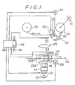
- Fig. 1 is a view showing the overall structure of a printing optical system of an automatic photograph printer to which the present invention is applicable.
- the system includes a light source 10 comprising a halogen lamp having on the reverse side thereof a reflecting mirror consisting of a cold mirror.
- a voltage of about 90 % of the rated voltage is supplied to the light source 10 from a power source, not shown.
- a light adjusting filter 12 On the light-radiation side of the light source 10, a light adjusting filter 12, a light diffusing cylinder 14 having a diffusing plate, and a film feeder 16 for feeding a negative film 70 are disposed in this order.
- the light adjusting filter 12 comprises filter members of three complementary colors, i.e., Y (yellow), M (magenta), and C (cyan). Each filter member has two substantially quarter-circular or fan-shaped filter plates formed on the logarithmic curve, which are combined and laterally disposed as a pair.
- the system has the following arrangement. When light is radiated from the light source 10, the color balance and the quantity of light are adjusted by the adjusting filter 12. Thereafter, the light is transformed by the light diffusing cylinder 14 into evenly diffused light. The diffused light is radiated onto a negative film 70 which is fed by the film feeder 16.
- the film feeder 16 is provided with drive rollers 18 allowing the feeding of the negative film 70 by holding the film 70 therebetween; a notch detector 24 comprising a light emitting element 22A and a light receiving element 22B which are disposed in opposition to each other, with the longitudinal edges of the negative film 70 disposed therebetween; and a splice detector 26 which comprises, similar to the notch detector 24, a light emitting element 26A and a light receiving element 26B that are disposed in opposition to each other, and which are provided to detect splicing tape.
- the drive rollers 18 are rotated by the operation of a pulse motor 20.
- the negative film 70 has notches 74 already formed by a notch puncher on one longitudinal edge at positions corresponding to the frames thereof that have images to be printed.
- the negative film 70 comprises a plurality of negative films linked together by pieces 72 of splicing tape and rolled up.
- a leader portion, not shown, is formed by another piece of splicing tape and is provided at the front end of the negative film leading the plurality of films.
- the notch detector 24 is provided at a position opposing the side edge of the negative film 70 and enabling the detection of the notches 74.
- the splice detector 26 is provided at a position enabling the detection of splicing tape pieces 72 and ensuring that the printing light is not blocked during printing.
- a lens 28 and a black shutter 30 are disposed in this order. Their arrangement is such that, when the shutter 30 is opened, the light transmitted through the negative film 70 forms on printing paper 36 an image corresponding to a frame image.
- the printing paper 36 forms a supply roll 32 and a winding roll 34 thereof, with a part of the paper 36 extending therebetween.
- the printing paper 36 is fed an amount corresponding to the length of a single frame when drive rollers 35 are rotated by a pulse motor 42.
- the winding roll 34 is rotated by another pulse motor 41.
- a dancer mechanism 37 is provided between the drive rollers 35 and the winding roll 34.
- Printing paper which has been exposed passes through a developing process section, not shown, where it is subsequently subjected to developing, fixing, washing, and drying, and, thereafter, it is prepared as prints.
- a printer 38 for printing data such as a dot printer
- a platen 40 is provided so that printing of data can be effected while the printing paper 36 is held between these members 38 and 40.
- the data printer 38 is connected to a control circuit 44 comprising a microcomputer, etc. Also connected to the control circuit 44 is a reader 46 for reading data stored on perforated tape 48.
- the stored data includes splice data A for discriminating one film (i.e., discriminating one order), data B on the kind of the negative, data C indicating the size (e.g., full size or half size) of the image frames, data G indicating the total number of the frames within one film that have images to be printed, and frame data concerned with each of the frame with images and stored in correspondence therewith, such as data D indicating frame numbers, exposure amount correction data E, and data F on the position of the frames with the images to be printed.
- the exposure amount correction data E is determined in a stepped manner, for instance, from D(-4) through N to D (-9).
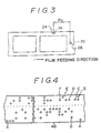
- Data F indicates the position of the frames with the images to be printed in the manner shown in Fig. 5.
- Data F indicates the distance W1 from the splicing tape piece 72 to the notch corresponding to this leading frame with respect to a leading frame having an image to be printed, and indicates the distance W21 from the notch corresponding to the leading frame to the notch corresponding to this subsequent frame with respect to a subsequent frame having an image to be printed, and also indicates the distance W22 from the notch corresponding to the immediately previous frame having an image to be printed to the notch corresponding to this further subsequent frame with respect to a further subsequent frame having an image to be printed.
- Data F on position may be provided as binary digits indicating these distances or binary digits obtained by converting these distances into numbers of pulses supplied to the pulse motor 20.
- the control circuit 44 has a CPU 50, a ROM 52, a RAM 54, an output port 56, an input port 58, and buses connecting these elements including data buses and control buses.
- the output port 56 is connected, through drivers 60, 62, 64, 66 and 68, to the pulse motor 42, the data printer 38, the black shutter 30, the adjusting filter 12, and the pulse motor 20, respectively.
- the notch detector 24, the input terminals of the drivers 60 and 68, the reader 46, and the splice detector 26 are connected to the input port 58.
- the ROM 52 stores therein a program for the control routines described below. The operation of this embodiment will be described hereunder by giving descriptions concerning the program for the control routines.
- Fig. 6 shows an interrupt routine which is inserted at the rising of a pulse signal supplied to the pulse motor 20 for driving the drive rollers 18 of the film feeder 16. Upon the onset of the pulse signal, the number P of pulses is incremented at Step 100. Thereafter, the program returns to the main routine.
- Figs. 7(A) to (C) show the main routine of this embodiment.
- the automatic photograph printer is actuated when the starting switch of the photograph printer is turned on after the printing paper 36 has been set in place, and then the perforated tape 48 and the leading portion connected to the leading negative film have been respectively set in the reader 46 and the film feeder 16.
- initialization is effected with respect to, for instance, a count value q which indicates the number of notches detected.
- a pulse signal is supplied through the driver 68 to the pulse motor 20 to start the rotation of the drive rollers 18, thereby starting the feeding of the negative film 70.
- Step 106 it is determined on the bases of a signal output from the splice detector 26 whether a splicing tape piece 72 has been detected. If a splicing tape piece 72 has been detected, the pulse number P is set to its initial value P0 in Step 108. This is followed by the execution of Step 109 where the reader 46 is driven to load data pertinent to one negative film from the perforated tape 48 onto RAM 54. Thereafter, the data is checked at Step 111. This data checking will be described later in detail.
- the initial value P0 is a pulse number corresponding to the distance between the notch detector 24 and the splice detector 26 (see Fig. 3). In this way, the pulse number P is incremented according to the routine shown in Fig.
- the pulse number P indicates the number of pulses supplied to the pulse motor 20 from the time of the detection of a splicing tape piece. Because the amount by which the film is fed in response to each pulse is known already, it is possible to detect from the pulse number P the amount by which the film has been fed.
- Step 110 is executed where it is determined on the bases of a signal output by the notch detector 24 whether a notch has been detected. If a notch 74 has been detected, the feeding of the negative film is stopped, at Step 112. By this action, the image frame corresponding to the detected notch is positioned in the printing position. At the following step 114, the count value q indicating the number of notches detected is incremented. Then, at Step 116, position data F loaded from the perforated tape 48 onto the RAM 54, frame number data D, and data C which indicates the image frame size are read, together with the pulse number P.
- the frame number of the image frame positioned at the printing position is estimated by calculating, from the read pulse number P and the film feeding amount per pulse, the film feeding amount that corresponds to the read pulse number P. That is, for instance, when the film feeding amount is equal to the distance W1 from the splicing tape piece to the notch of the leading frame, the pertinent frame number is estimated to be "1" shown in Fig. 5. With respect to the subsequent image frames, since the negative film is fed by an amount equaling the frame size multiplied by an integer before the film is stopped, the frame number of a subsequent frame with an image to be printed can be estimated by adding 1 to the integral quotient obtained by dividing by the frame size the feeding amount from the leading frame.
- step 120 it is determined whether the relevant frame number stored in the perforated tape 48 is identical with the frame number thus estimated at Step 118. If these numbers are identical, it is possible to determine that no errors have occurred in the inputting or reading of the data indicating the frame number. Therefore, the program proceeds to 123 where the pulse count valve P is set to 0 so as to enable the detection of the feeding amount using, as the reference, the notch that has just been detected. Thereafter, at Step 124, data such as data B, concerning the kind of the negative and exposure amount correction data E is read. Then, at Step 126, a printing process is performed after the exposure amount, which is calculated by the photograph printer, has been corrected on the basis of the exposure amount correction data and taking into consideration the kind of negative.
- step 1208 while the printing paper which has been subjected to printing at 128 is fed by an amount corresponding to one frame, the data printer 38 is driven, so as to perform a data printing process in which necessary data such as the frame number and the kind of the negative is printed on the reverse surface of the printing paper.
- Step 120 if it is determined, at Step 120, that the frame number stored on the perforated tape 48 and the frame number estimated at Step 118 are not identical, there is a risk than an error might have occurred during the inputting of the frame number or the reading of the data. Therefore, the program proceeds to Step 122 where an alarm or the like is generated, and then gols on to Step 124. Thereafter, the operator stops the automatic photograph printer, confirms the fact that the frame numbers are not identical, and corrects the frame number. At this time, based on the grounds that the estimated frame number is correct, the frame number which is automatically stored in the RAM 54 may be corrected so as to be the same as the estimated frame number.
- Step 130 a determination is made as to whether the printing with respect to the entire negative film has been completed. It completion is determined, the routine is terminated.
- Data checking at Step 111 it is determined whether a certain number of items of data corresponding to one negative film has been correctly input and correctly read.
- data G which are stored on the perforated tape 48 and indicating the number of the frames that are within the one negative film and that have images to be printed, is compared with a count value obtained by counting the items of data of a certain sort which indicates each frame as discriminated from others, for instance, the exposure amount correction data.
- D key data such as the exposure amount correction data
- D key data can be used because it is stored in correspondence with the frames that have images to be printed.
- the read data it is determined whether the read data accords with the codes of data previously registered. By this determination, it is possible to see if there have been any errors in the reading of the data. Still further, since the frame numbers change within one negative film in the direction in which they increase or decrease in the order they have been read or input, the direction in which the read frame numbers change is determined to see if there have been any input errors in the inspection apparatus or any reading errors in the reader. If any abnormality is found after the completion of the above-described checks, an alarm is generated. If necessary, the automatic photograph printer is stopped so that correction can be performed either by the operator or automatically.
- Fig. 8 shows an interrupt routine which is inserted at the onset of a pulse signal for driving the pulse motor 42 connected to the drive rollers 35.
- this interrupt routine is started so that, at Step 140, a count value m indicating the number of pulses is incremented. Thereafter, the program returns to the main routine.
- Figs. 9 (A) and (B) show details of Step 128.
- the count value m is set to 0 at Step 142, and, thereafter, a pulse signal is supplied to the pulse motor 42 so as to start the feeding of the printing paper 36.
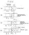
- a predetermined value M is set at a value equal to the number of pulses required to feed the printing paper 36 from the time at which the printing paper feeding has started until a printing paper 36 portion K1 whose exposure to light was completed last time reaches a data printing start position (hereafter the portion K1 will be referred to as the "last exposure portion").
- Step 146 If the count value m is determined to have come above the predetermined value M, at Step 146, it is determined that the printing paper 36 has been fed by an amount required to position the last exposure portion K1 in the position shown in Fig. 10 (B), at which the printing of the latter half of data for the portion K1 is started.
- Step 148 a data printing signal is supplied to the data printer 38, and printing is started in order to print the data which has not yet been provided on the portion K1.
- step 150 it is determined whether the printing with respect to the last exposure portion K1 has been completed, and, if the answer is affirmative, the program proceeds to Step 152.
- the predetermined value L is set at a value equal to the number of pulses required to feed the printing paper 36 from the time of the start of the feeding of the printing paper 36 until a portion K2 which has recently been exposed (the portion K2 will hereafter be referred to as the "recent exposure portion") reaches a position at which its data printing start portion is immediately below the data printer 38. If the count value m is determined to have come above the predetermined value L, at the step 152, it is determined that the data printing start portion is positioned immediately below the data printer 38, as shown in Fig. 10 (C).
- Step 154 is executed in which a data printing signal is output to the data printer 38, and the printing of the first half of the data to be provided on the recent exposure portion K2 is started.
- Step 156 it is determined whether this printing of the first half of the data for the recent exposure portion K2 has been completed. If the completion is determined, Step 158 is executed to determine on the basis of the count value m whether the printing paper 36 has been fed by an amount corresponding to one frame. If the printing paper 36 is determined to have been fed by this amount, Step 160 is executed in which the supply of the pulse signal to the pulse motor 42 is stopped whereby the feeding of the printing paper 36 is terminated. Consequently, the printing paper 36 is positioned in the position shown in Fig.
- the data printer 38 is located at the center of a printing paper 36 portion K1, K2, or the like (i.e., at a position which is one-half of a printing paper portion downstream (in the direction of the feeding of the printing paper 36) from the downstream end of the exposed portion).
- the data printer 38 may be positioned at this time at a position which is one printing paper portion distant from the downstream end of the exposed portion.
- the distance between two adjacent image frames corresponds to the value of full size or half size (i.e., about 38 mm or about 17 mm)
- these values may not be input, and the operation may be performed on the assumption that the data is already provided on the reading side.
- paper tape is used as the storage medium in the foregoing embodiment
- storage medium of other types such as a floppy disk, may be alternatively used.
Landscapes
- Physics & Mathematics (AREA)
- General Physics & Mathematics (AREA)
- Projection-Type Copiers In General (AREA)
Applications Claiming Priority (2)
| Application Number | Priority Date | Filing Date | Title |
|---|---|---|---|
| JP63059738A JPH01232337A (ja) | 1988-03-14 | 1988-03-14 | 写真焼付方法 |
| JP59738/88 | 1988-03-14 |
Publications (3)
| Publication Number | Publication Date |
|---|---|
| EP0333092A2 true EP0333092A2 (de) | 1989-09-20 |
| EP0333092A3 EP0333092A3 (en) | 1990-09-26 |
| EP0333092B1 EP0333092B1 (de) | 1995-06-14 |
Family
ID=13121858
Family Applications (1)
| Application Number | Title | Priority Date | Filing Date |
|---|---|---|---|
| EP89104391A Expired - Lifetime EP0333092B1 (de) | 1988-03-14 | 1989-03-13 | Photographisches Kopierverfahren |
Country Status (4)
| Country | Link |
|---|---|
| US (1) | US4937617A (de) |
| EP (1) | EP0333092B1 (de) |
| JP (1) | JPH01232337A (de) |
| DE (1) | DE68923019T2 (de) |
Cited By (2)
| Publication number | Priority date | Publication date | Assignee | Title |
|---|---|---|---|---|
| DE4140560A1 (de) * | 1990-12-10 | 1992-06-11 | Fuji Photo Film Co Ltd | Automatische abzugsvorrichtung und verfahren zur ueberpruefung der korrespondenz zwischen einzelbild-spezifikationsdaten und dem aktuellen einzelbild, welches in der abzugsposition in der automatischen abzugsvorrichtung angeordnet ist |
| EP0961163A1 (de) * | 1994-03-25 | 1999-12-01 | Noritsu Koki Co., Ltd. | Verfahren zur Steuerung eines Apparats zur Behandlung eines photographischen Filmes |
Families Citing this family (7)
| Publication number | Priority date | Publication date | Assignee | Title |
|---|---|---|---|---|
| US5023656A (en) * | 1989-04-20 | 1991-06-11 | Fuji Photo Film Co., Ltd. | Photographic printing method |
| US5089691A (en) * | 1989-07-11 | 1992-02-18 | Brother Kogyo Kabushiki Kaisha | Image recording apparatus having bar code reader for reading bar code attached to leading end of microcapsule sheet |
| JP2695978B2 (ja) * | 1990-09-14 | 1998-01-14 | 富士写真フイルム株式会社 | 写真処理方法及びシステム |
| US5406350A (en) * | 1993-12-27 | 1995-04-11 | Eastman Kodak Company | Image recording apparatus |
| US5764870A (en) * | 1994-02-28 | 1998-06-09 | Eastman Kodak Company | Method of making an index print |
| US5576794A (en) * | 1994-05-12 | 1996-11-19 | Eastman Kodak Company | Random batch photofinishing |
| US6049392A (en) * | 1996-04-05 | 2000-04-11 | Konica Corporation | Print production system for photographic document |
Family Cites Families (12)
| Publication number | Priority date | Publication date | Assignee | Title |
|---|---|---|---|---|
| US3716299A (en) * | 1971-09-01 | 1973-02-13 | Bell & Howell Co | Frame count cuer for continuous photographic film printer |
| DE2232934A1 (de) * | 1972-07-05 | 1974-01-24 | Suedcolor W Krug Kg | Belichtungsvorrichtung zur herstellung von papierabzuegen von negativfilmen, insbesondere farbfilmen |
| JPS5932778B2 (ja) * | 1974-04-27 | 1984-08-10 | セキエレクトロニクス カブシキガイシヤ | 写真焼付処理方法並びに装置 |
| US4072419A (en) * | 1974-09-26 | 1978-02-07 | Bell & Howell Company | Frame count cuer for photographic film printers |
| US4065661A (en) * | 1975-04-26 | 1977-12-27 | Eastman Kodak Company | Photofinishing apparatus |
| US4291972A (en) * | 1979-03-23 | 1981-09-29 | Pako Corporation | Photographic reprint system with large print quantity verification |
| US4264197A (en) * | 1979-03-23 | 1981-04-28 | Pako Corporation | Photographic reprint system with dual indicia sensor for synchronization recovery |
| US4294537A (en) * | 1979-03-23 | 1981-10-13 | Pako Corporation | Photographic reprint system with information display |
| JPS56128933A (en) * | 1980-03-14 | 1981-10-08 | Fuji Color Service:Kk | Display method for film frame number to print |
| JPS56128932A (en) * | 1980-03-14 | 1981-10-08 | Fuji Color Service:Kk | Display method for film frame number to print |
| JPS6183526A (ja) * | 1984-10-01 | 1986-04-28 | Fuji Photo Film Co Ltd | トリミング焼付装置 |
| JPH0690394B2 (ja) * | 1986-05-20 | 1994-11-14 | 富士写真フイルム株式会社 | 写真焼付方法 |
-
1988
- 1988-03-14 JP JP63059738A patent/JPH01232337A/ja active Pending
-
1989
- 1989-03-13 EP EP89104391A patent/EP0333092B1/de not_active Expired - Lifetime
- 1989-03-13 DE DE68923019T patent/DE68923019T2/de not_active Expired - Fee Related
- 1989-03-13 US US07/322,027 patent/US4937617A/en not_active Expired - Lifetime
Cited By (3)
| Publication number | Priority date | Publication date | Assignee | Title |
|---|---|---|---|---|
| DE4140560A1 (de) * | 1990-12-10 | 1992-06-11 | Fuji Photo Film Co Ltd | Automatische abzugsvorrichtung und verfahren zur ueberpruefung der korrespondenz zwischen einzelbild-spezifikationsdaten und dem aktuellen einzelbild, welches in der abzugsposition in der automatischen abzugsvorrichtung angeordnet ist |
| DE4140560C2 (de) * | 1990-12-10 | 1998-11-12 | Fuji Photo Film Co Ltd | Automatische Abzugsvorrichtung und Verfahren zur Überprüfung der Korrespondenz zwischen Einzelbild-Spezifikationsdaten und dem aktuellen Einzelbild, welches in der Abzugsposition in der automatischen Abzugsvorrichtung angeordnet ist |
| EP0961163A1 (de) * | 1994-03-25 | 1999-12-01 | Noritsu Koki Co., Ltd. | Verfahren zur Steuerung eines Apparats zur Behandlung eines photographischen Filmes |
Also Published As
| Publication number | Publication date |
|---|---|
| DE68923019D1 (de) | 1995-07-20 |
| JPH01232337A (ja) | 1989-09-18 |
| US4937617A (en) | 1990-06-26 |
| EP0333092A3 (en) | 1990-09-26 |
| EP0333092B1 (de) | 1995-06-14 |
| DE68923019T2 (de) | 1995-10-19 |
Similar Documents
| Publication | Publication Date | Title |
|---|---|---|
| EP0293887B1 (de) | Vorrichtung und Verfahren zum photographischen Abdrucken | |
| EP0721149B1 (de) | Verfahren zur Übertragung der Szenenorientierung eines Kamerafilmes zu einem Fotobehandlungsgerät | |
| US4937617A (en) | Photographic printing method | |
| US4806990A (en) | Photographic printing method | |
| US5336873A (en) | Photographic film having frame number bar codes | |
| US5157437A (en) | Apparatus and method for checking coincidence between frame specification data and an actual frame of an auto-printer | |
| EP0829764B1 (de) | Gerät zum Lesen von Aufzeichnungspapierinformation | |
| US5212367A (en) | Method of reading positional information on photographic film | |
| US5179266A (en) | Photographic film and method of identifying frame numbers of photographic film | |
| EP0308984B1 (de) | Photographischer Drucker | |
| EP0352032B1 (de) | Bildaufzeichnungsvorrichtung | |
| EP0339643B1 (de) | Verfahren zum Bestimmen einer Bildnummer | |
| JPH0764214A (ja) | 写真焼付情報印字装置及び写真プリンタ | |
| JPH071371B2 (ja) | 写真焼付装置 | |
| US5262821A (en) | Condition setup/upkeep print | |
| JP2578494B2 (ja) | 写真フィルム及びそのフレームナンバー続取方法 | |
| US4419009A (en) | Data converting method for reordered prints | |
| US5847809A (en) | Photographic processing apparatus | |
| JP2602582B2 (ja) | オートプリンタのコマ番号印字方法 | |
| JPS63311253A (ja) | 仕上り印画検定装置 | |
| JP2704285B2 (ja) | 原画フィルム処理装置 | |
| JPH0685042B2 (ja) | 写真焼付方法 | |
| JP2744124B2 (ja) | 写真作成方法 | |
| JPH01232338A (ja) | 写真焼付装置 | |
| JPS63301951A (ja) | 齣番号印字装置 |
Legal Events
| Date | Code | Title | Description |
|---|---|---|---|
| PUAI | Public reference made under article 153(3) epc to a published international application that has entered the european phase |
Free format text: ORIGINAL CODE: 0009012 |
|
| AK | Designated contracting states |
Kind code of ref document: A2 Designated state(s): DE FR GB |
|
| PUAL | Search report despatched |
Free format text: ORIGINAL CODE: 0009013 |
|
| AK | Designated contracting states |
Kind code of ref document: A3 Designated state(s): DE FR GB |
|
| 17P | Request for examination filed |
Effective date: 19910227 |
|
| 17Q | First examination report despatched |
Effective date: 19921230 |
|
| GRAA | (expected) grant |
Free format text: ORIGINAL CODE: 0009210 |
|
| AK | Designated contracting states |
Kind code of ref document: B1 Designated state(s): DE FR GB |
|
| REF | Corresponds to: |
Ref document number: 68923019 Country of ref document: DE Date of ref document: 19950720 |
|
| ET | Fr: translation filed | ||
| RAP2 | Party data changed (patent owner data changed or rights of a patent transferred) |
Owner name: FUJI PHOTO FILM CO., LTD. |
|
| PLBE | No opposition filed within time limit |
Free format text: ORIGINAL CODE: 0009261 |
|
| STAA | Information on the status of an ep patent application or granted ep patent |
Free format text: STATUS: NO OPPOSITION FILED WITHIN TIME LIMIT |
|
| 26N | No opposition filed | ||
| REG | Reference to a national code |
Ref country code: GB Ref legal event code: IF02 |
|
| PGFP | Annual fee paid to national office [announced via postgrant information from national office to epo] |
Ref country code: FR Payment date: 20040114 Year of fee payment: 16 |
|
| PGFP | Annual fee paid to national office [announced via postgrant information from national office to epo] |
Ref country code: GB Payment date: 20040303 Year of fee payment: 16 |
|
| PGFP | Annual fee paid to national office [announced via postgrant information from national office to epo] |
Ref country code: DE Payment date: 20040430 Year of fee payment: 16 |
|
| PG25 | Lapsed in a contracting state [announced via postgrant information from national office to epo] |
Ref country code: GB Free format text: LAPSE BECAUSE OF NON-PAYMENT OF DUE FEES Effective date: 20050313 |
|
| PG25 | Lapsed in a contracting state [announced via postgrant information from national office to epo] |
Ref country code: DE Free format text: LAPSE BECAUSE OF NON-PAYMENT OF DUE FEES Effective date: 20051001 |
|
| GBPC | Gb: european patent ceased through non-payment of renewal fee |
Effective date: 20050313 |
|
| PG25 | Lapsed in a contracting state [announced via postgrant information from national office to epo] |
Ref country code: FR Free format text: LAPSE BECAUSE OF NON-PAYMENT OF DUE FEES Effective date: 20051130 |
|
| REG | Reference to a national code |
Ref country code: FR Ref legal event code: ST Effective date: 20051130 |