EP0333003B1 - Potentiomètre rotatif - Google Patents
Potentiomètre rotatif Download PDFInfo
- Publication number
- EP0333003B1 EP0333003B1 EP19890104055 EP89104055A EP0333003B1 EP 0333003 B1 EP0333003 B1 EP 0333003B1 EP 19890104055 EP19890104055 EP 19890104055 EP 89104055 A EP89104055 A EP 89104055A EP 0333003 B1 EP0333003 B1 EP 0333003B1
- Authority
- EP
- European Patent Office
- Prior art keywords
- insert
- rotary potentiometer
- rotor
- resistance track
- potentiometer according
- Prior art date
- Legal status (The legal status is an assumption and is not a legal conclusion. Google has not performed a legal analysis and makes no representation as to the accuracy of the status listed.)
- Expired - Lifetime
Links
- 238000010079 rubber tapping Methods 0.000 claims description 11
- 239000004020 conductor Substances 0.000 description 8
- 238000005452 bending Methods 0.000 description 2
- 230000037431 insertion Effects 0.000 description 2
- 238000003780 insertion Methods 0.000 description 2
- 230000004308 accommodation Effects 0.000 description 1
- 239000000853 adhesive Substances 0.000 description 1
- 230000001070 adhesive effect Effects 0.000 description 1
- 230000000694 effects Effects 0.000 description 1
- 239000011888 foil Substances 0.000 description 1
- 238000007789 sealing Methods 0.000 description 1
- 238000004804 winding Methods 0.000 description 1
Images


Classifications
-
- H—ELECTRICITY
- H01—ELECTRIC ELEMENTS
- H01C—RESISTORS
- H01C10/00—Adjustable resistors
- H01C10/30—Adjustable resistors the contact sliding along resistive element
- H01C10/32—Adjustable resistors the contact sliding along resistive element the contact moving in an arcuate path
Definitions
- the invention relates to a rotary potentiometer, in which a resistance track is arranged on the inside of a cylindrical wall of a housing, in which a rotor is rotatably mounted about its cylinder axis, to which a wiper which is in contact with the resistance track is fastened.
- DE-AS 1 790 163 describes a small potentiometer, in the housing of which can be closed with a cover, a grinder spindle and a resistance winding are arranged axially parallel. This arrangement cannot be used for a rotary potentiometer of the type mentioned at the outset.
- the object of the invention is to propose a rotary potentiometer of the type mentioned, in which an axial insertion of the grinder into the housing is avoided during assembly.
- the above object is achieved with a rotary potentiometer of the type mentioned at the outset in that an opening is formed on the circumference of the wall through which the rotor can be inserted in the radial direction to the cylinder axis and which can be closed with an insert.
- the insert itself can carry functional elements of the rotary potentiometer. It is only attached after the rotor has been inserted.
- the resistance track is applied to a carrier film which is inserted through the opening in the housing. This makes it easier to arrange the resistance track in the correct position.
- the rotor is preferably rotatably mounted on the insert itself, the rotor axis of rotation lying in the cylinder axis when the insert is pushed into the opening. This makes assembly even easier. Because the rotor with the grinder and its electrical connection with the corresponding connection in use, e.g. by means of a spiral spring, can then be mounted on the insert outside the housing. After inserting the insert into the housing, the rotor is in the correct position and the insert closes the opening.
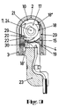
- a rotary potentiometer has a housing (1) which forms a cylindrical wall (2) extending over 180 ° and two wall legs (3, 4) which extend tangentially, as well as an upper (5) and a lower wall part (6).
- the cylinder axis of the wall (2) is designated (7).
- Edges (3 ', 4', 5 ', 6') of the wall legs (3, 4) or the wall parts (5, 6) enclose an opening (8).
- a flexible film (9) which carries a resistance track (10) is inserted into the housing (1). This runs partially cylindrical like the wall (2). It extends over a maximum of 180 °.
- the film (9) is shown unwound in Figure 2. It has conductor tracks (11, 12) which are connected to individual electrodes (14) via diodes (13). The individual electrodes (14) lie on the four edges of the resistance track (10).
- the conductor tracks (11, 12) can be connected to a flexible extension (9 ') of the film (9).
- the resistance track (10) can be laminated onto the film (9).
- the film can be glued into the housing (1). It is also possible to apply the resistance track (10) directly to the wall (2).
- the diodes (13) can also be applied to the film (9) after it has been inserted by means of a conductive adhesive. Your determination is then not burdened by mechanical stresses in the bending of the film (9). If the film (9) to be used is already equipped with diodes (13), its arrangement is advantageous on the parts of the film (9) which, after being inserted, rest on flat wall legs (3, 4); mechanical stresses due to the bending of the foil (9) are also avoided on the diodes (13).
- An insert (15) is provided, the cross section of which corresponds to the free cross section of the opening (8).
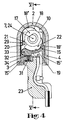
- a bearing journal (16) for a rotor (17) is formed on the insert (15) and carries a grinder (18).
- a partially cylindrical tapping surface (19) is formed on the insert (15), the size and radius of which corresponds to the resistance track (10).
- a stop web (20) is provided, to which stop lugs (21, 22) of the rotor (17) are assigned. These serve to limit the rotary movement of the rotor (17) to the extent of the resistance track (10) or the tapping surface (19).
- a plug (23) can be plugged in, which electrically connects the conductor tracks (11, 12) and the tapping surface (19).
- the rotor (17) is not only rotatable on the journal (16) about the axis of rotation (24) but also displaceable in its axial direction. It has a receptacle (25) for a drive rod (26).
- the receptacle (25) is provided with tangential slots (27) which make the receptacle (25) bendable in order to compensate for an axial offset between the drive rod (26) and the rotor (17).
- the drive rod (26) and the receptacle (25) are designed such that the drive rod (26) can be inserted into the receptacle (25) in a rotationally fixed and axially fixed manner.
- a bushing (28) for the drive rod (26) is formed on the wall part (5) of the housing (1).
- the assembly of the rotary potentiometer described is done as follows: After inserting the film (9) into the housing (1), the rotor (17) is placed on the bearing journal (16) so that the stop bar (20) stands between the two stop lugs (21, 22) and one end ( 18 ') of the grinder (18) on the tapping surface (19). The insert (15) is then inserted into the opening (8) and inserted between the wall legs (3, 4) and the wall parts (5, 6) into the housing (1), surfaces (15 ') of the insert (15) provide the appropriate guidance. In the inserted position, the insert (15) can be locked to the housing (1) by means of locking means (not shown). In this position, the cylinder axis (7) and the axis of rotation (24) are aligned. The end (18 '') of the grinder (18) resiliently rests on the resistance track (10).
- the drive rod (26) is then inserted through the bushing (28) into the receptacle (25) of the rotor (17) and the plug (23) is connected. If the drive rod (26) is now turned in the direction of arrow (D) or moved in the direction of arrow (H), then the grinder (18) picks up a corresponding voltage on the resistance track (10), which voltage is applied via the conductor tracks (11, 12), e.g. clocked with changing polarity, is brought up to the resistance track (10).
- pins (29) are provided on the inside of the wall legs (3, 4), to which corresponding free cuts (37) of the film (9) are assigned. This allows the film (9), which also extends along the wall legs (3, 4), Arrange in the correct position in the housing (1) in a simple manner. Due to its inherent elasticity, the film (9) is stretched flush against the cylindrical wall (2) by the pins (29).
- Contact springs (30) are provided on the insert (15) for contacting the conductor tracks (11, 12) (cf. FIGS. 3, 5).
- a contact spring (31) is further arranged on the insert (15), which contacts a conductor track (32) connected to the tapping surface (19) (cf. FIG. 4).
- the conductor track (32) is guided around a curve (33) of the insert (15). It ends in a recess (34). There the contact spring (31) lies against it.
- the contact springs (30, 31) are contacted by inserting the plug (23).
- a bellows (35) is provided to improve the sealing effect in the area of the passage of the drive rod (26).
- the bellows (35) is held at one end on the housing (1). Its other end abuts the rotor (17).
- FIG. 5 also shows a latching tongue (36) with which the drive rod (26) can be fixed axially to the rotor (17).
- the tapping surface (19) can also be arranged in the axial direction next to the resistance track.
Landscapes
- Engineering & Computer Science (AREA)
- Microelectronics & Electronic Packaging (AREA)
- Adjustable Resistors (AREA)
Claims (10)
- Potentiomètre rotatif comprenant une piste résistive (10) disposée à l'intérieur sur une paroi cylindrique (2) d'un boîtier (1), dans lequel un rotor (17) est monté rotatif autour de l'axe de cylindre (7) de cette paroi, rotor auquel est fixé un curseur (18) appliqué contre la piste résistive (10), caractérisé en ce qu'une ouverture (8) est formée à la périphérie de la paroi (2), à travers de laquelle le rotor (17) peut être introduit en direction radiale par rapport à l'axe de cylindre (7) et qui est obturable par une pièce encastrée ou insert (15).
- Potentiomètre rotatif selon la revendication 1, caractérisé en ce que la piste résistive (10) est appliquée sur une feuille (9) qui est mise en place dans le boîtier (1) à travers l'ouverture (8).
- Potentiomètre rotatif selon la revendication 1 ou 2, caractérisé en ce que le rotor (17) est monté rotatif sur l'insert (15), l'axe de rotation (24) du rotor étant situé sur l'axe de cylindre (7) lorsque l'insert (15) a été mis en place dans l'ouverture (8).
- Potentiomètre rotatif selon une des revendications précédentes, caractérisé en ce que la piste résistive (10) s'étend tout au plus sur 180° et l'insert (15) est pourvu d'une surface de prise (19) ayant une forme cylindrique correspondant à celle de la piste résistive (10) et contre laquelle est appliqué le curseur (18).
- Potentiomètre rotatif selon une des revendications précédentes, caractérisé en ce que le boîtier (1) comporte des portions de paroi (3, 4) qui prolongent tangentiellement la paroi cylindrique (2) et délimitent l'ouverture (8).
- Potentiomètre rotatif selon la revendication 5, caractérisé en ce que la feuille (9) porte, en plus de la piste résistive (10), des composants électriques (13) dont la disposition sur la feuille (9) est coordonnée aux portions de paroi (3, 4) à surface plane.
- Potentiomètre rotatif selon une des revendications précédentes, caractérisé en ce qu'une nervure de butée (20) est prévue sur l'insert (15) pour limiter le mouvement de rotation du rotor (17).
- Potentiomètre rotatif selon une des revendications précédentes, caractérisé en ce que le rotor (17) est monté mobile longitudinalement, dans le sens de l'axe de rotation (24), sur l'insert (15).
- Potentiomètre rotatif selon une des revendications précédentes, caractérisé en ce que le rotor (17) est pourvu d'une réception (25) pour une tige de commande (26) qui dépasse en haut du boîtier (1).
- Potentiomètre rotatif selon une des revendications précédentes, caractérisé en ce qu'une fiche de connecteur (23) est prévue sur l'insert (15) pour le raccordement électrique de la piste résistive (10) et de la surface de prise (19).
Applications Claiming Priority (2)
| Application Number | Priority Date | Filing Date | Title |
|---|---|---|---|
| DE19883808583 DE3808583C1 (fr) | 1988-03-15 | 1988-03-15 | |
| DE3808583 | 1988-03-15 |
Publications (3)
| Publication Number | Publication Date |
|---|---|
| EP0333003A2 EP0333003A2 (fr) | 1989-09-20 |
| EP0333003A3 EP0333003A3 (en) | 1990-04-18 |
| EP0333003B1 true EP0333003B1 (fr) | 1993-10-20 |
Family
ID=6349755
Family Applications (1)
| Application Number | Title | Priority Date | Filing Date |
|---|---|---|---|
| EP19890104055 Expired - Lifetime EP0333003B1 (fr) | 1988-03-15 | 1989-03-08 | Potentiomètre rotatif |
Country Status (2)
| Country | Link |
|---|---|
| EP (1) | EP0333003B1 (fr) |
| DE (1) | DE3808583C1 (fr) |
Family Cites Families (4)
| Publication number | Priority date | Publication date | Assignee | Title |
|---|---|---|---|---|
| DE1790163C3 (de) * | 1968-09-20 | 1973-12-06 | Dale Electronics, Inc., Columbus, Nebr. (V.St.A.) | Kleinpotentiometer mit einem länglichen, durch einen Gehausedeckel verschließbaren quaderförmig«] Gehäuse |
| US4355293A (en) * | 1979-10-22 | 1982-10-19 | The Bendix Corporation | Electrical resistance apparatus having integral shorting protection |
| FR2560428B1 (fr) * | 1984-02-28 | 1987-02-27 | Renix Electronique Sa | Potentiometre rotatif notamment de mesure de position angulaire |
| DE3631058A1 (de) * | 1986-09-12 | 1988-03-24 | Preh Elektro Feinmechanik | Verfahren zur herstellung von leit- und/oder widerstandsbahnen an einem substrat und nach diesem verfahren hergestelltes potentiometer |
-
1988
- 1988-03-15 DE DE19883808583 patent/DE3808583C1/de not_active Expired
-
1989
- 1989-03-08 EP EP19890104055 patent/EP0333003B1/fr not_active Expired - Lifetime
Also Published As
| Publication number | Publication date |
|---|---|
| DE3808583C1 (fr) | 1989-05-11 |
| EP0333003A2 (fr) | 1989-09-20 |
| EP0333003A3 (en) | 1990-04-18 |
Similar Documents
| Publication | Publication Date | Title |
|---|---|---|
| DE2749028C2 (de) | Hochspannungssteckverbindung | |
| EP0920723B1 (fr) | Unite d'entrainement electrique | |
| DE60008058T2 (de) | Drehverbinder | |
| DE69501873T2 (de) | Wasserdichte elektrische Verbindungsvorrichtung | |
| DE2912413C2 (fr) | ||
| EP1257438B1 (fr) | Dispositif pour transmettre un courant electrique entre deux elements a torsion mutuelle d'un mecanisme de direction pour automobiles | |
| DE1961846B2 (de) | Drehzahlgeber zur Bestimmung der Drehzahl oder Drehzahländerung von Fahrzeugrädern, insbesondere für Bremsschlupfregelanlagen von Kraftfahrzeugen | |
| DE4028892A1 (de) | Antriebsvorrichtung, insbesondere fuer scheibenwischer an kraftfahrzeugen | |
| EP1096649B1 (fr) | Outillage de sondage | |
| EP0387585A1 (fr) | Spirale de câble plat | |
| EP0333003B1 (fr) | Potentiomètre rotatif | |
| DE2155457B2 (de) | Elektrowerkzeug mit einem axial verschiebbaren Stator | |
| DE2742749A1 (de) | Endschalter | |
| DE2548131A1 (de) | Kabelhaspel | |
| DE112006003971T5 (de) | Rotationsanschlussmechanismus | |
| DE1440751B2 (de) | Wendelpotentiometer | |
| EP0344628B1 (fr) | Douille antidéflagrante pour 2 broches-tubes fluorescents | |
| DE19547959A1 (de) | Vorrichtung zum elektrischen Verbinden von Teilen an dem Lenkrad und der Lenksäule eines Kraftfahrzeuges | |
| DE1763883C3 (de) | Bürstenhalter | |
| DE102019120437B4 (de) | Königszapfenanordnung | |
| DE3727199C1 (en) | Coaxial cable plug connector | |
| DE2805509A1 (de) | Rohrverbinder | |
| DE10162127A1 (de) | Elektrischer Verbinder zwischen zwei Endstellen | |
| DE2607075A1 (de) | Drehbare elektrische leitungskupplung sowie hiermit bestueckte kabelaufwickelvorrichtung | |
| DE8812072U1 (de) | Funkentstörter Kommutatormotor, insbesondere Kraftfahrzeug-Bordmotor |
Legal Events
| Date | Code | Title | Description |
|---|---|---|---|
| PUAI | Public reference made under article 153(3) epc to a published international application that has entered the european phase |
Free format text: ORIGINAL CODE: 0009012 |
|
| AK | Designated contracting states |
Kind code of ref document: A2 Designated state(s): FR GB IT |
|
| PUAL | Search report despatched |
Free format text: ORIGINAL CODE: 0009013 |
|
| AK | Designated contracting states |
Kind code of ref document: A3 Designated state(s): FR GB IT |
|
| 17P | Request for examination filed |
Effective date: 19900911 |
|
| 17Q | First examination report despatched |
Effective date: 19930326 |
|
| GRAA | (expected) grant |
Free format text: ORIGINAL CODE: 0009210 |
|
| AK | Designated contracting states |
Kind code of ref document: B1 Designated state(s): FR GB IT |
|
| ET | Fr: translation filed | ||
| GBT | Gb: translation of ep patent filed (gb section 77(6)(a)/1977) |
Effective date: 19931102 |
|
| ITF | It: translation for a ep patent filed | ||
| PLBE | No opposition filed within time limit |
Free format text: ORIGINAL CODE: 0009261 |
|
| STAA | Information on the status of an ep patent application or granted ep patent |
Free format text: STATUS: NO OPPOSITION FILED WITHIN TIME LIMIT |
|
| 26N | No opposition filed | ||
| PGFP | Annual fee paid to national office [announced via postgrant information from national office to epo] |
Ref country code: GB Payment date: 19970213 Year of fee payment: 9 |
|
| PGFP | Annual fee paid to national office [announced via postgrant information from national office to epo] |
Ref country code: FR Payment date: 19970214 Year of fee payment: 9 |
|
| PG25 | Lapsed in a contracting state [announced via postgrant information from national office to epo] |
Ref country code: GB Free format text: LAPSE BECAUSE OF NON-PAYMENT OF DUE FEES Effective date: 19980308 |
|
| PG25 | Lapsed in a contracting state [announced via postgrant information from national office to epo] |
Ref country code: FR Free format text: THE PATENT HAS BEEN ANNULLED BY A DECISION OF A NATIONAL AUTHORITY Effective date: 19980331 |
|
| GBPC | Gb: european patent ceased through non-payment of renewal fee |
Effective date: 19980308 |
|
| REG | Reference to a national code |
Ref country code: FR Ref legal event code: ST |
|
| PG25 | Lapsed in a contracting state [announced via postgrant information from national office to epo] |
Ref country code: IT Free format text: LAPSE BECAUSE OF NON-PAYMENT OF DUE FEES;WARNING: LAPSES OF ITALIAN PATENTS WITH EFFECTIVE DATE BEFORE 2007 MAY HAVE OCCURRED AT ANY TIME BEFORE 2007. THE CORRECT EFFECTIVE DATE MAY BE DIFFERENT FROM THE ONE RECORDED. Effective date: 20050308 |