EP0332746A2 - Ausleger für Trag- oder Aufhängevorrichtungen für Kabel, Rohre und dergleiche - Google Patents
Ausleger für Trag- oder Aufhängevorrichtungen für Kabel, Rohre und dergleiche Download PDFInfo
- Publication number
- EP0332746A2 EP0332746A2 EP88118552A EP88118552A EP0332746A2 EP 0332746 A2 EP0332746 A2 EP 0332746A2 EP 88118552 A EP88118552 A EP 88118552A EP 88118552 A EP88118552 A EP 88118552A EP 0332746 A2 EP0332746 A2 EP 0332746A2
- Authority
- EP
- European Patent Office
- Prior art keywords
- boom
- stem
- flange
- connecting piece
- web
- Prior art date
- Legal status (The legal status is an assumption and is not a legal conclusion. Google has not performed a legal analysis and makes no representation as to the accuracy of the status listed.)
- Granted
Links
Images


Classifications
-
- H—ELECTRICITY
- H02—GENERATION; CONVERSION OR DISTRIBUTION OF ELECTRIC POWER
- H02G—INSTALLATION OF ELECTRIC CABLES OR LINES, OR OF COMBINED OPTICAL AND ELECTRIC CABLES OR LINES
- H02G3/00—Installations of electric cables or lines or protective tubing therefor in or on buildings, equivalent structures or vehicles
- H02G3/26—Installations of cables, lines, or separate protective tubing therefor directly on or in walls, ceilings, or floors
- H02G3/263—Installation, e.g. suspension, of conduit channels or other supports
-
- A—HUMAN NECESSITIES
- A47—FURNITURE; DOMESTIC ARTICLES OR APPLIANCES; COFFEE MILLS; SPICE MILLS; SUCTION CLEANERS IN GENERAL
- A47B—TABLES; DESKS; OFFICE FURNITURE; CABINETS; DRAWERS; GENERAL DETAILS OF FURNITURE
- A47B57/00—Cabinets, racks or shelf units, characterised by features for adjusting shelves or partitions
- A47B57/30—Cabinets, racks or shelf units, characterised by features for adjusting shelves or partitions with means for adjusting the height of detachable shelf supports
- A47B57/44—Cabinets, racks or shelf units, characterised by features for adjusting shelves or partitions with means for adjusting the height of detachable shelf supports consisting of screwbolts as connecting members
- A47B57/46—Cabinets, racks or shelf units, characterised by features for adjusting shelves or partitions with means for adjusting the height of detachable shelf supports consisting of screwbolts as connecting members the shelf supports being cantilever brackets
-
- F—MECHANICAL ENGINEERING; LIGHTING; HEATING; WEAPONS; BLASTING
- F16—ENGINEERING ELEMENTS AND UNITS; GENERAL MEASURES FOR PRODUCING AND MAINTAINING EFFECTIVE FUNCTIONING OF MACHINES OR INSTALLATIONS; THERMAL INSULATION IN GENERAL
- F16L—PIPES; JOINTS OR FITTINGS FOR PIPES; SUPPORTS FOR PIPES, CABLES OR PROTECTIVE TUBING; MEANS FOR THERMAL INSULATION IN GENERAL
- F16L3/00—Supports for pipes, cables or protective tubing, e.g. hangers, holders, clamps, cleats, clips, brackets
- F16L3/24—Supports for pipes, cables or protective tubing, e.g. hangers, holders, clamps, cleats, clips, brackets with special member for attachment to profiled girders
- F16L3/243—Supports for pipes, cables or protective tubing, e.g. hangers, holders, clamps, cleats, clips, brackets with special member for attachment to profiled girders the special member being inserted in the profiled girder
Definitions
- the invention relates to a carrying or hanging device for cables, pipes and the like. with the features of the preamble of claim 1.
- brackets In such support or suspension devices known from practice, there is a cohesive, mostly welded connection between the connecting piece and the boom, which is capable of introducing both the transverse forces and the bending moments from the boom into the arm.
- This very robust and, in itself, simple, automatically established connection between the connecting piece and the bracket cannot be changed subsequently.
- brackets There are also different stick geometries to which the brackets are to be attached. The range of bracket and connector combinations to be kept in stock is correspondingly large if both are permanently connected by the manufacturer.
- the corrosion protection for example in the form of galvanizing, can be applied only at the very end, since galvanized parts are welded on the one hand toxic fumes are generated and on the other hand the zinc layer burns away in the vicinity of the weld so that it is otherwise unprotected. It is therefore impossible to manufacture the parts from semi-finished products (coil) that have already been galvanized.
- the connecting piece and the bracket in one piece.
- the wall thickness of the material used must depend on the part on which the greatest forces occur, namely the connecting piece.
- the boom is then usually very oversized, but this does not contribute to strength, but only increases the material costs.
- the connecting piece consists of an approximately Z-shaped bent sheet metal part in order to bring the flanges of the bracket into the region of the flange of the stick when the connecting piece is attached to the web of the stick.
- the bolt-shaped connecting element is a threaded screw with a screwed-on nut, which does not even have to be tightened in order to fulfill the function. Slight hand tightening is all it takes to transfer the shear forces that occur.
- the connecting piece has a tab which lies between the abutment edge of the boom and the flange of the stick.
- the force emanating from the abutment edge of the boom is thus distributed over a larger area on the stick.
- this embodiment of the connecting piece permits the use of thin-walled stems in which the necessary bending stiffness is obtained by multiple bending in the longitudinal direction. Although this saves weight, it makes the handles sensitive to lateral denting when excessive forces occur on surfaces that are too small, such as the edges of outrigger arms.
- FIGS. 2 and 3 show a carrying and hanging device 1 for cables, pipes and the like, which are either arranged directly on the carrying device 1 or in platforms and channels which are held on the carrying device 1.
- 1 is fastened to a structure of a building in the form of a ceiling 2 and contains a vertically extending handle 3, on which a plurality of brackets 4 are supported so as to protrude in opposite directions on both sides.
- An embodiment of the boom 4 is shown in FIGS. 2 and 3 in detail.
- the back part 5 tapers, starting from one end 8 to the other opposite end 9, such that the upper and lower flanges 6 and 7 converge towards one another in the direction of the end 9.
- a cranked gusset plate 11 is provided, which forms two mutually parallel holding flanges 12 and 13, which are formed by an intermediate piece 14 running at right angles to the two holding flanges 12 and 13 are integrally connected.
- the depth of the intermediate piece 14 depends, as can be seen from the description below, on the shape of the handle 3.
- the holding flange 13 forms on its outer side 15 facing the arm 4 a flat contact surface for the inner surface of the back part 5 located between the two flanges 6 and 7.
- the height of the holding flange 13 corresponds essentially to the distance that the two flanges 6 and 7 of the Boom 4 at the end 8, which faces the arm 3 in the assembled state.
- a bore 16 is contained in the back part 5 in the vicinity of the upper flange 6, which bore is aligned with a corresponding bore 17 in the holding flange 13.
- the head of the screw 18 is located on the outside of the arm 4 visible in FIG. 2, while the nut 19 rests on the surface of the holding flange 13 opposite the contact surface 15.
- the screw 18 acts as a hinge or fulcrum and is only subjected to shear stress.
- the torques that occur when the boom 4 is loaded are introduced as lateral forces into the arm 3 via an abutment edge 21.
- the abutment edge 21 is located at the end 8 of the boom 4 facing the arm 3 and is formed by the lower, oblique flange 9.
- the distance that the bore 16 has from the rear edge 8 is therefore also dimensioned such that when the abutment edge 21 abuts the stem 3, the upper flange 6 has the desired horizontal course, that is to say extends at right angles to the stem 3 .
- the other holding flange 12 is used to fasten the connecting piece to the stem 3, the cross section of which results from FIG. 3.
- the stem 3 is profiled continuously over its entire length in a Z-shape and contains a web 22 which is continuous over the longitudinal direction, on the edges of which in the longitudinal direction two stem flanges 23 and 24 are integrally formed extending at right angles to the web 22.
- the two stem flanges 23 and 24 extend, in relation to the plane defined by the web 22, in opposite directions and have the same height in relation to the web 22.
- the height of the intermediate piece 14 of the connecting piece 11 is adapted to the height of these two flanges 23 and 24, such that in the assembled state the abutment edge 21, which extends at right angles to the longitudinal extension of the boom 4, comes to rest in front of one of the two stem flanges 23 and 24.
- the stem 3 also contains in its web 22 a plurality of equidistantly distributed holes 25 which are arranged along the center line of the web and which serve to receive a fastening screw 26.
- a gusset plate 11 is selected after the attachment of the arm 3 to the building structure 2, which is capable of introducing the force occurring on the arm 4 into the arm 3.
- the selected gusset plate 11 is fastened with its holding flange 13 to the bracket 4, in such a way that the holding flange 13 comes to rest on the back part 5 between the two flanges 6 and 7.
- the threaded screw 18 is inserted through the mutually aligned bores 16 and 17 and the nut 19 is screwed onto the threaded bolt 18. This will between receive the gusset plate 11 and the bracket 4 a positive connection, which is initially not yet able to transmit a torque.
- the abutment edge 21 is, as can be seen from the description, below the screw bolt 18, so that when the boom 4 is loaded from above by a force which tends to fold the boom 4 down, a corresponding pressure force from the abutment 21 is transferred to the stem flange 24.
- the boom 4 attached to the arm 3 is thus capable of introducing both lateral forces and torques into the arm 3.
- connector 11 is advantageous. It allows namely that of the Distribute abutment edge pressure applied to a larger area of the stem flanges 23 and 24. Insofar as components and elements that have already been described previously occur in this context, they are provided with the same reference symbols and are not explained again.
- a tab 28 below the holding flange 13 which is formed by U-shaped bending of a corresponding extension on the intermediate piece 14 and runs parallel and at a distance from the outside of the intermediate piece 14 adjacent to the holding flange 13 .
- the distance that the tab 28 has from the outside, ie the side of the intermediate piece 14 adjoining the holding flange 13, corresponds to the thickness of the stem flange 24 including the thickness of the folded-in area 29.
- the position of the tab 28 in the vertical direction is vertical adapted to the abutment edge 21 in such a way that the surface 31 of the tab 28 pointing away from the handle 3 can interact with the abutment edge 21. According to the resulting displacement of the abutment edge 21, the bore 17 in the holding flange 13 has also moved away from the intermediate piece 14.
- FIG. 6 The assembly of the boom 4 with the aid of the connecting piece 11 according to FIGS. 4 and 5 is shown in FIG. 6. 3, the connecting piece 11 is placed around the edge formed between the web 22 and the stem flange 24 and 23 on the outside, in FIG. 6 the holding flange 12 and the intermediate piece 14 are located on the stem 3 in the throat area that arises between the web 22 and the stem flange 24; the distance between the hole 27 and the intermediate piece 14 is selected such that the fastening screw 26 can be used again.
- This type of attachment has the advantage that the forces are introduced directly into the stem flange 23, 24 and the screw 26 is less stressed.
- the tab 28 engages around the stem flange 24 together with the intermediate piece 14 approximately in a fork shape from the side. Since the height of the tab 28 corresponds to the position of the abutment edge 21, the bracket attached to the connecting piece 11 is supported with its abutment edge 21 on the outside 31 of the tab 28. This creates a large-area load on the stem flange 24, which cannot be pressed in even with a small wall thickness. The load capacity is improved accordingly.
- beads 32, 33 can also be provided, which extend beyond the bending edges on which the holding flanges 12 and 13 are connected to the intermediate piece 14.
- the direction in which the beads 32, 33 are raised depends on whether an assembly type according to FIG. 3 or 6 is possible.
- the type of connecting piece 11 and the support 4 used can be freely selected at the construction site and can be easily adapted to the geometry of the stem 3 in this way.
Landscapes
- Engineering & Computer Science (AREA)
- General Engineering & Computer Science (AREA)
- Architecture (AREA)
- Civil Engineering (AREA)
- Structural Engineering (AREA)
- Mechanical Engineering (AREA)
- Supports For Pipes And Cables (AREA)
- Joining Of Building Structures In Genera (AREA)
- Clamps And Clips (AREA)
- Jib Cranes (AREA)
Abstract
Description
- Die Erfindung betrifft eine Trag- oder Aufhängevorrichtung für Kabel, Rohre u.dgl. mit den Merkmalen des Oberbegriffs des Anspruches 1.
- Bei derartigen aus der Praxis bekannten Trag- oder Aufhängevorrichtungen besteht zwischen dem Verbindungsstück und dem Ausleger eine stoffschlüssige, meistens Schweißverbindung, die in der Lage ist, sowohl die Querkräfte als auch die Biegemomente vom Ausleger in den Stiel einzuleiten. Diese sehr robuste und an sich einfache automatisch herzustellende Verbindung zwischen dem Verbindungsstück und dem Ausleger ist nachträglich nicht mehr änderbar. Hieraus resultiert eine große Lagerhaltung, da die Abmessungen der Ausleger an das Gewicht des zu verlegenden Installationsmaterials und an die Menge angepaßt sein müssen, andererseits weit auskragende Ausleger nicht notwendigerweise auch hohe Lasten zu tragen haben. Außerdem gibt es unterschiedliche Stielgeometrien, an denen die Ausleger zu befestigen sind. Entsprechend groß ist die Vielfalt der lagermäßig vorzuhaltenden Kombinationen aus Ausleger und Verbindungsstück, wenn beide herstellerseitig unlösbar miteinander verbunden sind.
- Außerdem kann bei einer Schweißverbindung zwischen den beiden genannten Teilen der Korrosionsschutz beispielsweise in Gestalt einer Verzinkung erst ganz zum Schluß aufgebracht werden, da beim Schweißen verzinkter Teile einerseits giftige Dämpfe entstehen und andererseits die Zinkschicht in der Umgebung der Schweißstelle wegbrennt, so daß diese sonst ungeschützt ist. Es ist deswegen ausgeschlossen, die Teile aus bereits verzinkten Halbfabrikaten (Coil) zu fertigen.
- Schließlich ist es aus der Praxis noch bekannt, das Verbindungsstück und den Ausleger einstückig herzustellen. In diesem Fall muß die Wandstärke des verwendeten Materials sich nach demjenigen Teil richten, an dem die größten Kräfte auftreten, nämlich dem Verbindungsstück. Der Ausleger ist dann üblicherweise stark überdimensioniert, was aber nichts zur Festigkeit beiträgt, sondern nur die Materialkosten erhöht.
- Ausgehend hiervon ist es Aufgabe der Erfindung, eine Tragkonstruktion zu schaffen, die eine flexible Paarung zwischen dem Verbindungsstück und dem Ausleger gestattet, wobei die Art der Befestigung der beiden Teile aneinander sehr einfach sein soll.
- Diese Aufgabe wird erfindungsgemäß durch die Vorrichtung mit den Merkmalen des Anspruches 1 gelöst.
- Bei dieser neuen Art der Befestigung des Auslegers an dem Verbindungsstück braucht bei der Montage nur ein einziges Element eingesetzt zu werden, um den Ausleger hinsichtlich aller wesentlichen an ihm angreifenden Kräfte zu halten. Das Kipp- oder Biegemoment wird über das Verbindungselement als Querkraft übertragen und über den unteren Flansch des Auslegers in den Stiel eingeleitet. Das Verbindungsstück selbst braucht hierbei kein Biegemoment zu übertragen, da der Ausleger hinsichtlich dieser Kräfte unmittelbar mit dem Stiel zusammenwirkt. Durch Wahl des Abstandes der beiden Flansche an dem Ausleger läßt sich außerdem die Größe der Druckkraft, die an der Widerlagerkante auftritt, auf einfache Weise steuern, um die Flächenbelastungen am Stiel oder am Ausleger klein zu halten. Es lassen sich damit auch Teile miteinander verbinden, die aus nicht verschweißbaren Materialien und/oder Beschichtungen bestehen.
- In einer besonders einfachen Ausführungsform besteht das Verbindungsstück aus einem etwa Z-förmig abgekröpften Blechformteil, um die Flansche des Auslegers bei an dem Steg des Stiels angebrachten Verbindungsstück in den Bereich des Flansches des Stiels zu bringen.
- Das bolzenförmige Verbindungselement ist im einfachsten Falle eine Gewindeschraube mit aufgeschraubter Mutter, die, um die Funktion zu erfüllen, noch nicht einmal fest angezogen zu werden braucht. Leichtes Anziehen von Hand genügt völlig, um die auftretenden Scherkräfte zu übertragen.
- Wenn besonders hohe Kräfte übertragen werden sollen, ohne den Korrosionsschutz am Stiel zu durchschneiden, ist es zweckmäßig, wenn das Verbindungsstück eine Lasche aufweist, die zwischen der Widerlagerkante des Auslegers und dem Flansch des Stieles liegt. Die von der Widerlagerkante des Auslegers ausgehende Kraft wird damit auf eine größere Fläche am Stiel verteilt. Insbesondere gestattet diese Ausführungsform des Verbindungsstücks die Verwendung von dünnwandigen Stielen, bei denen die notwendige Biegesteifigkeit durch mehrfaches Umbiegen in Längsrichtung erhalten wird. Dies spart zwar Gewicht, macht die Stiele jedoch empfindlich gegen seitliches Einbeulen beim Auftreten von zu großen Kräften auf zu kleinen Flächen, wie sie die Kanten von Auslegern darstellen.
- In der Zeichnung sind Ausführungsbeispiele des Gegenstandes der Erfindung dargestellt. Es zeigen:
- Fig. 1 eine an einer Decke eines Gebäudes befestigte Tragvorrichtung gemäß der Erfindung in einer Seitenansicht,
- Fig. 2 den Ausleger und das Verbindungsstück der Tragvorrichtung nach Fig. 1 in einer perspektivischen Explosionsdarstellung,
- Fig. 3 den Ausleger nach Fig. 2 im an einem Stiel der Tragvorrichtung nach Fig. 1 montierten Zustand in einer Draufsicht,
- Fig. 4 ein weiteres Ausführungsbeispiel eines Auslegers der Tragvorrichtung nach Fig. 1 in einer perspektivischen Explosionsdarstellung,
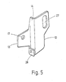
- Fig. 5 das Verbindungsstück des Auslegers nach Fig. 4 in einer perspektivischen Darstellung der anderen Seite und
- Fig. 6 den Ausleger nach Fig. 4 im montierten Zustand in einer Draufsicht.
- Fig. 1 zeigt eine Trag- und Aufhängevorrichtung 1 für Kabel, Rohre u.dgl., die entweder unmittelbar auf der Tragvorrichtung 1 oder in Pritschen und Rinnen angeordnet sind, die auf der Tragvorrichtung 1 gehaltert sind. Die Trag- und Aufhängevorrichtung 1 nach Fig. 1 ist an einer Struktur eines Gebäudes in Gestalt einer Decke 2 befestigt und enthält einen vertikal verlaufenden Stiel 3, an dem zu beiden Seiten in entgegengesetzte Richtung ragend mehrere Ausleger 4 gehaltert sind. Eine Ausführungsform der Ausleger 4 ist in den Fig. 2 und 3 im einzelnen dargestellt. Sie haben, wie die Figur erkennen läßt, ein im wesentlichen U- oder C-förmiges Querschnittsprofil mit einem im wesentlichen ebenen Rückenteil 5, an dessen oberer und an dessen unterer Kante rechtwinklig zu dem Rückenteil 5 zwei etwa gleich tiefe Flansche 6 und 7 angeformt sind, die sich in Längsrichtung des Rückenteils 5 über die gesamte Länge des Auslegers 4 erstrecken. Beide Flansche 6 und 7 weisen in dieselbe Richtung.
- Das Rückenteil 5 verjüngt sich, ausgehend von einem Ende 8 zu dem anderen entgegenliegenden Ende 9, derart, daß der obere und der untere Flansch 6 und 7 in Richtung auf das Ende 9 zueinander konvergieren. Um, wie Fig. 3 erkennen läßt, den Ausleger 4 an dem Stiel 3 zu befestigen, ist ein gekröpftes Knotenblech 11 vorgesehen, das zwei zueinander parallele Halteflansche 12 und 13 bildet, die durch ein rechtwinklig zu den beiden Halteflanschen 12 und 13 verlaufendes Zwischenstück 14 einstückig miteinander verbunden sind. Die Tiefe des Zwischenstücks 14 richtet sich, wie sich aus der weiter unten stehenden Beschreibung ergibt, nach der Gestalt des Stieles 3.
- Der Halteflansch 13 bildet auf seiner dem Ausleger 4 zugekehrten sichtbaren Außenseite 15 eine plane Anlagefläche für die zwischen den beiden Flanschen 6 und 7 befindliche Innenfläche des Rückenteils 5. Die Höhe des Halteflansches 13 entspricht im wesentlichen dem Abstand, den die beiden Flansche 6 und 7 des Auslegers 4 an dem Ende 8 haben, das im montierten Zustand dem Stiel 3 zugekehrt ist. Um den Halteflansch 13 mit dem Ausleger 4 zu verbinden, ist in dem Rückenteil 5 in der Nähe des oberen Flansches 6 eine Bohrung 16 enthalten, die mit einer korrespondierenden Bohrung 17 in dem Halteflansch 13 fluchtet. Durch die miteinander fluchtenden Bohrungen 16 und 17 führt eine Kopfschraube 18, auf deren Gewinde eine Mutter 19 aufgeschraubt ist. Der Kopf der Schraube 18 befindet sich auf der in Fig. 2 sichtbaren Außenseite des Auslegers 4, während die Mutter 19 auf der der Anlagefläche 15 gegenüberliegenden Fläche des Halteflansches 13 aufliegt.
- Die Schraube 18 wirkt bei Belastung des Auslegers 4 gleichsam als Scharnier- oder Drehpunkt und wird lediglich auf Scherung beansprucht. Die Drehmomente, die bei der Belastung des Auslegers 4 auftreten, werden, als Querkräfte, über eine Widerlagerkante 21 in den Stiel 3 eingeleitet. Die Widerlagerkante 21 befindet sich an dem dem Stiel 3 zugekehrten Ende 8 des Auslegers 4 und ist von dem unteren, schräg verlaufenden Flansch 9 gebildet. Der Abstand, den die Bohrung 16 von der hinteren Kante 8 aufweist, ist deswegen auch derart bemessen, daß, wenn die Widerlagerkante 21 an dem Stiel 3 anliegt, der obere Flansch 6 den gewünschten horizontalen Verlauf aufweist, also sich rechtwinklig zu dem Stiel 3 erstreckt.
- Der andere Halteflansch 12 dient der Befestigung des Verbindungsstückes an dem Stiel 3, dessen Querschnitt sich aus Fig. 3 ergibt. Der Stiel 3 ist durchgehend über seine gesamte Länge Z-förmig profiliert und enthält einen über die Längsrichtung durchgehenden Steg 22, an dessen in Längsrichtung durchgehende Kanten zwei Stielflansche 23 und 24 rechtwinklig zu dem Steg 22 verlaufend angeformt sind. Die beiden Stielflansche 23 und 24 erstrecken sich, bezogen auf die durch den Steg 22 definierte Ebene, in entgegengesetzten Richtungen und haben gegenüber dem Steg 22 dieselbe Höhe. An die Höhe dieser beiden Flansche 23 und 24 ist die Höhe des Zwischenstücks 14 des Verbindungsstücks 11 angepaßt, derart, daß im montierten Zustand die rechtwinklig zu der Längserstreckung des Auslegers 4 verlaufende Widerlagerkante 21 vor einem der beiden Stielflansche 23 und 24 zu liegen kommt.
- Der Stiel 3 enthält ferner in seinem Steg 22 eine Vielzahl äquidistant verteilter Löcher 25, die längs der Mittellinie des Steges angeordnet sind und die der Aufnahme einer Befestigungsschraube 26 dienen.
- Bei der Montage des beschriebenen Auslegers 4 wird nach der Befestigung des Stiels 3 an der Gebäudestruktur 2 ein Knotenblech 11 ausgewählt, das in der Lage ist, die an dem Ausleger 4 auftretende Kraft in den Stiel 3 einzuleiten. Das ausgesuchte Knotenblech 11 wird mit seinem Halteflansch 13 an dem Ausleger 4 befestigt, und zwar so, daß der Halteflansch 13 an dem Rückenteil 5 zwischen den beiden Flanschen 6 und 7 zu liegen kommt. Daran anschließend wird die Gewindeschraube 18 durch die miteinander fluchtende Bohrungen 16 und 17 gesteckt und es wird die Mutter 19 auf den Gewindebolzen 18 aufgeschraubt. Hierdurch wird zwischen dem Knotenblech 11 und dem Ausleger 4 eine formschlüssige Verbindung erhalten, die zunächst noch nicht in der Lage ist, ein Drehmoment zu übertragen. Diese Kraftaufnahmemöglichkeit entsteht erst, wenn der Ausleger 4 mittels des Verbindungsstückes 11 an dem Stiel 3 befestigt ist, wozu der Halteflansch 12 in der in Fig. 3 gezeigten Weise auf den Steg 22 des Stiels 3 aufgelegt wird. Da der Abstand, den ein in dem Halteflansch 12 vorgesehenes Langloch 27 von dem Zwischenstück 14 aufweist, etwa genau so groß ist, wie der Abstand der Löcher 25 in dem Stiel 3 von der von der Mittellinie wegweisenden Fläche des Stielflansches 24, wird, sobald die Befestigungsschraube 26 durch den Halteflansch 12 und den Stiel 13 hindurchgesteckt ist, der Ausleger 4 mit seiner Widerlagerkante 21 an dem Stielflansch 24 außen anliegend gehalten.
- Die Widerlagerkante 21 befindet sich, wie sich aus der Beschreibung ergibt, unterhalb des Schraubenbolzens 18, damit bei Belastung des Auslegers 4 von oben her durch eine Kraft, die bestrebt ist, den Ausleger 4 nach unten zu klappen, eine entsprechende Druckkraft von dem Widerlager 21 auf den Stielflansch 24 übertragen wird.
- Der an dem Stiel 3 befestigte Ausleger 4 ist damit in der Lage, sowohl Querkräfte als auch Drehmomente in den Stiel 3 einzuleiten.
- Falls ein Stiel 3 verwendet wird, der, wie Fig. 6 zeigt, dünnwandig ist und seine notwendige Biegesteifigkeit nur dadurch erhält, daß die Stielflansche 23 und 24 längs ihrer freien Kante nochmals nach innen umgefalzt sind, ist das in den Fig. 4 und 5 gezeigte Verbindungsstück 11 von Vorteil. Es gestattet nämlich, die von der Widerlagerkante ausgeübte Druckkraft auf einen größeren Bereich der Stielflansche 23 und 24 zu verteilen. Soweit in diesem Zusammenhang Bauteile und Elemente auftreten, die bereits vorher beschrieben sind, sind sie mit denselben Bezugszeichen versehen und nicht erneut erläutert. Das Verbindungsstück 11 nach den Fig. 4 und 6 trägt unterhalb des Halteflansches 13 eine Lasche 28, die durch U-förmiges Umbiegen eines entsprechenden Fortsatzes an dem Zwischenstück 14 gebildet ist und parallel und mit Abstand zu der dem Halteflansch 13 benachbarten Außenseite des Zwischenstückes 14 verläuft. Der Abstand, den die Lasche 28 von der Außenseite, d.h. der an den Halteflansch 13 angrenzenden Seite des Zwischenstückes 14 hat, entspricht der Stärke des Stielflansches 24 einschließlich der Stärke des eingefalzten Bereiches 29. Die Lage der Lasche 28 in vertikaler Richtung ist an die Höhe der Widerlagerkante 21 angepaßt, in der Weise, daß die von dem Stiel 3 wegweisende Fläche 31 der Lasche 28 mit der Widerlagerkante 21 zusammenwirken kann. Gemäß der hierdurch hervorgerufenen Verlagerung der Widerlagerkante 21 ist auch die Bohrung 17 in dem Halteflansch 13 von dem Zwischenstück 14 weggerückt.
- Die Montage des Auslegers 4 mit Hilfe des Verbindungsstückes 11 nach den Fig. 4 und 5 ist in Fig. 6 gezeigt. Während bei dem vorherigen Ausführungsbeispiel nach Fig. 3 das Verbindungsstück 11 um die zwischen dem Steg 22 und dem Stielflansch 24 bzw. 23 gebildete Kante außen herum gelegt ist, befindet sich bei Fig. 6 der Halteflansch 12 und das Zwischenstück 14 an dem Stiel 3 in dem Kehlbereich, der zwischen dem Steg 22 und dem Stielflansch 24 entsteht; der Abstand zwischen dem Loch 27 und dem Zwischenstück 14 ist derart gewählt, daß wiederum die Befestigungsschraube 26 eingesetzt werden kann. Diese Art der Befestigung hat den Vorteil, daß die Kräfte unmittelbar in den Stielflansch 23, 24 eingeleitet werden und die Schraube 26 weniger belastet wird.
- Bei dieser Art der Montage umgreift die Lasche 28 den Stielflansch 24 zusammen mit dem Zwischenstück 14 etwa gabelförmig von der Seite her. Da die Höhe der Lasche 28 der Lage der Widerlagerkante 21 entspricht, stützt sich der an dem Verbindungsstück 11 angebrachte Ausleger mit seiner Widerlagerkante 21 auf der Außenseite 31 der Lasche 28 ab. Hierdurch entsteht eine großflächige Belastung des Stielflansches 24, der auch bei geringer Wandstärke nicht eingedrückt werden kann. Die Tragfähigkeit ist entsprechend verbessert.
- Um letzteres zu erreichen, spielt es keine Rolle, ob der Ausleger 4, wie in den Fig. 2 und 3 gezeichnet, mit der Innenseite seines Rückenteils 5 auf dem Halteflansch 13 aufliegt oder ob er, wie Fig. 6 bzw. auch Fig. 4 erkennen läßt, mit seiner Außenseite an dem Halteflansch 13 anliegt.
- Zur Verstärkung des als Z-förmig gekröpftes Blechformteil ausgeführten Verbindungsstücks können noch Sicken 32, 33 vorgesehen sein, die sich über die Biegekanten, an denen die Halteflansche 12 und 13 mit dem Zwischenstück 14 zusammenhängen, hinaus erstrecken. Die Richtung, in der die Sicken 32, 33 erhaben sind, richtet sich danach, ob eine Montageart nach Fig. 3 oder Fig. 6 in Frage kommt.
- Bei allen gezeigten Ausführungsformen können an der Baustelle die Art des Verbindungsstücks 11 und des verwendeten Trägers 4 frei gewählt und an die Geometrie des Stieles 3 auf diese Weise leicht angepaßt werden.
- Eine herstellerseitige breite Lagerhaltung für alle Kombinationsmöglichkeiten, die eine starre unlösbare Verbindung zwischen dem Verbindungsstück 11 und dem Ausleger 4 mit sich bringen würde, entfällt.
- Wiewohl die neue Anordnung nur in Verbindung mit Z-förmigen Stielen gezeigt ist, ist ohne weiteres klar, daß sie auch in Verbindung mit H-Stielen einzusetzen ist.
Claims (12)
Applications Claiming Priority (2)
| Application Number | Priority Date | Filing Date | Title |
|---|---|---|---|
| DE3809079A DE3809079A1 (de) | 1988-03-18 | 1988-03-18 | Ausleger fuer trag- oder aufhaengevorrichtungen fuer kabel, rohre u. dgl. |
| DE3809079 | 1988-03-18 |
Publications (3)
| Publication Number | Publication Date |
|---|---|
| EP0332746A2 true EP0332746A2 (de) | 1989-09-20 |
| EP0332746A3 EP0332746A3 (en) | 1990-10-24 |
| EP0332746B1 EP0332746B1 (de) | 1994-06-01 |
Family
ID=6350066
Family Applications (1)
| Application Number | Title | Priority Date | Filing Date |
|---|---|---|---|
| EP88118552A Expired - Lifetime EP0332746B1 (de) | 1988-03-18 | 1988-11-08 | Ausleger für Trag- oder Aufhängevorrichtungen für Kabel, Rohre und dergleiche |
Country Status (3)
| Country | Link |
|---|---|
| EP (1) | EP0332746B1 (de) |
| AT (1) | ATE106628T1 (de) |
| DE (2) | DE3809079A1 (de) |
Cited By (2)
| Publication number | Priority date | Publication date | Assignee | Title |
|---|---|---|---|---|
| EP0575269A1 (de) * | 1992-06-17 | 1993-12-22 | Mavil | Aufhängevorrichtung für Kabelkanäle |
| US7055786B2 (en) * | 2002-02-06 | 2006-06-06 | Legrand S.P.A | Device for fixing mesh cable trays to a support bracket |
Families Citing this family (5)
| Publication number | Priority date | Publication date | Assignee | Title |
|---|---|---|---|---|
| DE3804940C1 (de) * | 1988-02-17 | 1989-01-26 | Franz 6200 Wiesbaden De Mueller | |
| CH701791A1 (de) * | 2009-09-01 | 2011-03-15 | Zurecon Ag | Ausleger. |
| ES1248154Y (es) * | 2020-04-17 | 2020-09-22 | Unex Aparellaje Electrico Sl | Escuadra de soporte para bandejas portacables |
| CN112008678A (zh) * | 2020-08-25 | 2020-12-01 | 上海宝冶建筑工程有限公司 | 一种定型化管件堆放架 |
| DE202021104125U1 (de) * | 2021-08-03 | 2022-11-04 | OBO Bettermann Produktion Deutschland GmbH & Co. KG | Baugruppe eines Kabeltragsystems |
Family Cites Families (8)
| Publication number | Priority date | Publication date | Assignee | Title |
|---|---|---|---|---|
| DE1236041B (de) * | 1965-07-09 | 1967-03-09 | Neuwalzwerk Boesperde Nachf Be | Haltevorrichtung fuer elektrische Kabel |
| FR2067618A5 (de) * | 1969-11-12 | 1971-08-20 | Electro Entreprise | |
| DE2002988C3 (de) * | 1970-01-23 | 1978-10-05 | Schweizer Geb. Wilden, Ingeborg, Oberwil, Basel (Schweiz) | Tragvorrichtung für Kabel |
| FR2234503A1 (de) * | 1973-06-20 | 1975-01-17 | Heer & Co | |
| CH564264A5 (de) * | 1974-01-28 | 1975-07-15 | Heer & Co | |
| FR2450523A1 (fr) * | 1979-03-02 | 1980-09-26 | Cit Alcatel | Repartiteur d'infrastructure |
| GB2114820A (en) * | 1982-02-08 | 1983-08-24 | Gkn Australia Ltd | Cable ladder |
| FR2529641A1 (fr) * | 1982-06-30 | 1984-01-06 | Seine Const Elect | Consoles reversibles pour chemins de cables |
-
1988
- 1988-03-18 DE DE3809079A patent/DE3809079A1/de active Granted
- 1988-11-08 DE DE3889902T patent/DE3889902D1/de not_active Expired - Fee Related
- 1988-11-08 EP EP88118552A patent/EP0332746B1/de not_active Expired - Lifetime
- 1988-11-08 AT AT88118552T patent/ATE106628T1/de not_active IP Right Cessation
Cited By (2)
| Publication number | Priority date | Publication date | Assignee | Title |
|---|---|---|---|---|
| EP0575269A1 (de) * | 1992-06-17 | 1993-12-22 | Mavil | Aufhängevorrichtung für Kabelkanäle |
| US7055786B2 (en) * | 2002-02-06 | 2006-06-06 | Legrand S.P.A | Device for fixing mesh cable trays to a support bracket |
Also Published As
| Publication number | Publication date |
|---|---|
| DE3809079C2 (de) | 1989-09-21 |
| EP0332746B1 (de) | 1994-06-01 |
| EP0332746A3 (en) | 1990-10-24 |
| DE3889902D1 (de) | 1994-07-07 |
| ATE106628T1 (de) | 1994-06-15 |
| DE3809079A1 (de) | 1988-08-11 |
Similar Documents
| Publication | Publication Date | Title |
|---|---|---|
| EP2132388B1 (de) | Belageinheit mit abhebesicherung und verfahren zur sicherung einer belageinheit gegen abheben sowie verfahren zur entsicherung einer gegen abheben gesicherten belageinheit | |
| EP3384105B1 (de) | Tragvorrichtung aus metall zum aufhängen eines hängegerüsts oder einer anderen hängekonstruktion | |
| EP3985189B1 (de) | Verbinder für zwei werkstücke | |
| EP4251824A1 (de) | Anordnung von gerüstbauteilen | |
| DE2508592C3 (de) | Konsole zum Anschluß eines Trägers an eine Stütze in Stahlskelett-Hochbauten | |
| DE3809079C2 (de) | ||
| DE19908388B4 (de) | Bauelement zur Wärmedämmung | |
| EP4131682A1 (de) | Kopfanschlussteil zum befestigen eines hängestiels eines kabeltragsystems an einer decke | |
| EP0826850B1 (de) | Fassadenunterkonstruktion | |
| DE2732183C3 (de) | Verbindung zweier mit ihren Stirnflächen einander gegenüberliegenden Stahlbetonteile | |
| DE3438418A1 (de) | Stuetzen- oder rahmenanordnung fuer regalsysteme | |
| DE2942566A1 (de) | Traeger | |
| DE2145021C3 (de) | Dachbindereinheit für Winterbauhallen | |
| DD290925A5 (de) | Justierbares kopfplatten-zwischenbauteil | |
| DE102021120323B4 (de) | Endseitig einseitig abgestützter Ausleger für ein Kabeltragsystem | |
| DE19521441B4 (de) | Befestigungsanordnung für eine Ladeheckklappe an einem Lastkraftwagen | |
| DE19623957C1 (de) | Als Blechformteil hergestellte Kopfplatte | |
| DE2836817A1 (de) | Vorrichtung zur aufhaengung einer fassadenplatte an einem hinterluefteten baukoerper | |
| DE3814912C2 (de) | ||
| EP0593017A1 (de) | Verbindungsteil | |
| DE19617996A1 (de) | Befestigungsvorrichtung für eine Hubladebühne | |
| EP0813278B1 (de) | Als Blechformteil hergestellte Kopfplatte | |
| EP0723927A1 (de) | Anhängevorrichtung zum Anhängen wenigstens einer Schaltafel an ein Hebezeug | |
| DE2731682C3 (de) | Befestigungsvorrichtung für die Kragarme von Wartungsbalkonen an Gebäudefassaden | |
| DE9204010U1 (de) | Abhängevorrichtung für Tragschienen von Unterkonstruktionen für Unterdecken |
Legal Events
| Date | Code | Title | Description |
|---|---|---|---|
| PUAI | Public reference made under article 153(3) epc to a published international application that has entered the european phase |
Free format text: ORIGINAL CODE: 0009012 |
|
| AK | Designated contracting states |
Kind code of ref document: A2 Designated state(s): AT BE CH DE ES FR GB GR IT LI LU NL SE |
|
| PUAL | Search report despatched |
Free format text: ORIGINAL CODE: 0009013 |
|
| AK | Designated contracting states |
Kind code of ref document: A3 Designated state(s): AT BE CH DE ES FR GB GR IT LI LU NL SE |
|
| 17P | Request for examination filed |
Effective date: 19910316 |
|
| 17Q | First examination report despatched |
Effective date: 19921109 |
|
| GRAA | (expected) grant |
Free format text: ORIGINAL CODE: 0009210 |
|
| AK | Designated contracting states |
Kind code of ref document: B1 Designated state(s): AT BE CH DE ES FR GB GR IT LI LU NL SE |
|
| PG25 | Lapsed in a contracting state [announced via postgrant information from national office to epo] |
Ref country code: IT Free format text: LAPSE BECAUSE OF FAILURE TO SUBMIT A TRANSLATION OF THE DESCRIPTION OR TO PAY THE FEE WITHIN THE PRE;WARNING: LAPSES OF ITALIAN PATENTS WITH EFFECTIVE DATE BEFORE 2007 MAY HAVE OCCURRED AT ANY TIME BEFORE 2007. THE CORRECT EFFECTIVE DATE MAY BE DIFFERENT FROM THE ONE RECORDED.SCRIBED TIME-LIMIT Effective date: 19940601 Ref country code: ES Free format text: THE PATENT HAS BEEN ANNULLED BY A DECISION OF A NATIONAL AUTHORITY Effective date: 19940601 Ref country code: GB Effective date: 19940601 Ref country code: GR Free format text: LAPSE BECAUSE OF FAILURE TO SUBMIT A TRANSLATION OF THE DESCRIPTION OR TO PAY THE FEE WITHIN THE PRESCRIBED TIME-LIMIT Effective date: 19940601 |
|
| REF | Corresponds to: |
Ref document number: 106628 Country of ref document: AT Date of ref document: 19940615 Kind code of ref document: T |
|
| ET | Fr: translation filed | ||
| REF | Corresponds to: |
Ref document number: 3889902 Country of ref document: DE Date of ref document: 19940707 |
|
| PG25 | Lapsed in a contracting state [announced via postgrant information from national office to epo] |
Ref country code: SE Effective date: 19940901 |
|
| PGFP | Annual fee paid to national office [announced via postgrant information from national office to epo] |
Ref country code: AT Payment date: 19941013 Year of fee payment: 7 |
|
| PGFP | Annual fee paid to national office [announced via postgrant information from national office to epo] |
Ref country code: BE Payment date: 19941014 Year of fee payment: 7 |
|
| PGFP | Annual fee paid to national office [announced via postgrant information from national office to epo] |
Ref country code: FR Payment date: 19941021 Year of fee payment: 7 |
|
| PGFP | Annual fee paid to national office [announced via postgrant information from national office to epo] |
Ref country code: CH Payment date: 19941129 Year of fee payment: 7 |
|
| PG25 | Lapsed in a contracting state [announced via postgrant information from national office to epo] |
Ref country code: LU Free format text: LAPSE BECAUSE OF NON-PAYMENT OF DUE FEES Effective date: 19941130 |
|
| PGFP | Annual fee paid to national office [announced via postgrant information from national office to epo] |
Ref country code: NL Payment date: 19941130 Year of fee payment: 7 |
|
| GBV | Gb: ep patent (uk) treated as always having been void in accordance with gb section 77(7)/1977 [no translation filed] |
Effective date: 19940601 |
|
| PGFP | Annual fee paid to national office [announced via postgrant information from national office to epo] |
Ref country code: DE Payment date: 19950117 Year of fee payment: 7 |
|
| PLBE | No opposition filed within time limit |
Free format text: ORIGINAL CODE: 0009261 |
|
| STAA | Information on the status of an ep patent application or granted ep patent |
Free format text: STATUS: NO OPPOSITION FILED WITHIN TIME LIMIT |
|
| 26N | No opposition filed | ||
| PG25 | Lapsed in a contracting state [announced via postgrant information from national office to epo] |
Ref country code: AT Effective date: 19951108 |
|
| PG25 | Lapsed in a contracting state [announced via postgrant information from national office to epo] |
Ref country code: BE Effective date: 19951130 Ref country code: CH Effective date: 19951130 Ref country code: LI Effective date: 19951130 |
|
| BERE | Be: lapsed |
Owner name: RIETH & CO. G.M.B.H. Effective date: 19951130 |
|
| PG25 | Lapsed in a contracting state [announced via postgrant information from national office to epo] |
Ref country code: NL Effective date: 19960601 |
|
| REG | Reference to a national code |
Ref country code: CH Ref legal event code: PL |
|
| PG25 | Lapsed in a contracting state [announced via postgrant information from national office to epo] |
Ref country code: FR Effective date: 19960731 |
|
| NLV4 | Nl: lapsed or anulled due to non-payment of the annual fee |
Effective date: 19960601 |
|
| PG25 | Lapsed in a contracting state [announced via postgrant information from national office to epo] |
Ref country code: DE Effective date: 19960801 |
|
| REG | Reference to a national code |
Ref country code: FR Ref legal event code: ST |