EP0332746A2 - Console latérale pour dispositif de support ou de suspension pour câbles tuyaux et objets similaires - Google Patents
Console latérale pour dispositif de support ou de suspension pour câbles tuyaux et objets similaires Download PDFInfo
- Publication number
- EP0332746A2 EP0332746A2 EP88118552A EP88118552A EP0332746A2 EP 0332746 A2 EP0332746 A2 EP 0332746A2 EP 88118552 A EP88118552 A EP 88118552A EP 88118552 A EP88118552 A EP 88118552A EP 0332746 A2 EP0332746 A2 EP 0332746A2
- Authority
- EP
- European Patent Office
- Prior art keywords
- boom
- stem
- flange
- connecting piece
- web
- Prior art date
- Legal status (The legal status is an assumption and is not a legal conclusion. Google has not performed a legal analysis and makes no representation as to the accuracy of the status listed.)
- Granted
Links
Images


Classifications
-
- H—ELECTRICITY
- H02—GENERATION; CONVERSION OR DISTRIBUTION OF ELECTRIC POWER
- H02G—INSTALLATION OF ELECTRIC CABLES OR LINES, OR OF COMBINED OPTICAL AND ELECTRIC CABLES OR LINES
- H02G3/00—Installations of electric cables or lines or protective tubing therefor in or on buildings, equivalent structures or vehicles
- H02G3/26—Installations of cables, lines, or separate protective tubing therefor directly on or in walls, ceilings, or floors
- H02G3/263—Installation, e.g. suspension, of conduit channels or other supports
-
- A—HUMAN NECESSITIES
- A47—FURNITURE; DOMESTIC ARTICLES OR APPLIANCES; COFFEE MILLS; SPICE MILLS; SUCTION CLEANERS IN GENERAL
- A47B—TABLES; DESKS; OFFICE FURNITURE; CABINETS; DRAWERS; GENERAL DETAILS OF FURNITURE
- A47B57/00—Cabinets, racks or shelf units, characterised by features for adjusting shelves or partitions
- A47B57/30—Cabinets, racks or shelf units, characterised by features for adjusting shelves or partitions with means for adjusting the height of detachable shelf supports
- A47B57/44—Cabinets, racks or shelf units, characterised by features for adjusting shelves or partitions with means for adjusting the height of detachable shelf supports consisting of screwbolts as connecting members
- A47B57/46—Cabinets, racks or shelf units, characterised by features for adjusting shelves or partitions with means for adjusting the height of detachable shelf supports consisting of screwbolts as connecting members the shelf supports being cantilever brackets
-
- F—MECHANICAL ENGINEERING; LIGHTING; HEATING; WEAPONS; BLASTING
- F16—ENGINEERING ELEMENTS AND UNITS; GENERAL MEASURES FOR PRODUCING AND MAINTAINING EFFECTIVE FUNCTIONING OF MACHINES OR INSTALLATIONS; THERMAL INSULATION IN GENERAL
- F16L—PIPES; JOINTS OR FITTINGS FOR PIPES; SUPPORTS FOR PIPES, CABLES OR PROTECTIVE TUBING; MEANS FOR THERMAL INSULATION IN GENERAL
- F16L3/00—Supports for pipes, cables or protective tubing, e.g. hangers, holders, clamps, cleats, clips, brackets
- F16L3/24—Supports for pipes, cables or protective tubing, e.g. hangers, holders, clamps, cleats, clips, brackets with special member for attachment to profiled girders
- F16L3/243—Supports for pipes, cables or protective tubing, e.g. hangers, holders, clamps, cleats, clips, brackets with special member for attachment to profiled girders the special member being inserted in the profiled girder
Definitions
- the invention relates to a carrying or hanging device for cables, pipes and the like. with the features of the preamble of claim 1.
- brackets In such support or suspension devices known from practice, there is a cohesive, mostly welded connection between the connecting piece and the boom, which is capable of introducing both the transverse forces and the bending moments from the boom into the arm.
- This very robust and, in itself, simple, automatically established connection between the connecting piece and the bracket cannot be changed subsequently.
- brackets There are also different stick geometries to which the brackets are to be attached. The range of bracket and connector combinations to be kept in stock is correspondingly large if both are permanently connected by the manufacturer.
- the corrosion protection for example in the form of galvanizing, can be applied only at the very end, since galvanized parts are welded on the one hand toxic fumes are generated and on the other hand the zinc layer burns away in the vicinity of the weld so that it is otherwise unprotected. It is therefore impossible to manufacture the parts from semi-finished products (coil) that have already been galvanized.
- the connecting piece and the bracket in one piece.
- the wall thickness of the material used must depend on the part on which the greatest forces occur, namely the connecting piece.
- the boom is then usually very oversized, but this does not contribute to strength, but only increases the material costs.
- the connecting piece consists of an approximately Z-shaped bent sheet metal part in order to bring the flanges of the bracket into the region of the flange of the stick when the connecting piece is attached to the web of the stick.
- the bolt-shaped connecting element is a threaded screw with a screwed-on nut, which does not even have to be tightened in order to fulfill the function. Slight hand tightening is all it takes to transfer the shear forces that occur.
- the connecting piece has a tab which lies between the abutment edge of the boom and the flange of the stick.
- the force emanating from the abutment edge of the boom is thus distributed over a larger area on the stick.
- this embodiment of the connecting piece permits the use of thin-walled stems in which the necessary bending stiffness is obtained by multiple bending in the longitudinal direction. Although this saves weight, it makes the handles sensitive to lateral denting when excessive forces occur on surfaces that are too small, such as the edges of outrigger arms.
- FIGS. 2 and 3 show a carrying and hanging device 1 for cables, pipes and the like, which are either arranged directly on the carrying device 1 or in platforms and channels which are held on the carrying device 1.
- 1 is fastened to a structure of a building in the form of a ceiling 2 and contains a vertically extending handle 3, on which a plurality of brackets 4 are supported so as to protrude in opposite directions on both sides.
- An embodiment of the boom 4 is shown in FIGS. 2 and 3 in detail.
- the back part 5 tapers, starting from one end 8 to the other opposite end 9, such that the upper and lower flanges 6 and 7 converge towards one another in the direction of the end 9.
- a cranked gusset plate 11 is provided, which forms two mutually parallel holding flanges 12 and 13, which are formed by an intermediate piece 14 running at right angles to the two holding flanges 12 and 13 are integrally connected.
- the depth of the intermediate piece 14 depends, as can be seen from the description below, on the shape of the handle 3.
- the holding flange 13 forms on its outer side 15 facing the arm 4 a flat contact surface for the inner surface of the back part 5 located between the two flanges 6 and 7.
- the height of the holding flange 13 corresponds essentially to the distance that the two flanges 6 and 7 of the Boom 4 at the end 8, which faces the arm 3 in the assembled state.
- a bore 16 is contained in the back part 5 in the vicinity of the upper flange 6, which bore is aligned with a corresponding bore 17 in the holding flange 13.
- the head of the screw 18 is located on the outside of the arm 4 visible in FIG. 2, while the nut 19 rests on the surface of the holding flange 13 opposite the contact surface 15.
- the screw 18 acts as a hinge or fulcrum and is only subjected to shear stress.
- the torques that occur when the boom 4 is loaded are introduced as lateral forces into the arm 3 via an abutment edge 21.
- the abutment edge 21 is located at the end 8 of the boom 4 facing the arm 3 and is formed by the lower, oblique flange 9.
- the distance that the bore 16 has from the rear edge 8 is therefore also dimensioned such that when the abutment edge 21 abuts the stem 3, the upper flange 6 has the desired horizontal course, that is to say extends at right angles to the stem 3 .
- the other holding flange 12 is used to fasten the connecting piece to the stem 3, the cross section of which results from FIG. 3.
- the stem 3 is profiled continuously over its entire length in a Z-shape and contains a web 22 which is continuous over the longitudinal direction, on the edges of which in the longitudinal direction two stem flanges 23 and 24 are integrally formed extending at right angles to the web 22.
- the two stem flanges 23 and 24 extend, in relation to the plane defined by the web 22, in opposite directions and have the same height in relation to the web 22.
- the height of the intermediate piece 14 of the connecting piece 11 is adapted to the height of these two flanges 23 and 24, such that in the assembled state the abutment edge 21, which extends at right angles to the longitudinal extension of the boom 4, comes to rest in front of one of the two stem flanges 23 and 24.
- the stem 3 also contains in its web 22 a plurality of equidistantly distributed holes 25 which are arranged along the center line of the web and which serve to receive a fastening screw 26.
- a gusset plate 11 is selected after the attachment of the arm 3 to the building structure 2, which is capable of introducing the force occurring on the arm 4 into the arm 3.
- the selected gusset plate 11 is fastened with its holding flange 13 to the bracket 4, in such a way that the holding flange 13 comes to rest on the back part 5 between the two flanges 6 and 7.
- the threaded screw 18 is inserted through the mutually aligned bores 16 and 17 and the nut 19 is screwed onto the threaded bolt 18. This will between receive the gusset plate 11 and the bracket 4 a positive connection, which is initially not yet able to transmit a torque.
- the abutment edge 21 is, as can be seen from the description, below the screw bolt 18, so that when the boom 4 is loaded from above by a force which tends to fold the boom 4 down, a corresponding pressure force from the abutment 21 is transferred to the stem flange 24.
- the boom 4 attached to the arm 3 is thus capable of introducing both lateral forces and torques into the arm 3.
- connector 11 is advantageous. It allows namely that of the Distribute abutment edge pressure applied to a larger area of the stem flanges 23 and 24. Insofar as components and elements that have already been described previously occur in this context, they are provided with the same reference symbols and are not explained again.
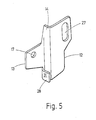
- a tab 28 below the holding flange 13 which is formed by U-shaped bending of a corresponding extension on the intermediate piece 14 and runs parallel and at a distance from the outside of the intermediate piece 14 adjacent to the holding flange 13 .
- the distance that the tab 28 has from the outside, ie the side of the intermediate piece 14 adjoining the holding flange 13, corresponds to the thickness of the stem flange 24 including the thickness of the folded-in area 29.
- the position of the tab 28 in the vertical direction is vertical adapted to the abutment edge 21 in such a way that the surface 31 of the tab 28 pointing away from the handle 3 can interact with the abutment edge 21. According to the resulting displacement of the abutment edge 21, the bore 17 in the holding flange 13 has also moved away from the intermediate piece 14.
- FIG. 6 The assembly of the boom 4 with the aid of the connecting piece 11 according to FIGS. 4 and 5 is shown in FIG. 6. 3, the connecting piece 11 is placed around the edge formed between the web 22 and the stem flange 24 and 23 on the outside, in FIG. 6 the holding flange 12 and the intermediate piece 14 are located on the stem 3 in the throat area that arises between the web 22 and the stem flange 24; the distance between the hole 27 and the intermediate piece 14 is selected such that the fastening screw 26 can be used again.
- This type of attachment has the advantage that the forces are introduced directly into the stem flange 23, 24 and the screw 26 is less stressed.
- the tab 28 engages around the stem flange 24 together with the intermediate piece 14 approximately in a fork shape from the side. Since the height of the tab 28 corresponds to the position of the abutment edge 21, the bracket attached to the connecting piece 11 is supported with its abutment edge 21 on the outside 31 of the tab 28. This creates a large-area load on the stem flange 24, which cannot be pressed in even with a small wall thickness. The load capacity is improved accordingly.
- beads 32, 33 can also be provided, which extend beyond the bending edges on which the holding flanges 12 and 13 are connected to the intermediate piece 14.
- the direction in which the beads 32, 33 are raised depends on whether an assembly type according to FIG. 3 or 6 is possible.
- the type of connecting piece 11 and the support 4 used can be freely selected at the construction site and can be easily adapted to the geometry of the stem 3 in this way.
Landscapes
- Engineering & Computer Science (AREA)
- General Engineering & Computer Science (AREA)
- Architecture (AREA)
- Civil Engineering (AREA)
- Structural Engineering (AREA)
- Mechanical Engineering (AREA)
- Supports For Pipes And Cables (AREA)
- Joining Of Building Structures In Genera (AREA)
- Clamps And Clips (AREA)
- Jib Cranes (AREA)
Applications Claiming Priority (2)
| Application Number | Priority Date | Filing Date | Title |
|---|---|---|---|
| DE3809079A DE3809079A1 (de) | 1988-03-18 | 1988-03-18 | Ausleger fuer trag- oder aufhaengevorrichtungen fuer kabel, rohre u. dgl. |
| DE3809079 | 1988-03-18 |
Publications (3)
| Publication Number | Publication Date |
|---|---|
| EP0332746A2 true EP0332746A2 (fr) | 1989-09-20 |
| EP0332746A3 EP0332746A3 (en) | 1990-10-24 |
| EP0332746B1 EP0332746B1 (fr) | 1994-06-01 |
Family
ID=6350066
Family Applications (1)
| Application Number | Title | Priority Date | Filing Date |
|---|---|---|---|
| EP88118552A Expired - Lifetime EP0332746B1 (fr) | 1988-03-18 | 1988-11-08 | Console latérale pour dispositif de support ou de suspension pour câbles tuyaux et objets similaires |
Country Status (3)
| Country | Link |
|---|---|
| EP (1) | EP0332746B1 (fr) |
| AT (1) | ATE106628T1 (fr) |
| DE (2) | DE3809079A1 (fr) |
Cited By (2)
| Publication number | Priority date | Publication date | Assignee | Title |
|---|---|---|---|---|
| EP0575269A1 (fr) * | 1992-06-17 | 1993-12-22 | Mavil | Dispositif pour suspendre les chemins de câbles |
| US7055786B2 (en) * | 2002-02-06 | 2006-06-06 | Legrand S.P.A | Device for fixing mesh cable trays to a support bracket |
Families Citing this family (5)
| Publication number | Priority date | Publication date | Assignee | Title |
|---|---|---|---|---|
| DE3804940C1 (fr) * | 1988-02-17 | 1989-01-26 | Franz 6200 Wiesbaden De Mueller | |
| CH701791A1 (de) * | 2009-09-01 | 2011-03-15 | Zurecon Ag | Ausleger. |
| ES1248154Y (es) * | 2020-04-17 | 2020-09-22 | Unex Aparellaje Electrico Sl | Escuadra de soporte para bandejas portacables |
| CN112008678A (zh) * | 2020-08-25 | 2020-12-01 | 上海宝冶建筑工程有限公司 | 一种定型化管件堆放架 |
| DE202021104125U1 (de) * | 2021-08-03 | 2022-11-04 | OBO Bettermann Produktion Deutschland GmbH & Co. KG | Baugruppe eines Kabeltragsystems |
Family Cites Families (8)
| Publication number | Priority date | Publication date | Assignee | Title |
|---|---|---|---|---|
| DE1236041B (de) * | 1965-07-09 | 1967-03-09 | Neuwalzwerk Boesperde Nachf Be | Haltevorrichtung fuer elektrische Kabel |
| FR2067618A5 (fr) * | 1969-11-12 | 1971-08-20 | Electro Entreprise | |
| DE2002988C3 (de) * | 1970-01-23 | 1978-10-05 | Schweizer Geb. Wilden, Ingeborg, Oberwil, Basel (Schweiz) | Tragvorrichtung für Kabel |
| FR2234503A1 (fr) * | 1973-06-20 | 1975-01-17 | Heer & Co | |
| CH564264A5 (fr) * | 1974-01-28 | 1975-07-15 | Heer & Co | |
| FR2450523A1 (fr) * | 1979-03-02 | 1980-09-26 | Cit Alcatel | Repartiteur d'infrastructure |
| GB2114820A (en) * | 1982-02-08 | 1983-08-24 | Gkn Australia Ltd | Cable ladder |
| FR2529641A1 (fr) * | 1982-06-30 | 1984-01-06 | Seine Const Elect | Consoles reversibles pour chemins de cables |
-
1988
- 1988-03-18 DE DE3809079A patent/DE3809079A1/de active Granted
- 1988-11-08 DE DE3889902T patent/DE3889902D1/de not_active Expired - Fee Related
- 1988-11-08 EP EP88118552A patent/EP0332746B1/fr not_active Expired - Lifetime
- 1988-11-08 AT AT88118552T patent/ATE106628T1/de not_active IP Right Cessation
Cited By (2)
| Publication number | Priority date | Publication date | Assignee | Title |
|---|---|---|---|---|
| EP0575269A1 (fr) * | 1992-06-17 | 1993-12-22 | Mavil | Dispositif pour suspendre les chemins de câbles |
| US7055786B2 (en) * | 2002-02-06 | 2006-06-06 | Legrand S.P.A | Device for fixing mesh cable trays to a support bracket |
Also Published As
| Publication number | Publication date |
|---|---|
| DE3809079C2 (fr) | 1989-09-21 |
| EP0332746B1 (fr) | 1994-06-01 |
| EP0332746A3 (en) | 1990-10-24 |
| DE3889902D1 (de) | 1994-07-07 |
| ATE106628T1 (de) | 1994-06-15 |
| DE3809079A1 (de) | 1988-08-11 |
Similar Documents
| Publication | Publication Date | Title |
|---|---|---|
| EP2132388B1 (fr) | Plaque de sol avec protection contre les soulèvements, et procédé de protection d'une plaque de sol contre les soulèvements, et procédé de déverrouillage d'une plaque de sol protégée contre les soulèvements | |
| EP3384105B1 (fr) | Dispositif de support en métal servant à suspendre un échafaudage suspendu ou une autre structure suspendue | |
| EP3985189B1 (fr) | Connecteur pour deux pièces | |
| EP4251824A1 (fr) | Agencement de composants d'échafaudage | |
| DE2508592C3 (de) | Konsole zum Anschluß eines Trägers an eine Stütze in Stahlskelett-Hochbauten | |
| DE3809079C2 (fr) | ||
| DE19908388B4 (de) | Bauelement zur Wärmedämmung | |
| EP4131682A1 (fr) | Pièce tête de liaison permettant de fixer une tige de suspension d'un système de porte-câble à un plafond | |
| EP0826850B1 (fr) | Elément porteur pour façade | |
| DE2732183C3 (de) | Verbindung zweier mit ihren Stirnflächen einander gegenüberliegenden Stahlbetonteile | |
| DE3438418A1 (de) | Stuetzen- oder rahmenanordnung fuer regalsysteme | |
| DE2942566A1 (de) | Traeger | |
| DE2145021C3 (de) | Dachbindereinheit für Winterbauhallen | |
| DD290925A5 (de) | Justierbares kopfplatten-zwischenbauteil | |
| DE102021120323B4 (de) | Endseitig einseitig abgestützter Ausleger für ein Kabeltragsystem | |
| DE19521441B4 (de) | Befestigungsanordnung für eine Ladeheckklappe an einem Lastkraftwagen | |
| DE19623957C1 (de) | Als Blechformteil hergestellte Kopfplatte | |
| DE2836817A1 (de) | Vorrichtung zur aufhaengung einer fassadenplatte an einem hinterluefteten baukoerper | |
| DE3814912C2 (fr) | ||
| EP0593017A1 (fr) | Pièce de raccordement | |
| DE19617996A1 (de) | Befestigungsvorrichtung für eine Hubladebühne | |
| EP0813278B1 (fr) | Plaque de tête en tôle préformée | |
| EP0723927A1 (fr) | Dispositif de suspension pour suspendre au moins un panneau de coffrage à un appareil de levage | |
| DE2731682C3 (de) | Befestigungsvorrichtung für die Kragarme von Wartungsbalkonen an Gebäudefassaden | |
| DE9204010U1 (de) | Abhängevorrichtung für Tragschienen von Unterkonstruktionen für Unterdecken |
Legal Events
| Date | Code | Title | Description |
|---|---|---|---|
| PUAI | Public reference made under article 153(3) epc to a published international application that has entered the european phase |
Free format text: ORIGINAL CODE: 0009012 |
|
| AK | Designated contracting states |
Kind code of ref document: A2 Designated state(s): AT BE CH DE ES FR GB GR IT LI LU NL SE |
|
| PUAL | Search report despatched |
Free format text: ORIGINAL CODE: 0009013 |
|
| AK | Designated contracting states |
Kind code of ref document: A3 Designated state(s): AT BE CH DE ES FR GB GR IT LI LU NL SE |
|
| 17P | Request for examination filed |
Effective date: 19910316 |
|
| 17Q | First examination report despatched |
Effective date: 19921109 |
|
| GRAA | (expected) grant |
Free format text: ORIGINAL CODE: 0009210 |
|
| AK | Designated contracting states |
Kind code of ref document: B1 Designated state(s): AT BE CH DE ES FR GB GR IT LI LU NL SE |
|
| PG25 | Lapsed in a contracting state [announced via postgrant information from national office to epo] |
Ref country code: IT Free format text: LAPSE BECAUSE OF FAILURE TO SUBMIT A TRANSLATION OF THE DESCRIPTION OR TO PAY THE FEE WITHIN THE PRE;WARNING: LAPSES OF ITALIAN PATENTS WITH EFFECTIVE DATE BEFORE 2007 MAY HAVE OCCURRED AT ANY TIME BEFORE 2007. THE CORRECT EFFECTIVE DATE MAY BE DIFFERENT FROM THE ONE RECORDED.SCRIBED TIME-LIMIT Effective date: 19940601 Ref country code: ES Free format text: THE PATENT HAS BEEN ANNULLED BY A DECISION OF A NATIONAL AUTHORITY Effective date: 19940601 Ref country code: GB Effective date: 19940601 Ref country code: GR Free format text: LAPSE BECAUSE OF FAILURE TO SUBMIT A TRANSLATION OF THE DESCRIPTION OR TO PAY THE FEE WITHIN THE PRESCRIBED TIME-LIMIT Effective date: 19940601 |
|
| REF | Corresponds to: |
Ref document number: 106628 Country of ref document: AT Date of ref document: 19940615 Kind code of ref document: T |
|
| ET | Fr: translation filed | ||
| REF | Corresponds to: |
Ref document number: 3889902 Country of ref document: DE Date of ref document: 19940707 |
|
| PG25 | Lapsed in a contracting state [announced via postgrant information from national office to epo] |
Ref country code: SE Effective date: 19940901 |
|
| PGFP | Annual fee paid to national office [announced via postgrant information from national office to epo] |
Ref country code: AT Payment date: 19941013 Year of fee payment: 7 |
|
| PGFP | Annual fee paid to national office [announced via postgrant information from national office to epo] |
Ref country code: BE Payment date: 19941014 Year of fee payment: 7 |
|
| PGFP | Annual fee paid to national office [announced via postgrant information from national office to epo] |
Ref country code: FR Payment date: 19941021 Year of fee payment: 7 |
|
| PGFP | Annual fee paid to national office [announced via postgrant information from national office to epo] |
Ref country code: CH Payment date: 19941129 Year of fee payment: 7 |
|
| PG25 | Lapsed in a contracting state [announced via postgrant information from national office to epo] |
Ref country code: LU Free format text: LAPSE BECAUSE OF NON-PAYMENT OF DUE FEES Effective date: 19941130 |
|
| PGFP | Annual fee paid to national office [announced via postgrant information from national office to epo] |
Ref country code: NL Payment date: 19941130 Year of fee payment: 7 |
|
| GBV | Gb: ep patent (uk) treated as always having been void in accordance with gb section 77(7)/1977 [no translation filed] |
Effective date: 19940601 |
|
| PGFP | Annual fee paid to national office [announced via postgrant information from national office to epo] |
Ref country code: DE Payment date: 19950117 Year of fee payment: 7 |
|
| PLBE | No opposition filed within time limit |
Free format text: ORIGINAL CODE: 0009261 |
|
| STAA | Information on the status of an ep patent application or granted ep patent |
Free format text: STATUS: NO OPPOSITION FILED WITHIN TIME LIMIT |
|
| 26N | No opposition filed | ||
| PG25 | Lapsed in a contracting state [announced via postgrant information from national office to epo] |
Ref country code: AT Effective date: 19951108 |
|
| PG25 | Lapsed in a contracting state [announced via postgrant information from national office to epo] |
Ref country code: BE Effective date: 19951130 Ref country code: CH Effective date: 19951130 Ref country code: LI Effective date: 19951130 |
|
| BERE | Be: lapsed |
Owner name: RIETH & CO. G.M.B.H. Effective date: 19951130 |
|
| PG25 | Lapsed in a contracting state [announced via postgrant information from national office to epo] |
Ref country code: NL Effective date: 19960601 |
|
| REG | Reference to a national code |
Ref country code: CH Ref legal event code: PL |
|
| PG25 | Lapsed in a contracting state [announced via postgrant information from national office to epo] |
Ref country code: FR Effective date: 19960731 |
|
| NLV4 | Nl: lapsed or anulled due to non-payment of the annual fee |
Effective date: 19960601 |
|
| PG25 | Lapsed in a contracting state [announced via postgrant information from national office to epo] |
Ref country code: DE Effective date: 19960801 |
|
| REG | Reference to a national code |
Ref country code: FR Ref legal event code: ST |