EP0330188B1 - Flussvektorregelung für einen Asynchronmotor - Google Patents
Flussvektorregelung für einen Asynchronmotor Download PDFInfo
- Publication number
- EP0330188B1 EP0330188B1 EP89103110A EP89103110A EP0330188B1 EP 0330188 B1 EP0330188 B1 EP 0330188B1 EP 89103110 A EP89103110 A EP 89103110A EP 89103110 A EP89103110 A EP 89103110A EP 0330188 B1 EP0330188 B1 EP 0330188B1
- Authority
- EP
- European Patent Office
- Prior art keywords
- motor
- flux
- signal
- voltage
- calculating
- Prior art date
- Legal status (The legal status is an assumption and is not a legal conclusion. Google has not performed a legal analysis and makes no representation as to the accuracy of the status listed.)
- Expired - Lifetime
Links
- 230000006698 induction Effects 0.000 title claims description 52
- 230000004907 flux Effects 0.000 claims description 59
- 230000005284 excitation Effects 0.000 claims description 43
- 238000000034 method Methods 0.000 claims description 17
- 230000001419 dependent effect Effects 0.000 claims 2
- 238000006243 chemical reaction Methods 0.000 description 6
- 239000004020 conductor Substances 0.000 description 5
- 238000010586 diagram Methods 0.000 description 5
- 238000012986 modification Methods 0.000 description 2
- 230000004048 modification Effects 0.000 description 2
- 238000005259 measurement Methods 0.000 description 1
- 238000004804 winding Methods 0.000 description 1
Images

Classifications
-
- H—ELECTRICITY
- H02—GENERATION; CONVERSION OR DISTRIBUTION OF ELECTRIC POWER
- H02P—CONTROL OR REGULATION OF ELECTRIC MOTORS, ELECTRIC GENERATORS OR DYNAMO-ELECTRIC CONVERTERS; CONTROLLING TRANSFORMERS, REACTORS OR CHOKE COILS
- H02P5/00—Arrangements specially adapted for regulating or controlling the speed or torque of two or more electric motors
-
- H—ELECTRICITY
- H02—GENERATION; CONVERSION OR DISTRIBUTION OF ELECTRIC POWER
- H02P—CONTROL OR REGULATION OF ELECTRIC MOTORS, ELECTRIC GENERATORS OR DYNAMO-ELECTRIC CONVERTERS; CONTROLLING TRANSFORMERS, REACTORS OR CHOKE COILS
- H02P21/00—Arrangements or methods for the control of electric machines by vector control, e.g. by control of field orientation
- H02P21/06—Rotor flux based control involving the use of rotor position or rotor speed sensors
- H02P21/08—Indirect field-oriented control; Rotor flux feed-forward control
- H02P21/09—Field phase angle calculation based on rotor voltage equation by adding slip frequency and speed proportional frequency
Definitions
- This invention relates to a method and apparatus for controlling an adjustable speed electric motor and, more particularly, to a method and apparatus for vector control of an induction motor according to the prior art part of claims 1 and 7, respectively.
- Electric power converters or inverters have been employed for the application of adjustable speed drives using alternating current motors.
- a typical converter includes a direct current (DC) rectifier for rectifying three-phase AC input voltage and for supplying the resulting direct current (DC) bus potential to an inverter.
- the inverter comprises a plurality of pairs of series-connected switching elements to generate an adjustable frequency output.
- a frequency adjustment is effected through a control circuit which employs a pulse width modulation (PWM) control technique in producing variable frequency gating pulses to periodically switch the respective switching elements so as to operate the motor at a variable speed.
- PWM pulse width modulation
- the motor can be propelled (motoring mode) or retarded (braking mode) as desired by approximately varying the frequency and the amplitude of the excitation that the inverter applies to the motor.
- the actual motor speed is sensed and compared with a commanded motor speed.
- a speed error signal which depends on the difference between the actual and desired values of motor speed, is derived and applied to a proportional-plus-integral control circuit which converts it into a torque command signal.
- the control circuit responds to the torque command signal by controlling the operation of the inverter so as to vary, as a function of the torque command signal, the amplitude of the voltages supplied from the inverter to the motor.
- vector control In order to provide more accurate motor control and linear motor torque control for variations in commanded torque, vector control has been proposed and employed. Such vector control utilizes a secondary flux rotational speed together with the torque command signal to control the momentary values of the frequency and amplitude of the stator current of the motor. It is current practice to calculate the secondary flux rotational speed by adding the sensed motor actual speed to a slip frequency calculated as a function of the torque command signal.
- the conventional vector control requires a speed sensor positioned near the motor to sense motor rotational frequency.
- the inverter control circuit is normally located at a long distance from the motor, a long code is required to connect the speed sensor to the inverter control circuit.
- the conventional vector control is subject to induction interference from motor currents or the like.
- a vector control method is known wherein a PI-orientation controller is used to readjust the motor flux orientation by a frequency adjustment in the case that a mismatched flux orientation should occur resulting in a cross flux value which is different from zero.
- the stator frequency w1 is determined by summing up the mechanical rotor frequency w n which is measured by means of a tacho generator and the calculated rotor frequency w2.
- the tacho generator can only be omitted in the case of minor demand with respect to the quality of the speed control.
- Such speed sensor must be positioned near the motor and as already mentioned since the control circuit is usually located at a long distance from the motor the conventional vector control is subject to induction interference from motor currents or the like.
- EP-B-0 105 511 discloses a method of controlling an induction motor without the use of a speed detector.
- the induction motor control method employs a first voltage component detector for detecting a fundamental wave component of the motor voltage which has a 90° phase shifted from an exciting current component determined in a controlled system.
- a second voltage component detector detects an inphase component of the motor voltage which is in phase with the exciting current phase reference signal.
- the speed of the induction motor is controlled by controlling the frequency of the primary current in a manner to zero the d-axis primary voltage component and at the same time controlling the primary current to a difference of the q-axis primary voltage component with respect to a required induction motor speed signal.
- a main object of the invention is to provide an improved vector control method and apparatus which can provide more accurate motor control without sensing motor rotational frequency.
- an actual value for the induction motor angular velocity is estimated as a function of the primary current and the primary voltage applied to drive the induction motor. Therefore, it is possible to eliminate the need for a tachometer generator or other speed sensors used in measuring the existing induction motor angular velocity.
- the vector control apparatus are arranged to control exitation currents ia, ib and ic that a PWM/INV unit 10 applies to an induction motor IM by utilizing motor-flux and motor-torque command current signals i1 ⁇ * and i1 ⁇ * expressed in a coordinate system rotating in synchronism with the rotor of the motor IM.
- the FWM/INV unit 10 should be considered as including a pulse-width-modulation (PWM) waveform generator, a triangle waveform generator, a gating circuit, and an inverter.
- the inverter includes a plurality of parallel pairs of series-connected switching elements arranged and controlled to convert DC input power into AC output power having adjustable frequency and voltage magnitude.
- the PWM waveform generator receives a triangle wave signal from the triangle wave generator and controls the gating circuit to produce gating pulses so as to periodically switch the respective switching elements of the inverter in a predetermined sequence and at a desired frequency.
- the AC output is supplied to the three-phase induction motor IM through three output conductors.
- the induction motor IM has three-phase stator windings which are energized by the output of the inverter and a rotor coupled to drive a mechanical load.
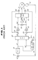
- Fig. 1 shows a vector control apparatus of the control-current-source (CCS) type which converts the motor-flux and motor-torque command current signals i1 ⁇ * and i1 ⁇ * to three-phase excitation current command signals ia*, ib* and ic* and utilizes excitation current feedback signals to ensure that the excitation currents ia, ib and ic are correct to coincide with the respective excitation current command signals ia*, ib* and ic*.
- CCS control-current-source
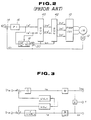
- FIG. 2 shows a vector control apparatus of the control-voltage-source (CVS) type which calculates values for excitation voltage command signals va*, vb* and vc* as a function of the motor-flux and motor-torque command current signals i1 ⁇ * and i1 ⁇ * and utilizes the calculated values to produce excitation currents ia, ib and ic as required by the motor-flux and motor-torque command current signals i1 ⁇ * and i1 ⁇ *.
- CVS control-voltage-source
- the conventional CCS type vector control apparatus includes a speed sensor 12, such as a tachometer generator, for sensing the actual angular velocity of the rotor of the motor IM.
- the speed sensor 12 produces an actual speed signal wr indicative of the sensed value of the angular velocity of the rotor of the motor IM.
- the actual speed signal wr is applied to a subtractor 14 having another input from a current source which produces a speed command signal wr* indicative of a required value for motor speed.
- the subtractor 14 subtracts signal wr* to provide a speed error signal indicative of the difference between the actual-speed and speed-command signals wr and wr*.
- the speed error signal is fed from the subtractor 14 to a proportional-plus-integral control circuit 16 which converts it into a motor-torque command current signal i1 ⁇ * indicative of a required value for motor torque expressed in the rotating coordinate system.
- the motor-torque command current signal i1 ⁇ * is fed to a slip calculation circuit 18 having another input from a current source which produces a motor-flux command current signal i1 ⁇ * indicative of a required value for motor flux expressed in the rotating coordinate system.
- the slip calculation circuit 18 produces a slip frequency signal ws indicative of the calculated slip frequency value.
- the slip frequency signal ws is fed to a summing circuit 20 which adds it to the actual speed signal wr fed thereto from the speed sensor 12 and produces an angular frequency signal wo indicative of a primary angular frequency.
- the angular frequency signal wo is applied to a coordinate converter 22 which also receives the motor-torque command current signal i1 ⁇ * and the motor-flux command current signal i1 ⁇ *.
- the coordinate converter 22 utilizes the angular frequency signal wo for converting the motor-flux and motor-torque command current signals i1 ⁇ * and i1 ⁇ * to two-phase exitation current command signals ia* and ic*.
- the excitation current command signal ia* is applied to a subtractor 24 having another input from a current transformer 36.
- the current transformer 36 is coupled to one of the output conductors for providing an excitation current feedback signal.
- the subtractor 24 subtracts the excitation current feedback signal from the excitation current command signal ia* to produce an error signal.
- This error signal is applied to the PWM/INV unit 10 through a proportional-plus-integral control circuit 28 which converts the error signal into an excitation voltage command signal va*.
- the excitation current command signal ic* is applied to a subtractor 26 having another input from a current transformer 38.
- the current transformer 38 is coupled to another output conductor for providing an excitation current feedback signal.
- the subtractor 26 subtracts the excitation current feedback signal from the excitation current command signal ic* to produce an error signal.
- This error signal is applied to the PWM/INV unit 10 through a proportional-plus-integral control circuit 30 which converts the error signal into an excitation voltage command signal vc*.
- the excitation voltage command signals va* and vc* are also applied to a summing circuit 32 which adds them and produces an added signal. This added signal is applied to an inverting amplifier 34 which inverts the input signal into an excitation voltage command signal vb*.
- the excitation voltage command signal vb* is applied to the PWM/INV unit 10.
- the PWM/INV unit 10 which receives the excitation voltage command signals va*, vb* and vc*, varies the power to the induction motor IM.
- the excitation current feedback signals are used to ensure the excitation currents ia, ib and ic are correct to coincide with the respective excitation current command signals ia*, ib* and ic* so as to maintain a 90° phase difference between the motor-flux and motor-torque command current signals i1 ⁇ * and i1 ⁇ *.
- the conventional CVS type vector control apparatus includes a speed sensor 12, such as a tachometer generator, for sensing the actual angular velocity of the rotor of the motor IM.
- the speed sensor 12 produces an actual speed signal wr indicative of the sensed value of the angular velocity of the rotor of the motor IM.
- the actual speed signal wr is applied to a subtractor 14 having another input from a current source which produces a speed command signal wr* indicative of a required value for motor speed.
- the subtractor 14 subtracts the actual speed signal wr from the speed command signal wr* to provide a speed error signal indicative of the difference between the actual-speed and speed-command signals wr and wr*.
- the speed error signal is fed from the subtractor 14 to a proportional-plus-integral control circuit 16 which converts the speed error signal to a motor-torque command current signal i1 ⁇ * indicative of a required value for motor torque expressed in the rotating coordinate system.
- the motor-torque command current signal i1 ⁇ * is fed to a slip calculation circuit 18 having another input from a current source which produces a motor-flux command current signal i1 ⁇ * indicative of a required value for motor flux expressed in the rotating coordinate system.
- the slip calculation circuit 18 produces a slip frequency signal ws indicative of the calculated slip frequency value.
- the slip frequency signal ws is fed to a summing circuit 20 which adds it to the actual speed signal wr fed thereto from the speed sensor 12 and produces an angular frequency signal wo indicative of a primary angular frequency.
- the angular frequency signal wo is applied to a non-interference calculation circuit 40 and also to a coordinate converter 42.
- the non-interference calculation circuit 40 calculates the required values for the motor-flux and motor-torque command voltage signals v1 ⁇ * and v1 ⁇ * in a manner to cancel the interference component wo x L ⁇ between the current signals i1 ⁇ and i1 ⁇ and the interference component wo x L1 between the voltage signals v1 ⁇ and v1 ⁇ .
- the motor-flux and motor-torque command voltage signals v1 ⁇ * and v1 ⁇ * are applied to the coordinate converter 42 which utilizes the angular frequency signal wo for converting the motor-flux and motor-torque command voltage signals v1 ⁇ * and v1 ⁇ * to three-phase excitation voltage command signals va*, vb* and vc*.
- the three-phase excitation voltage command signals va*, vb* and vc* are applied to the PWM/INV unit 10 which thereby varies the power to the induction motor IM according to the excitation voltage command signals.
- An induction motor voltage equation expressed in a two-dimentional coordinate system (d, q) fixed with respect to the stator of the induction motor is given as: where vid is the d-axis primary voltage, v1q is the q-axis primary voltage, i1d is the d-axis primary current, i1q is the q-axis primary current, ⁇ 2d is the d-axis secondary flux, ⁇ 2q is the q-axis secondary flux, wr is the angular velocity of the rotor of the motor, P is the differentiating operator, r1 is the primary resistance, r2 is the secondary resistance, L1 is the primary inductance, L2 is the secondary inductance, M is the excitation inductance, and L ⁇ is the equivalent inductance.
- Equation (4) can be modified into Equation (5) expressed in another two-dimentional coordinate system ( ⁇ , ⁇ ) rotating at the same angular velocity as the angular velocity wo of the rotor of the induction motor as: where v1 ⁇ is the ⁇ -axis primary voltage, v1 ⁇ is the ⁇ -axis primary voltage, i1 ⁇ is the ⁇ -axis primary current, i1 ⁇ is the ⁇ -axis primary current, ⁇ 2 ⁇ is the ⁇ -axis secondary flux, and ⁇ 2 ⁇ is the ⁇ -axis secondary flux.
- the conventional vector control apparatus In order to satisfy the two conditions for induction motor vector control, the conventional vector control apparatus require a suitable means for measuring the angular velocity wr of the rotor of the induction motor in order to satisfy the conditions for vector control.
- the estimated value wx for the angular velocity of the rotor of the induction motor is used to satisfy Equations (6) and (7). The principle of the invention will be described greater detail.
- Equations (10), (11) and (12) the ⁇ -axis secondary flux is determined by the d-axis primary voltage v1d, the q-axis primary voltage v1q, the d-axis primary current i1d, and the q-axis primary current. Accordingly, the angular velocity wr of the rotor of the induction motor can be estimated from the primary current and voltage without the use of any means for sensing the rotor angular velocity wr. In order to provide accurate vector control according to the invention, it is preferable that the secondary flux ⁇ 2 be maintained constant. The reason for this will be described in connection with Figs. 4 and 5.
- Fig. 4 contains three graphs showing motor characteristics provided when the motor is operating under the CVS type vector control. These graphs are obtained by varying the second resistance r2 while maintaining the motor-flux and motor-torque command current signals i1 ⁇ * and i1 ⁇ * constant. As can be seen by a study of Fig. 4, the secondary flux
- Fig. 5 contains three graphs showing motor characteristics provided when the motor is operating under the CCS type vector control. These graphs are obtained by varying the second resistance while maintaining the motor-flux and motor-torque command current signals i1 ⁇ * and i1 ⁇ constant. As can be seen by the reference to Fig. 5, the secondary flux
- the vector control apparatus includes an angular velocity estimation circuit, generally designated by the numeral 50, for estimating the angular velocity of the rotor of the induction motor IM.
- the estimation circuit 50 produces an estimated speed signal wr indicative of an estimated value of the angular velocity wr.
- the estimated speed signal wr is applied to a subtractor 14 having another input from a current source which produces a speed command signal wr* indicative of a required value for motor speed.
- the subtractor 14 subtracts the estimated speed signal wr from the speed command signal wr* to provide a speed error signal indicative of the difference between the estimated-speed and speed-command signals wr and wr*.
- the speed error signal is fed from the subtractor 14 to a proportional-plus-integral control circuit 16 which converts the speed error signal to a motor-torque command current signal i1 ⁇ * indicative of a required value for motor torque expressed in the rotating coordinate system.
- the motor-torque command current signal i1 ⁇ * is fed to a slip calculation circuit 18 having another input from a current source which produces a motor-flux command current signal i1 ⁇ * indicative of a required value for motor flux expressed in the rotating coordinate system.
- the slip calculation circuit 18 produces a slip frequency signal ws indicative of the calculated slip frequency value.
- the slip frequency signal ws is fed to a summing circuit 20 which adds it to the estimated speed signal wr fed thereto from the angular velocity estimation circuit 50 and produces an angular frequency signal wo indicative of a primary angular frequency.
- the angular frequency signal wo is applied to an integrating circuit 60 which integrates the angular frequency signal wo to produce an estimated angular position signal ⁇ indicative of the estimated value of the angular position of the secondary flux.
- the angular frequency signal wo is also applied to a non-interference calculation circuit 40.
- the non-interference calculation circuit 40 converts the motor-flux and motor-torque command current signals i1 ⁇ * and i1 ⁇ * to motor-flux and motor-torque command voltage signals v1 ⁇ * and v1 ⁇ * by calculating required values for the voltage signals v1 ⁇ * and v1 ⁇ * from Equations (1) and (3).
- the non-interference calculation circuit 40 calculates the motor-flux and motor-torque command voltage signals v1 ⁇ * and v1 ⁇ * in a manner to cancel the interference component wo x L ⁇ between the current signals i1 ⁇ and i1 ⁇ and the interference component wo x L1 between the voltage signals v1 ⁇ and v1 ⁇ .
- the motor-flux and motor-torque command voltage signals v1 ⁇ * and v1 ⁇ * are applied to a converter 70 which utilizes the angular position signal ⁇ for converting the motor-flux and motor-torque command voltage signals v1 ⁇ * and v1 ⁇ * to three-phase excitation voltage command signals va*, vb* and vc*.
- the converter 70 includes a coordinate converter 71 and a 2-phase/3-phase converter 72.
- the converted command voltage signals v1d* and v1q* are applied to the 2-phase/3-phase converter 72 which converts them to three-phase excitation voltage command signals va*, vb* and vc*.
- the excitation voltage command signals va*, vb* and vc* are applied to a PWM/INV unit 10 which varies the power to the induction motor IM according to these inputs.
- the angular velocity estimation circuit 50 includes a converter 51 having inputs from two current transformers.
- the first current transformer is coupled to one of the three-phase output conductors for providing an excitation current feedback signal indicative of the a-phase excitation current ia.
- the second current transformer is coupled to another output conductor for providing an excitation current feedback signal indicative of the c-phase excitation current ic.
- the converter 51 measures the b-phase excitation current ib based on these excitation current feedback signals and produces primary current signals i1d and i1q indicative of the d- and q-axis primary current values expressed in the fixed coordinate system (d, q).
- the converter 51 calculates the d- and q-axis primary current values from the following equation:
- the primary current signals i1d and i1q are fed to a secondary flux calculation circuit 52.
- This calculation circuit also receives the command voltage signals v1d* and v1q* from the coordinate converter 71.
- the command voltage signals v1d* and v1q* are used in place of measurements of the actual primary voltage values since the PWM/INV unit 10 has a property of producing sine wave output voltages correctly as commanded by the command voltage signals v1d* and v1q*.
- the secondary flux calculation circuit 52 estimates d- and q-axis secondary flux values ⁇ 2d and ⁇ 2q from Equation (10) and (11) and produces estimated secondary flux signals ⁇ 2d and ⁇ 2q indicative of the estimated d- and q-axis secondary flux values to a coordinate converter 53.
- the coordinate converter 53 utilizes the angular position signal ⁇ to convert the estimated secondary flux signals ⁇ 2d and ⁇ 2q to estimated secondary flux signals ⁇ 2 ⁇ and ⁇ 2 ⁇ expressed in the rotating coordinate system ( ⁇ , ⁇ ). This conversion is made according to Equation (12).
- the estimated secondary flux signal ⁇ 2 ⁇ indicative of the estimated ⁇ -axis secondary flux is applied to a calculation circuit generally designated by the numeral 54.
- the calculation circuit 54 calculates an estimated value wr for the angular velocity wr of the rotor of the induction motor IM. This calculation is made as a function of estimated ⁇ -axis secondary flux ⁇ 2 ⁇ from Equation (9).
- the calculation circuit 54 includes a proportional amplifier 55 and an integrating amplifier 56.
- the proportional amplifier 55 recives the estimates ⁇ -axis secondary flux signal ⁇ 2 ⁇ and produces an output siganl having a magnitude (ki x ⁇ 2 ⁇ ) proportional to the magnitude of the estimated ⁇ -axis secondary flux signal ⁇ 2 ⁇ .
- the integrating amplifier 56 receives the estimated ⁇ -axis secondary flux signal ⁇ 2 ⁇ and produces an output signal having a magnitude (Km x ⁇ 2 ⁇ ) proportional to the integral of the magnitude of the estimated ⁇ -axis secondary flux signal ⁇ 2 ⁇ .
- the signals outputted from the amplifying circuits 55 and 56 are fed to a summing circuit 57 where they are added to produce the estimated speed signal wr indicative of the estimated angular velocity of the rotor of the induction motor IM.
- an actual value for induction motor angular velocity is estimated as a function of primary current and voltage applied to drive the induction motor. It is, therefore, possible to eliminate the need for a tachometer generator or other speed sensors used in measuring the existing induction motor angular velocity.
Landscapes
- Engineering & Computer Science (AREA)
- Power Engineering (AREA)
- Control Of Ac Motors In General (AREA)
Claims (12)
- Ein Verfahren für eine Vektorsteuerung eines Induktionsmotors (IM) einstellbarer Geschwindigkeit mit einem sekundären Widerstand r2, einer sekundären Induktivität L2 und einer sekundären Zeitkonstante t2, die im allgemeinen gleich dem sekundären Widerstand r2 dividiert durch die sekundäre Induktivität L2 ist, und mit Mitteln zum Anlegen eines primären Stroms und einer primären Spannung ia, ib, ic; va*, vb* vc*, um den Induktionsmotor (IM) anzutreiben,
welches die Schritte einschließt, daß:
ein gewünschtes Motordrehmoment i1β* eingestellt wird, ein gewünschter Motorfluß i1α* eingestellt wird;
der primäre Strom und die primäre Spannung ia, ib, ic; va*, vb*, vc* wahrgenommen werden;
eine Schlupffrequenz ws* berechnet wird, die auf das gewünschte Motordrehmoment i1β*, den gewünschten Motorfluß i1α* und die sekundäre Zeitkonstante t2 gestützt ist, die berechnete Schlupffrequenz ws* zu einem Induktionsmotorwinkelgeschwindigkeitswert
die Motorantriebsmittel gesteuert werden, gestützt auf das gewünschte Motordrehmoment i1β*, den gewünschten Motorfluß i1α* und die berechnete Winkelfrequenz wo, um den primären Strom und die primäre Spannung ia, ib, ic; va*, vb*, vc* zu variieren und somit den Induktionsmotor (IM) mit keinem sekundären β-Achsen-Fluß anzutreiben, wobei das Verfahren durch den Schritt gekennzeichnet ist, daß:
der Induktionsmotorwinkelgeschwindigkeitswertwr als eine Funktion des wahrgenommenen primären Stroms und der wahrgenommenen primären Spannung ia, ib, ic; va*, vb*, vc* abgeschätzt wird, wobei die Abschätzung bestimmt ist durch

worin ki und km konstant sind und λ2β der sekundäre β-Achsen-Fluß ist, der lediglich von ia, ib, ic; va*, vb*, vc* abhängt. - Das Verfahren wie in Anspruch 1 beansprucht,
worin der Winkelgeschwindigkeitsabschätzungsschritt die Schritte einschließt, daß ein Wert λ2β für den sekundären β-Achsen-Fluß als eine Funktion des primären Stroms und der primären Spannung abgeschätzt wird und der abgeschätzte Winkelgeschwindigkeitswert wx berechnet wird gemäß:

wobei ki und km Konstanten sind. - Das Verfahren wie in Anspruch 2 beansprucht,
worin der Einstellschritt für das gewünschte Motordrehmoment die Schritte einschließt, daß ein gewünschter Motorwinkelgeschwindigkeitswert eingestellt wird, ein Fehler zwischen den gewünschten und abgeschätzten Motorwinkelgeschwindigkeitswerten berechnet wird und ein gewünschter Wert für das Motordrehmoment als eine Funktion des berechneten Fehlers berechnet wird. - Das Verfahren wie in Anspruch 2 beansprucht,
worin der Induktionsmotor (IM) einen primären Widerstand r1, eine primäre Induktivität L1 und eine äquivalente Streuinduktivität Lσ aufweist und worin die Schritte des Steuerns der Motorantriebsmittel die Schritte einschließen, daß:
Werte v1α* und v1β* für Motorfluß- und Motordrehmomentbefehlsspannungen berechnet werden gemäß:


wobei i1α* der gewünschte Motorfluß, i1β* das gewünschte Motordrehmoment und wo die berechnete Winkelfrequenz ist; und die berechneten Werte v1α* und v1β* in 3-Phasen-Erregerspannungen va*, vb*, vc* umgewandelt werden, um den Induktionsmotor (IM) anzutreiben. - Das Verfahren wie in Anspruch 4 beansprucht,
worin der Schritt des Umwandelns der berechneten Werte v1α* und v1β* die Schritte einschließt, daß: die berechneten Werte v1α* und v1β* in Motorfluß- und Motordrehmomentbefehlsspannungswerte v1d* und v1q* umgewandelt werden und die berechneten Werte v1d* und v1q* in 3-Phasen-Erregerspannungen umgewandelt werden. - Das Verfahren wie in Anspruch 5 beansprucht,
worin der Induktionsmotor eine Erregerinduktivität M und eine sekundäre Induktivität L2 aufweist und worin der Schritt des Berechnens des abgeschätzten Winkelgeschwindigkeitswerts wx die Schritte einschließt, daß: primäre d- und q-Achsen-Stromwerte i1d und i1q als eine Funktion primärer Ströme zum Induktionsmotor berechnet werden; sekundäre p- und q-Achsen-Flußwerte λ2d und λ2q berechnet werden gemäß:


und die berechneten Werte λ2d und λ2q in den sekundären β-Achsen-Flußwert λ2β unter Verwendung der berechneten Winkelfrequenz umgewandelt werden. - Ein Gerät für eine Vektorsteuerung eines Induktionsmotors (IM) einstellbarer Geschwindigkeit mit einem sekundären Widerstand r2, einer sekundären Induktivität L2 und einer sekundären Zeitkonstante t2, die im allgemeinen gleich dem sekundären Widerstand r2 dividiert durch die sekundäre Induktivität L2 ist, und mit Mitteln zum Anlegen eines primären Stroms und einer primären Spannung ia, ib, ic; va*, vb* vc*, um den Induktionsmotor (IM) anzutreiben, einer ersten Quelle zum Erzeugen eines Drehmomentbefehlssignals i1β*, das ein gewünschtes Motordrehmoment anzeigt, einer zweiten Quelle zum Erzeugen eines Flußbefehlssignals i1α*, das einen gewünschten Motorfluß anzeigt, Sensormitteln zum Wahrnehmen des primären Stroms und der primären Spannung ia, ib, ic; va*, vb*, vc*; Mitteln (18) zum Berechnen einer Schlupffrequenz, gestützt auf das Drehmomentbefehlssignals i1β*, das Flußbefehlssignal i1α* und die sekundäre Zeitkonstante t2, um ein Schlupffrequenzsignal ws* zu erzeugen, das die berechnete Schlupffrequenz anzeigt, Mitteln (20) zum Addieren des berechneten Schlupffrequenzsignals ws* zu einem Geschwindigkeitssignal

Mittel (50), die an die Sensormittel gekoppelt sind, um einen Wert für eine Induktionsmotorwinkelgeschwindigkeit als eine Funktion des wahrgenommenen primären Stroms und der wahrgenommenen primären Spannung ia, ib, ic; va*, vb*, vc* abzuschätzen und somit das Geschwindigkeitssignalwr zu erzeugen, das die abgeschätzte Motorwinkelgeschwindigkeit anzeigt, wobei wr gegeben ist durch:

worin ki und km konstant sind und λ2β der sekundäre β-Achsen-Fluß ist, der lediglich von ia, ib, ic; va*, vb*, vc* abhängt. - Das Gerät wie Anspruch 7 beansprucht,
worin die Winkelgeschwindigkeitsabschätzungsmittel einen Schaltkreis zum Abschätzen eines Werts λ2β für den sekundären β-Achsen-Fluß als eine Funktion des primären Stroms und der primären Spannung und Mittel einschließen, welche den abgeschätzten Winkelgeschwindigkeitswert wx berechnen gemäß:

wobei ki und km Konstanten sind. - Das Gerät wie in Anspruch 8 beansprucht,
worin die erste Quelle Mittel zum Erzeugen eines Geschwindigkeitsbefehlssignals, das eine gewünschte Motorgeschwindigkeit anzeigt, Mittel zum Berechnen einer Differenz zwischen dem Geschwindigkeitsbefehlssignal und dem abgeschätzten Geschwindigkeitssignal, um ein Geschwindigkeitsfehlersignal zu erzeugen, das die berechnete Differenz anzeigt, und einen Proportional-plus-Integral-Schaltkreis einschließt, der das Geschwindigkeitsfehlersignal empfängt, um das Geschwindigkeitsfehlersignal in das Drehmomentbefehlssignal umzuwandeln. - Das Gerät wie in Anspruch 8 beansprucht,
worin der Induktionsmotor (IM) einen primären Widerstand r1, eine primäre Induktivität L1 und eine äquivalente Streuinduktivität Lσ aufweist und worin der Steuerungsschaltkreis (40, 70, 10) Mittel (40), die Werte v1α* und v1β* für Motorfluß- und Motordrehmomentbefehlsspannungen berechnen gemäß:


wobei i1α* der gewünschte Motorfluß, i1β* das gewünschte Motordrehmoment und wo die berechnete Winkelfrequenz ist, und Mittel (70) einschließt, welche die berechneten Werte v1α* und v1β* in 3-Phasen-Erregerspannungen va*, vb*, vc* umwandeln, um den Induktionsmotor (IM) anzutreiben. - Das Gerät wie in Anspruch 10 beansprucht,
worin das Mittel zum Umwandeln der berechneten Werte v1α* und v1β* Mittel zum Umwandeln der berechneten Werte v1α* und v1β* in Motorfluß- und Motordrehmomentbefehlsspannungswerte v1d* und v1q* und Mittel zum Umwandeln der berechneten Werte v1d* und v1q* in 3-Phasen-Erregerspannungen einschließt. - Das Gerät wie in Anspruch 11 beansprucht,
worin der Induktionsmotor eine Erregerinduktivität M und eine sekundäre Induktivität L2 aufweist und worin das Mittel zum Berechnen des abgeschätzten Winkelgeschwindigkeitswerts wx Mittel zum Berechnen von primären d- und q-Achsen-Stromwerten i1d und i1q als eine Funktion primärer Ströme zum Induktionsmotor, Mittel zum Berechnen sekundärer p- und q-Achsen-Flußwerte λ2d und λ2q gemäß:


und Mittel einschließt, die auf das Winkelfrequenzsignal ansprechen, um die berechneten Werte λ2d und λ2q in den sekundären β-Achsen-Flußwert λ2β umzuwandeln.
Applications Claiming Priority (2)
| Application Number | Priority Date | Filing Date | Title |
|---|---|---|---|
| JP63039811A JP2780263B2 (ja) | 1988-02-23 | 1988-02-23 | 誘導電動機のベクトル制御方法と装置 |
| JP39811/88 | 1988-02-23 |
Publications (2)
| Publication Number | Publication Date |
|---|---|
| EP0330188A1 EP0330188A1 (de) | 1989-08-30 |
| EP0330188B1 true EP0330188B1 (de) | 1994-05-04 |
Family
ID=12563351
Family Applications (1)
| Application Number | Title | Priority Date | Filing Date |
|---|---|---|---|
| EP89103110A Expired - Lifetime EP0330188B1 (de) | 1988-02-23 | 1989-02-22 | Flussvektorregelung für einen Asynchronmotor |
Country Status (6)
| Country | Link |
|---|---|
| US (1) | US4967135A (de) |
| EP (1) | EP0330188B1 (de) |
| JP (1) | JP2780263B2 (de) |
| KR (1) | KR960003009B1 (de) |
| DE (1) | DE68915029T2 (de) |
| ES (1) | ES2056131T3 (de) |
Families Citing this family (38)
| Publication number | Priority date | Publication date | Assignee | Title |
|---|---|---|---|---|
| US5347206A (en) * | 1989-07-04 | 1994-09-13 | Otis Elevator Company | Vector control method of induction motor |
| JPH0755080B2 (ja) * | 1989-09-29 | 1995-06-07 | 譲 常広 | インバータの制御装置 |
| FR2665589B1 (fr) * | 1990-08-01 | 1992-10-09 | Alsthom Gec | Procede et dispositif d'estimation de flux d'induction magnetique d'un moteur asynchrone, en vue notamment de la commande de ce moteur par regulation de flux. |
| US5136228A (en) * | 1990-12-11 | 1992-08-04 | Kabushiki Kaisha Meidensha | Induction motor vector control |
| US5266787A (en) * | 1991-01-11 | 1993-11-30 | Symbol Technologies, Inc. | Laser scanner using two scan motors independently controlled by a single signal |
| JPH0583976A (ja) * | 1991-09-18 | 1993-04-02 | Hitachi Ltd | 交流電動機制御装置及びこれを用いた電気車の制御装置 |
| KR950010191B1 (ko) * | 1991-09-18 | 1995-09-11 | 삼성전자주식회사 | 유도전동기의 회전자저항 추정장치 |
| GB2261966B (en) * | 1991-11-30 | 1995-11-08 | Toshiba Kk | Driving control apparatus for induction motor |
| US5287051A (en) * | 1992-02-14 | 1994-02-15 | General Electric Company | Method and apparatus for improved efficiency in a pulse-width-modulated alternating current motor drive |
| JPH05292753A (ja) * | 1992-04-10 | 1993-11-05 | Meidensha Corp | Pwmインバータの電流検出方法 |
| EP0608571B1 (de) * | 1993-01-11 | 1998-03-25 | Kabushiki Kaisha Meidensha | Vektorkontrollsystem für Induktionsmotor |
| US5498945A (en) * | 1994-04-08 | 1996-03-12 | Ford Motor Company | Peak-torque-per-ampere (PTPA) control method for an induction motor |
| US5844397A (en) * | 1994-04-29 | 1998-12-01 | Reda Pump | Downhole pumping system with variable speed pulse width modulated inverter coupled to electrical motor via non-gap transformer |
| US5670854A (en) * | 1994-12-14 | 1997-09-23 | Matsushita Electric Industrial Co., Ltd. | Control system for an induction motor |
| JP3501559B2 (ja) * | 1995-06-27 | 2004-03-02 | キヤノン株式会社 | リニア・モータ装置 |
| FR2743456B1 (fr) * | 1996-01-04 | 1998-02-06 | Thomson Csf | Moteur electrique de type synchrone a aimants permanents et vehicule comportant un tel moteur |
| US5880572A (en) * | 1996-04-18 | 1999-03-09 | Fuji Electric Co., Ltd. | Variable-speed control method and apparatus for AC motor |
| DE19724946B4 (de) * | 1997-06-12 | 2005-09-15 | Siemens Ag | Verfahren und Vorrichtung zur Drehzahlregelung einer geberlosen, feldorientiert betriebenen Asynchronmaschine |
| US6124697A (en) * | 1997-08-20 | 2000-09-26 | Wilkerson; Alan W. | AC inverter drive |
| US5969498A (en) * | 1997-11-19 | 1999-10-19 | Unitrode Corporation | Induction motor controller |
| US6605919B1 (en) * | 1999-12-13 | 2003-08-12 | A.O. Smith Corporation | Method and apparatus for indirectly measuring induction motor slip to establish speed control |
| CA2327579C (en) * | 1999-12-13 | 2008-07-29 | A.O. Smith Corporation | Method and apparatus of improving the efficiency of an induction motor |
| US6433504B1 (en) * | 1999-12-13 | 2002-08-13 | A. O. Smith Corporation | Method and apparatus of improving the efficiency of an induction motor |
| JP3661572B2 (ja) * | 2000-07-18 | 2005-06-15 | 日産自動車株式会社 | インバーターの電流センサー診断装置 |
| JP4674942B2 (ja) * | 2000-09-08 | 2011-04-20 | ローム株式会社 | ブラシレスモータ用駆動制御装置 |
| CN100471032C (zh) * | 2000-11-20 | 2009-03-18 | 三菱电机株式会社 | 感应电动机的控制装置 |
| JP3690338B2 (ja) * | 2001-11-16 | 2005-08-31 | 松下電器産業株式会社 | モータ制御装置 |
| US6646412B2 (en) * | 2002-02-11 | 2003-11-11 | Ford Global Technologies, Llc | Method and system for controlling torque in a powertrain that includes an induction motor |
| JP3678276B2 (ja) * | 2002-08-22 | 2005-08-03 | 株式会社安川電機 | フルクローズド制御装置 |
| US6768284B2 (en) * | 2002-09-30 | 2004-07-27 | Eaton Corporation | Method and compensation modulator for dynamically controlling induction machine regenerating energy flow and direct current bus voltage for an adjustable frequency drive system |
| US6856115B2 (en) * | 2002-10-31 | 2005-02-15 | A. O. Smith Corporation | Method of and apparatus for controlling the operation of an induction motor using a model of the induction motor |
| JP3955287B2 (ja) * | 2003-04-03 | 2007-08-08 | 松下電器産業株式会社 | モータ駆動用インバータ制御装置および空気調和機 |
| WO2008065978A1 (fr) * | 2006-11-28 | 2008-06-05 | Kabushiki Kaisha Yaskawa Denki | Dispositif de commande de moteur à induction et son procédé de commande |
| US9300131B2 (en) * | 2009-06-01 | 2016-03-29 | Abb Research Ltd. | Internal electrification scheme for power generation plants |
| US9130497B2 (en) * | 2011-11-17 | 2015-09-08 | Mitsubishi Electric Corporation | Control device for alternating current rotating machine and electric power steering device equipped with control device for alternating current rotating machine |
| US10254374B2 (en) * | 2013-07-16 | 2019-04-09 | Ford Global Technologies, Llc | Method of current sensor related torque error estimation for IPMSM e-drive system |
| EP3332467A1 (de) * | 2015-08-07 | 2018-06-13 | GE Energy Products France SNC | Hilfssystem zur speicherung und bereitstellung von elektrischer energie für mehrere verwendungen in einer stromerzeugungsanlage |
| KR102255276B1 (ko) | 2018-11-20 | 2021-05-21 | 엘에스일렉트릭(주) | 인버터 제어장치 |
Citations (1)
| Publication number | Priority date | Publication date | Assignee | Title |
|---|---|---|---|---|
| EP0105511B1 (de) * | 1982-10-04 | 1988-01-13 | Hitachi, Ltd. | Verfahren zum Steuern von Induktionsmotoren |
Family Cites Families (14)
| Publication number | Priority date | Publication date | Assignee | Title |
|---|---|---|---|---|
| JPS5953796B2 (ja) * | 1978-03-14 | 1984-12-26 | 株式会社東芝 | 誘導電動機の制御装置 |
| DE3212439C2 (de) * | 1982-04-02 | 1992-02-20 | Robert Prof.Dr.-Ing. 6100 Darmstadt Jötten | Verfahren zum Betrieb einer durch schnelle elektrische Stellglieder gespeisten Asynchronmaschine |
| DE3221906A1 (de) * | 1982-06-08 | 1983-12-15 | Licentia Patent-Verwaltungs-Gmbh, 6000 Frankfurt | Verfahren zur steuerung einer asynchronmaschine |
| US4509003A (en) * | 1983-03-10 | 1985-04-02 | Kabushiki Kaisha Meidensha | Vector control method and system for an induction motor |
| JPS59178995A (ja) * | 1983-03-28 | 1984-10-11 | Meidensha Electric Mfg Co Ltd | ベクトル制御用関数発生装置 |
| DE3460506D1 (en) * | 1983-05-27 | 1986-09-25 | Siemens Ag | Method and apparatus to derive the flux vector of an induction machine from the stator current and the stator voltage, and application thereof |
| JPS60118085A (ja) * | 1983-11-28 | 1985-06-25 | Meidensha Electric Mfg Co Ltd | 誘導電動機のベクトル制御装置 |
| DE3418573A1 (de) * | 1984-05-18 | 1985-12-05 | Siemens AG, 1000 Berlin und 8000 München | Verfahren und vorrichtung zum stabilisieren der ortskurve eines durch integration gebildeten vektors |
| JPS61196787A (ja) * | 1985-02-25 | 1986-08-30 | Fanuc Ltd | 誘導電動機のトルク制御方式 |
| JPS62107691A (ja) * | 1985-10-31 | 1987-05-19 | Mitsubishi Electric Corp | 交流電動機の速度制御装置 |
| US4724373A (en) * | 1986-02-20 | 1988-02-09 | Wisconsin Alumni Research Foundation | Method and apparatus for flux and torque sensing in electrical machines |
| JPH0797920B2 (ja) * | 1986-04-28 | 1995-10-18 | 三菱電機株式会社 | 誘導電動機制御装置 |
| JPH0828972B2 (ja) * | 1986-05-12 | 1996-03-21 | 三菱電機株式会社 | 非循環電流方式サイクロコンバ−タの制御装置 |
| DE3812314C2 (de) * | 1987-04-13 | 1994-05-11 | Hitachi Ltd | Steuerverfahren für einen Asynchronmotor |
-
1988
- 1988-02-23 JP JP63039811A patent/JP2780263B2/ja not_active Expired - Lifetime
-
1989
- 1989-02-22 US US07/314,042 patent/US4967135A/en not_active Expired - Lifetime
- 1989-02-22 ES ES89103110T patent/ES2056131T3/es not_active Expired - Lifetime
- 1989-02-22 DE DE68915029T patent/DE68915029T2/de not_active Expired - Fee Related
- 1989-02-22 EP EP89103110A patent/EP0330188B1/de not_active Expired - Lifetime
- 1989-02-23 KR KR1019890002144A patent/KR960003009B1/ko not_active Expired - Lifetime
Patent Citations (1)
| Publication number | Priority date | Publication date | Assignee | Title |
|---|---|---|---|---|
| EP0105511B1 (de) * | 1982-10-04 | 1988-01-13 | Hitachi, Ltd. | Verfahren zum Steuern von Induktionsmotoren |
Also Published As
| Publication number | Publication date |
|---|---|
| US4967135A (en) | 1990-10-30 |
| DE68915029D1 (de) | 1994-06-09 |
| JPH01214287A (ja) | 1989-08-28 |
| DE68915029T2 (de) | 1994-08-25 |
| ES2056131T3 (es) | 1994-10-01 |
| EP0330188A1 (de) | 1989-08-30 |
| JP2780263B2 (ja) | 1998-07-30 |
| KR890013871A (ko) | 1989-09-26 |
| KR960003009B1 (ko) | 1996-03-02 |
Similar Documents
| Publication | Publication Date | Title |
|---|---|---|
| EP0330188B1 (de) | Flussvektorregelung für einen Asynchronmotor | |
| KR100354775B1 (ko) | 동기 릴럭턴스 모터의 속도 제어장치 | |
| EP0279415B1 (de) | Regelgerät für Induktionsmotor | |
| EP0436138B1 (de) | Induktionsmotorregler mit Temperaturkompensation | |
| EP0082303B1 (de) | Verfahren und Vorrichtung zum Steuern eines Induktionsmotors | |
| US4958117A (en) | Frequency control based on sensing voltage fed to an induction motor | |
| EP0490024B1 (de) | Vektorsteuerung | |
| EP0233948B1 (de) | Verfahren zur regelung eines dreiphaseninduktionsmotors | |
| KR19980024023A (ko) | 회전자석형 다상동기 전동기의 제어방법 및 그 장치 | |
| EP0278987B1 (de) | Motorregelvorrichtung | |
| JP3684661B2 (ja) | 交流電動機の制御装置 | |
| JP2634959B2 (ja) | 速度センサレス速度制御方式 | |
| JP3609098B2 (ja) | 誘導電動機のベクトル制御装置におけるモータ定数同定方法 | |
| JP3309520B2 (ja) | 誘導電動機の制御方法 | |
| JP3361885B2 (ja) | 誘導電動機の制御装置 | |
| JPH0344509B2 (de) | ||
| JPH03135389A (ja) | 電圧形インバータの制御方法及びその装置 | |
| JP3124019B2 (ja) | 誘導電動機の制御装置 | |
| JPH1141999A (ja) | 誘導電動機制御装置 | |
| KR100319943B1 (ko) | 동기 전동기의 자극위치 검출장치 | |
| JP4143908B2 (ja) | 電動機制御装置 | |
| JPS6329518B2 (de) | ||
| JPH0785677B2 (ja) | 電圧形インバ−タの制御方法 | |
| JPH08224000A (ja) | 誘導電動機の制御装置 | |
| JPS6334719B2 (de) |
Legal Events
| Date | Code | Title | Description |
|---|---|---|---|
| PUAI | Public reference made under article 153(3) epc to a published international application that has entered the european phase |
Free format text: ORIGINAL CODE: 0009012 |
|
| AK | Designated contracting states |
Kind code of ref document: A1 Designated state(s): DE ES FR GB |
|
| 17P | Request for examination filed |
Effective date: 19900208 |
|
| 17Q | First examination report despatched |
Effective date: 19911203 |
|
| GRAA | (expected) grant |
Free format text: ORIGINAL CODE: 0009210 |
|
| AK | Designated contracting states |
Kind code of ref document: B1 Designated state(s): DE ES FR GB |
|
| REF | Corresponds to: |
Ref document number: 68915029 Country of ref document: DE Date of ref document: 19940609 |
|
| ET | Fr: translation filed | ||
| REG | Reference to a national code |
Ref country code: ES Ref legal event code: FG2A Ref document number: 2056131 Country of ref document: ES Kind code of ref document: T3 |
|
| PLBE | No opposition filed within time limit |
Free format text: ORIGINAL CODE: 0009261 |
|
| STAA | Information on the status of an ep patent application or granted ep patent |
Free format text: STATUS: NO OPPOSITION FILED WITHIN TIME LIMIT |
|
| 26N | No opposition filed | ||
| PGFP | Annual fee paid to national office [announced via postgrant information from national office to epo] |
Ref country code: FR Payment date: 19960116 Year of fee payment: 8 |
|
| PGFP | Annual fee paid to national office [announced via postgrant information from national office to epo] |
Ref country code: GB Payment date: 19960201 Year of fee payment: 8 |
|
| PGFP | Annual fee paid to national office [announced via postgrant information from national office to epo] |
Ref country code: ES Payment date: 19960227 Year of fee payment: 8 |
|
| PGFP | Annual fee paid to national office [announced via postgrant information from national office to epo] |
Ref country code: DE Payment date: 19960411 Year of fee payment: 8 |
|
| PG25 | Lapsed in a contracting state [announced via postgrant information from national office to epo] |
Ref country code: GB Effective date: 19970222 |
|
| PG25 | Lapsed in a contracting state [announced via postgrant information from national office to epo] |
Ref country code: ES Free format text: LAPSE BECAUSE OF NON-PAYMENT OF DUE FEES Effective date: 19970224 |
|
| GBPC | Gb: european patent ceased through non-payment of renewal fee |
Effective date: 19970222 |
|
| PG25 | Lapsed in a contracting state [announced via postgrant information from national office to epo] |
Ref country code: FR Effective date: 19971030 |
|
| PG25 | Lapsed in a contracting state [announced via postgrant information from national office to epo] |
Ref country code: DE Effective date: 19971101 |
|
| REG | Reference to a national code |
Ref country code: FR Ref legal event code: ST |
|
| REG | Reference to a national code |
Ref country code: ES Ref legal event code: FD2A Effective date: 19990405 |