EP0326684A2 - Schneckenpresse - Google Patents
Schneckenpresse Download PDFInfo
- Publication number
- EP0326684A2 EP0326684A2 EP88120509A EP88120509A EP0326684A2 EP 0326684 A2 EP0326684 A2 EP 0326684A2 EP 88120509 A EP88120509 A EP 88120509A EP 88120509 A EP88120509 A EP 88120509A EP 0326684 A2 EP0326684 A2 EP 0326684A2
- Authority
- EP
- European Patent Office
- Prior art keywords
- screw
- scraper
- wheel
- conical
- trough
- Prior art date
- Legal status (The legal status is an assumption and is not a legal conclusion. Google has not performed a legal analysis and makes no representation as to the accuracy of the status listed.)
- Granted
Links
Images
Classifications
-
- B—PERFORMING OPERATIONS; TRANSPORTING
- B30—PRESSES
- B30B—PRESSES IN GENERAL
- B30B11/00—Presses specially adapted for forming shaped articles from material in particulate or plastic state, e.g. briquetting presses, tabletting presses
- B30B11/22—Extrusion presses; Dies therefor
- B30B11/24—Extrusion presses; Dies therefor using screws or worms
- B30B11/248—Means preventing the material from turning with the screw or returning towards the feed hopper
Definitions
- the invention relates to a screw press with a screw trough and a scraper wheel, in particular with the features of the preamble of claim 1.
- the scraper wheel engages between the turns of the conical screw part of the cantilevered screw to prevent the pressed material from rotating.
- the toothing or the worm gear is exposed to great wear and the friction that occurs is significant.
- Another screw press with a cylindrical screw is provided with several scraper wheels on the underside, which engage between the screw flights and are driven in a manner derived from the main gearbox, but have a diameter the size of the screw core diameter, so that each scraper wheel engages only once in the screw flight.
- the loss of material to be pressed becomes large, as does the drive energy to be used.
- the object of the invention is to reduce or eliminate the disadvantages described in a screw press, such as high losses of pressed material, high frictional forces and thus energy losses and high wear of the scraper wheel, both with forward and backward running of the machine with little effort.
- the low speed of the scraper wheel and the covering and stripping of the same prevents the loss of pressed material, high energy losses and the wear of the scraper wheel are greatly reduced. Furthermore, the stripping on the gap walls is significantly improved by the special design of the scraper wheel on the end faces.
- the transfer of the pressed material into the open screw trough on the inlet side of the screw is significantly improved by the design of the gaps on both sides of the stripping wheel.
- the design and arrangement of the scraper wheel in such a way that it extends into the screw trough enables particularly good return of the pressed material to the input side of the screw.
- the enlargement of the diameter is favorable, but this is limited in relation to the core diameter of the screw at the point of engagement of the scraper wheel, because with increasing diameter of the scraper wheel the number of interventions in the screw increases and the scraper effect is thereby less favorable becomes;
- the length of the longitudinal gap for the scraper wheel becomes larger and thus the amount of material to be returned, so that the disadvantages of further enlargement outweigh the advantages over an upper limit of the diameter.
- it is advantageous to drive the scraper wheel synchronously with the worm whereby the play of the drive arrangement can be kept low by a worm gear, which in turn is favorable for reducing wear.
- a particularly advantageous embodiment of the housing consists of a cover, which in turn is designed as a scraper for the scraper wheel, with which the scraper wheel is stripped in the housing both when the machine runs forwards and backwards, so that the return of No material is pressed into the conical mouthpiece, which reduces friction, energy and wear.
- a one-sided screw (not shown) with its cylindrical conveying part 2 is arranged in an open-top screw trough 3, to which a conical mouthpiece 4 is attached, which is arranged in a housing 5, which in turn is fastened to the machine frame 6.
- a conical screw part 7 is arranged in the conical mouthpiece 4 and forms the conical mixing and compression part of the screw 1.
- a wiper wheel 9 engages from above through a longitudinal gap 8 of the conical mouthpiece 4 with its - indicated - toothing between the - indicated - screw flights, the shaft 10 of which has an axis 11 perpendicular to the longitudinal axis 12 of the screw 1.
- the scraper wheel 9 has an approximately five times larger diameter than the core 13 of the screw 1 at the point of engagement 14 of the scraper wheel 9, so that the number of revolutions can be kept correspondingly low.
- the scraper wheel 9 is mounted with the shaft 10 in bilateral bearings 15, 15 'in the housing 5, the side walls 16, 16' with the two end faces 18, 18 'of the scraper 9 in the direction of a through opening 17 in the machine frame 6, one each widening gap 19,19 'form, through which the space 20 in the housing 5 is connected to the space 21 of the open screw trough 3 above the screw 1.
- the two end faces 18, 18 'of the scraper wheel 9 are each provided with four recesses 22 which are arranged in a regularly distributed manner and extend radially from the hub 23 to the region of the toothing 24.
- an intermediate conveyor 25 for the material to be pressed is arranged in the space 21 of the open screw trough 3, the axis of rotation 26 of which runs parallel to the axis 12 of the screw 1 and the front end 27 of which scrapes the circumference of the scraper wheel 9.
- the housing 5 has above the scraper wheel 9 an opening 28 which can be closed with a housing cover 29 which is provided on the inside with a scraper 30 which surrounds the scraper wheel 9 over part of its circumference and at its two ends 31 and 32 Scraper wheel 9 scrapes on forward and reverse.
- the scraper wheel 9 is driven in synchronism with the drive of the worm 1 by a motor 33 of the main gear 34 of the machine via an intermediate shaft 35 and an intermediate gear 36, which is expediently designed as a worm gear, on the shaft 10.
- the stripping wheel 9 strips off most of the material to be pressed. A small part is taken through the longitudinal gap 8 into the space 20 of the housing 5 and stripped from the lower end 31 of the scraper 30 on the circumference. At the end faces 18, 18 'of the scraper wheel 9, the walls of the longitudinal gap 8 of the conical mouthpiece 4 act as a scraper.
- the recesses 22 reduce the frictional forces that occur and act in the space 20 of the housing 5 as a conveying aid for conveying the extruded material through the two widening gaps 19, 19 'and the passage opening 17 into the space 21 of the open screw trough 3 above the conveying part 2 of the Screw 1.
- the circumference of the stripping wheel 9 is stripped from the upper end 32 of the stripper 30 and from the walls of the longitudinal gap 8, and thus the backflow of the extruded material into the mixing and compression part is prevented.
- the synchronous drive of the scraper wheel 9 ensures the position of its toothing in relation to the worm gear.
Landscapes
- Engineering & Computer Science (AREA)
- Mechanical Engineering (AREA)
- Screw Conveyors (AREA)
- Materials For Medical Uses (AREA)
- Press Drives And Press Lines (AREA)
- Extrusion Moulding Of Plastics Or The Like (AREA)
- Treatment Of Sludge (AREA)
Abstract
Description
- Die Erfindung bezieht sich auf eine Schneckenpresse mit einem Schneckentrog und Abstreifrad, insbesonders mit den Merkmalen des Oberbegriffes des Anspruches 1.
- Bei Vorrichtungen dieser Art greift das Abstreifrad zwischen die Windungen des konischen Schneckenteiles der fliegend gelagerten Schnecke um das Mitdrehen des Preßgutes zu verhindern. Dabei ist die Verzahnung, bzw. der Schneckengang großem Verschleiß ausgesetzt und die auftretende Reibung ist bedeutend.
- Eine solche bekannte Schneckenpresse weist zur Verringerung der Reibungskräfte eine Freistellung der Verzahnung auf der Seite des Abstreifrades auf, an der die Schnecke abläuft. Die auftretenden Verluste an Preßgut durch den Längsspalt in dem Pressenmundstück und die damit verbundenen Verluste können aber nicht beeinflußt werden.
- Eine weitere Schneckenpresse mit zylindrischer Schnecke ist mit mehreren Abstreifrädern an der Unterseite versehen, die zwischen die Schneckengänge greifen und vom Hauptgetriebe abgeleitet angetrieben sind, jedoch einen Durchmesser in der Größe des Schneckenkerndurchmessers aufweisen, sodaß jedes Abstreifrad nur einmal in den Schneckengang greift. Bei hohem Verdichtungsdruck werden dadurch die Austrittsverluste an Preßgut groß, ebenso wie die aufzuwendende Antriebsenergie.
- Aufgabe der Erfindung ist es bei einer Schneckenpresse die beschriebenen Nachteile wie hohe Preßgutverluste, hohe Reibungskräfte und damit Energieverluste und hoher Verschleiß des Abstreifrades, sowohl bei Vorwärts- als auch bei Rückwärtslauf der Maschine mit geringem Aufwand zu vermindern oder zu beseitigen.
- Diese Aufgabe wird bei einer Schneckenpresse der eingangs genannten Art durch die Merkmale des Anspruches 1 gelöst.
- Für besonders vorteilhafte Ausgestaltungen wird auf die Unteransprüche 2 bis 8 verwiesen.
- Durch Verbindung der angegebenen Maßnahmen wird durch geringe Drehzahl des Abstreifrades und der Abdeckung und Abstreifung desselben, sowie durch Schaffung einer Durchtrittsöffnung in den Schneckentrog der Verlust an Preßgut vermieden, hohe Energieverluste und der Verschleiß des Abstreifrades werden stark herabgesetzt. Weiters wird durch die besondere Ausgestaltung des Abstreifrades an den Stirnseiten die Abstreifung an den Spaltwänden wesentlich verbessert.
- Die Überführung des Preßgutes in den offenen Schneckentrog an der Eingangsseite der Schnecke wird durch die Ausgestaltung der Spalte beiderseits des Abstreifrades wesentlich verbessert.
- Die Gestaltung und Anordnung des Abstreifrades derart, daß es bis in den Schneckentrog reicht, ermöglicht eine besonders gute Rückführung des Preßgutes auf die Eingangsseite der Schnecke. Für die Wahl des Durchmessers des Abstreifrades ist zwar die Vergrößerung des Durchmessers günstig, doch ist dieser in Bezug zum Kerndurchmesser der Schnecke an der Eingriffstelle des Abstreifrades begrenzt, weil mit zunehmendem Durchmesser des Abstreifrades die Zahl der Eingriffe in die Schnecke zunimmt und die Abstreifwirkung dadurch ungünstiger wird; ebenso wird die Länge des Längsspaltes für das Abstreifrad größer und damit die Menge der Preßgutrückführung, so daß über eine Obergrenze des Durchmessers die Nachteile einer weiteren Vergrößerung die Vorteile aufwiegen.
Zur Herabsetzung des Verschleißes ist es von Vorteil das Abstreifrad synchron mit der Schnecke anzutreiben, wodurch durch ein Schneckengetriebe das Spiel der Antriebsanordnung gering gehalten werden kann, was wiederum für die Herabsetzung des Verschleißes günstig ist. - Die Anordnung des Abstreifrades im Bereich des offenen Schneckentroges so, daß ein dort vorgesehener Zwischenförderer für die Beschickung der Schnecke an dieses heranreicht und als Abstreifer wirkt, vermeidet das Wiederzurückführen von Preßgut in den Gehäusebereich hinter den Längsspalt des konischen Mundstückes und dient damit in vorteilhafter Weise der Herabsetzung der Reibungskräfte und des Energieverbrauches, sowie des Verschleißes, sowohle bei Vorwärts-als auch bei Rückwärtslauf der Maschine.
- Eine besonders vorteilhafte Ausgestaltung des Gehäuses besteht in einem Deckel, der seinerseits als Abstreifer für das Abstreifrad gestaltet ist, mit dem das Abstreifrad sowohl bei Vorwärts- als auch bei Rückwärtslauf der Maschine im Gehäuse abgestreift wird, sodaß die Rückführung von Preßgut in das konische Mundstück unterbleibt, wodurch Reibungskraft, Energie und Verschleiß verringert werden.
- Eine Ausführungsform der Erfindung ist an Hand der Zeichnung nachstehend beschrieben.
- Es zeigt :
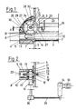
- Fig. 1 einen Schnitt durch eine Schneckenpresse im Aufriß und
- Fig. 2 einen Schnitt durch das Gehäuse des Abstreifrades in Draufsicht nach Schnitt A-B und die Antriebsanordnung schematisch.
- Von der Schneckenpresse ist nur der verdichtungsseitige Teil dargestellt. Dabei ist eine einseitig gelagerte (nicht dargestellt) Schnecke 1 mit ihrem zylindrischen Förderteil 2 in einem oben offenen Schneckentrog 3 angeordnet, an den ein konisches Mundstück 4 angesetzt ist, das in einem Gehäuse 5 angeordnet ist, das seinerseits am Maschinenrahmen 6 befestigt ist.
- In dem konischen Mundstück 4 ist ein konischer Schneckenteil 7 angeordnet, der den konischen Misch-und Verdichtungsteil der Schnecke 1 bildet.
- In den konischen Schneckenteil 7 greift von oben durch einen Längsspalt 8 des konischen Mundstückes 4 ein Abstreifrad 9 mit seiner - angedeuteten - Verzahnung zwischen die - angedeuteten - Schneckengänge,dessen Welle 10 eine Achse 11 senkrecht zur Längsachse 12 der Schnecke 1 aufweist.
- Das Abstreifrad 9 weist einen etwa fünffach größeren Durchmesser auf als der Kern 13 der Schnecke 1 an der Eingriffstelle 14 des Abstreifrades 9, sodaß die Umdrehungszahl entsprechend niedrig gehalten werden kann.
- Das Abstreifrad 9 ist mit der Welle 10 in beidseitigen Lagern 15,15′ im Gehäuse 5 gelagert,dessen Seitenwände 16, 16′ mit den beiden Stirnseiten 18,18′des Abstreifers 9 in Richtung auf eine Durchgangsöffnung 17 im Maschinenrahmen 6 zu jeweils einen sich erweiternden Spalt 19,19′ bilden,durch den der Raum 20 im Gehäuse 5 mit dem Raum 21 des offenen Schneckentroges 3 oberhalb der Schnecke 1 verbunden ist.
- Die beiden Stirnseiten 18,18′ des Abstreifrades 9 sind mit je vier Ausnehmungen 22 versehen, die regelmäßig verteilt angeordnet sind und radial von der Nabe 23 bis in den Bereich der Verzahnung 24 reichen.
- Oberhalb der Schnecke 1 ist im Raum 21 des offenen Schneckentroges 3 ein Zwischenförderer 25 für das zu pressende Gut angeordnet, dessen Drehachse 26 parallel zur Achse 12 der Schnecke 1 verläuft und dessen vorderes Ende 27 den Umfang des Abstreifrades 9 abstreift.
- Das Gehäuse 5 besitzt oberhalb des Abstreifrades 9 eine Öffnung 28, die mit einem Gehäusedeckel 29 verschließbar ist, der an seiner Innenseite mit einem Abstreifer 30 versehen ist, der das Abstreifrad 9 über einen Teil seines Umfanges umgibt und an seinen beiden Enden 31 und 32 das Abstreifrad 9 bei Vor- und bei Rücklauf abstreift.
- Der Antrieb des Abstreifrades 9 erfolgt synchron zum Antrieb der Schnecke 1 von einem Motor 33 des Hauptgetriebes 34 der Maschine aus über eine Zwischenwelle 35 und ein Zwischengetriebe 36, das zweckmäßig als Schneckengetriebe ausgebildet ist, auf die Welle 10.
- Beim Pressenlauf streift das Abstreifrad 9 den größten Teil des Preßgutes ab. Ein kleiner Teil wird durch den Längsspalt 8 in den Raum 20 des Gehäuses 5 mitgenommen und vom unteren Ende 31 des Abstreifers 30 am Umfang abgestreift. An den Stirnseiten 18,18′ des Abstreifrades 9 wirken die Wandungen des Längsspaltes 8 des konischen Mundstückes 4 als Abstreifer. Die Ausnehmungen 22 verringern dabei die auftretenden Reibungskräfte und wirken im Raum 20 des Gehäuses 5 als Förderhilfsmittel zur Beförderung des ausgetretenen Preßgutes durch die beiden sich erweiternden Spalte 19,19′ und die Durchgangsöffnung 17 in den Raum 21 des offenen Schneckentroges 3 oberhalb des Förderteiles 2 der Schnecke 1. Beim Rücklauf wird der Umfang des Abstreifrades 9 vom oberen Ende 32 des Abstreifers 30, sowie von den Wandungen des Längsspaltes 8 abgestreift und so der Rückfluss des ausgetretenen Preßgutes in den Misch-und Verdichtungsteil verhindert.
- Der synchrone Antrieb des Abstreifrades 9 sichert die Stellung von dessen Verzahnung zu dem Schneckengang.
-
- 1 Schnecke
- 2 Förderteil der Schnecke 1
- 3 Schneckentrog
- 4 konisches Mundstück
- 5 Gehäuse
- 6 Maschinenrahmen
- 7 konischer Schneckenteil
- 8 Längsspalt des konischen Mundstückes 4
- 9 Abstreifrad
- 10 Welle des Abstreifrades 9
- 11 Achse der Welle 10
- 12 Achse der Schnecke 1
- 13 Kern des konischen Schneckenteiles 7 an der Eingriffstelle 14
- 14 Eingriffstelle des Abstreifrades 9
- 15,15′ Lager der Welle 10
- 16,16′ Seitenwand des Gehäuses 5
- 17 Durchgangsöffnung im Maschinenrahmen 6
- 18,18′ Stirnseiten des Abstreifrades 9
- 19,19′ Spalt zwischen Seitenwand 16,16′ und Stirnseite 18,18′ des Abstreifrades 9
- 20 Raum des Gehäuses 5
- 21 Raum im offenen Schneckentrog 3 oberhalb der Schnecke 1
- 22 Ausnehmung an der Stirnseite 18,18′
- 23 Nabe des Abstreifrades 9
- 24 Verzahnung des Abstreifrades 9
- 25 Zwischenförderer
- 26 Drehachse des Zwischenförderers 25
- 27 vorderes Ende des Zwischenförderers 25
- 28 Öffnung des Gehäuses 5
- 29 Gehäusedeckel
- 30 Abstreifer des Gehäusedeckels 29
- 31 unteres Ende des Abstreifers 30
- 32 oberes Ende des Abstreifers 30
- 33 Motor
- 34 Hauptgetriebe
- 35 Zwischenwelle
- 36 Zwischengetriebe
Claims (8)
Priority Applications (1)
| Application Number | Priority Date | Filing Date | Title |
|---|---|---|---|
| AT88120509T ATE87541T1 (de) | 1987-12-21 | 1988-12-08 | Schneckenpresse. |
Applications Claiming Priority (2)
| Application Number | Priority Date | Filing Date | Title |
|---|---|---|---|
| DE19873743350 DE3743350A1 (de) | 1987-12-21 | 1987-12-21 | Schneckenpresse |
| DE3743350 | 1987-12-21 |
Publications (3)
| Publication Number | Publication Date |
|---|---|
| EP0326684A2 true EP0326684A2 (de) | 1989-08-09 |
| EP0326684A3 EP0326684A3 (en) | 1990-08-16 |
| EP0326684B1 EP0326684B1 (de) | 1993-03-31 |
Family
ID=6343154
Family Applications (1)
| Application Number | Title | Priority Date | Filing Date |
|---|---|---|---|
| EP88120509A Expired - Lifetime EP0326684B1 (de) | 1987-12-21 | 1988-12-08 | Schneckenpresse |
Country Status (3)
| Country | Link |
|---|---|
| EP (1) | EP0326684B1 (de) |
| AT (1) | ATE87541T1 (de) |
| DE (2) | DE3743350A1 (de) |
Cited By (2)
| Publication number | Priority date | Publication date | Assignee | Title |
|---|---|---|---|---|
| EP0451348A1 (de) * | 1990-04-06 | 1991-10-16 | Alois Pöttinger Maschinenfabrik GmbH | Schneckenpresse |
| CN105107425A (zh) * | 2015-08-31 | 2015-12-02 | 重庆达沃斯食品有限公司 | 螺旋藻造粒成型机 |
Family Cites Families (3)
| Publication number | Priority date | Publication date | Assignee | Title |
|---|---|---|---|---|
| GB191109826A (en) * | 1911-04-22 | 1912-04-22 | Jean Paul Bonnicart | Improvements in Machines for Compressing and Agglomerating Plastic or Powdered Materials. |
| GB171088A (en) * | 1920-11-03 | 1923-02-26 | Ladislas Penkala | Endless screw press |
| DE814098C (de) * | 1948-10-02 | 1951-09-20 | Wilhelm Neuscheler | Schneckenpresse |
-
1987
- 1987-12-21 DE DE19873743350 patent/DE3743350A1/de not_active Withdrawn
-
1988
- 1988-12-08 AT AT88120509T patent/ATE87541T1/de not_active IP Right Cessation
- 1988-12-08 DE DE8888120509T patent/DE3879925D1/de not_active Expired - Fee Related
- 1988-12-08 EP EP88120509A patent/EP0326684B1/de not_active Expired - Lifetime
Cited By (2)
| Publication number | Priority date | Publication date | Assignee | Title |
|---|---|---|---|---|
| EP0451348A1 (de) * | 1990-04-06 | 1991-10-16 | Alois Pöttinger Maschinenfabrik GmbH | Schneckenpresse |
| CN105107425A (zh) * | 2015-08-31 | 2015-12-02 | 重庆达沃斯食品有限公司 | 螺旋藻造粒成型机 |
Also Published As
| Publication number | Publication date |
|---|---|
| ATE87541T1 (de) | 1993-04-15 |
| DE3879925D1 (de) | 1993-05-06 |
| DE3743350A1 (de) | 1989-06-29 |
| EP0326684A3 (en) | 1990-08-16 |
| EP0326684B1 (de) | 1993-03-31 |
Similar Documents
| Publication | Publication Date | Title |
|---|---|---|
| DE3586241T2 (de) | Schneckenfoerderer. | |
| DE3224204A1 (de) | Zentrifuge | |
| EP0632961A1 (de) | Conche | |
| DE3888533T2 (de) | Entwässerungsschneckenpresse mit zwei oder mehr schraubenförmigen Elementen mit ineinandergreifenden Profilen. | |
| DE3517128A1 (de) | Einrichtung zum kneten von teigen fuer die brot- und backwarenherstellung und zum temperaturniedrigen ausfschliessen und homogenisieren von nahrungs- und futtermittelbestandteilen | |
| DE2830491A1 (de) | Volumetrische foerdervorrichtung fuer trockene materialien | |
| DE68920606T2 (de) | Vorrichtung zum Sieben von Papierstoffbrei und Flügel für die Siebvorrichtung. | |
| EP0326684B1 (de) | Schneckenpresse | |
| DE69308370T2 (de) | Schraubenpumpe | |
| DE1264398B (de) | Verfahren und Vorrichtung zum Auslaugen von zerkleinertem Material | |
| DE2513577B2 (de) | Kontinuierlich arbeitender Mischer für plastische Massen | |
| DE1757368C3 (de) | Vollmantel-Schneckenzentrifuge | |
| DE3226918C1 (de) | Schneckenextruder | |
| DE3140042A1 (de) | Schneckenpumpe | |
| DE3121583A1 (de) | Abbeermaschine | |
| DE69107118T2 (de) | Vorrichtung zur Abgabe von Teig. | |
| DE1165396B (de) | Kegelstoffmuehle zur Aufbereitung von Faserstoffen fuer die Papierherstellung | |
| DD227648B1 (de) | Vorrichtung zur beschickung von extrusionsmaschinen mit voluminoesen, schlecht rieselfaehigen verarbeitungsguetern, insbesondere thermoplastabfaellen | |
| DE257135C (de) | ||
| DE4414869C1 (de) | Maschine zur Herstellung von Brucheis | |
| DE2641597A1 (de) | Spindelschneckenpresse | |
| DE154146C (de) | ||
| DE3130269A1 (de) | "foerderschnecke, insbesondere fuer pastoese materialien" | |
| DE10034998C2 (de) | Zahnradextruder | |
| DE316290C (de) |
Legal Events
| Date | Code | Title | Description |
|---|---|---|---|
| PUAI | Public reference made under article 153(3) epc to a published international application that has entered the european phase |
Free format text: ORIGINAL CODE: 0009012 |
|
| AK | Designated contracting states |
Kind code of ref document: A2 Designated state(s): AT CH DE FR GB IT LI NL SE |
|
| PUAL | Search report despatched |
Free format text: ORIGINAL CODE: 0009013 |
|
| AK | Designated contracting states |
Kind code of ref document: A3 Designated state(s): AT CH DE FR GB IT LI NL SE |
|
| 17P | Request for examination filed |
Effective date: 19901212 |
|
| 17Q | First examination report despatched |
Effective date: 19920604 |
|
| GRAA | (expected) grant |
Free format text: ORIGINAL CODE: 0009210 |
|
| AK | Designated contracting states |
Kind code of ref document: B1 Designated state(s): AT CH DE FR GB IT LI NL SE |
|
| PG25 | Lapsed in a contracting state [announced via postgrant information from national office to epo] |
Ref country code: IT Free format text: LAPSE BECAUSE OF FAILURE TO SUBMIT A TRANSLATION OF THE DESCRIPTION OR TO PAY THE FEE WITHIN THE PRESCRIBED TIME-LIMIT;WARNING: LAPSES OF ITALIAN PATENTS WITH EFFECTIVE DATE BEFORE 2007 MAY HAVE OCCURRED AT ANY TIME BEFORE 2007. THE CORRECT EFFECTIVE DATE MAY BE DIFFERENT FROM THE ONE RECORDED. Effective date: 19930331 Ref country code: GB Effective date: 19930331 Ref country code: FR Effective date: 19930331 Ref country code: SE Effective date: 19930331 Ref country code: NL Effective date: 19930331 |
|
| REF | Corresponds to: |
Ref document number: 87541 Country of ref document: AT Date of ref document: 19930415 Kind code of ref document: T |
|
| REF | Corresponds to: |
Ref document number: 3879925 Country of ref document: DE Date of ref document: 19930506 |
|
| EN | Fr: translation not filed | ||
| NLV1 | Nl: lapsed or annulled due to failure to fulfill the requirements of art. 29p and 29m of the patents act | ||
| GBV | Gb: ep patent (uk) treated as always having been void in accordance with gb section 77(7)/1977 [no translation filed] |
Effective date: 19930331 |
|
| PGFP | Annual fee paid to national office [announced via postgrant information from national office to epo] |
Ref country code: DE Payment date: 19931115 Year of fee payment: 6 |
|
| PGFP | Annual fee paid to national office [announced via postgrant information from national office to epo] |
Ref country code: AT Payment date: 19931119 Year of fee payment: 6 |
|
| PG25 | Lapsed in a contracting state [announced via postgrant information from national office to epo] |
Ref country code: LI Effective date: 19931231 Ref country code: CH Effective date: 19931231 |
|
| PLBE | No opposition filed within time limit |
Free format text: ORIGINAL CODE: 0009261 |
|
| STAA | Information on the status of an ep patent application or granted ep patent |
Free format text: STATUS: NO OPPOSITION FILED WITHIN TIME LIMIT |
|
| 26N | No opposition filed | ||
| REG | Reference to a national code |
Ref country code: CH Ref legal event code: PL |
|
| PG25 | Lapsed in a contracting state [announced via postgrant information from national office to epo] |
Ref country code: AT Effective date: 19941208 |
|
| PG25 | Lapsed in a contracting state [announced via postgrant information from national office to epo] |
Ref country code: DE Effective date: 19950901 |