EP0325706B1 - Mehrwalzen-Beschichtungs- und Kaschierkalander zum Herstellen einer Verbundbahn aus Kunststoff- oder Kautschukfolien und textilen Verstärkungsbahnen - Google Patents
Mehrwalzen-Beschichtungs- und Kaschierkalander zum Herstellen einer Verbundbahn aus Kunststoff- oder Kautschukfolien und textilen Verstärkungsbahnen Download PDFInfo
- Publication number
- EP0325706B1 EP0325706B1 EP88118218A EP88118218A EP0325706B1 EP 0325706 B1 EP0325706 B1 EP 0325706B1 EP 88118218 A EP88118218 A EP 88118218A EP 88118218 A EP88118218 A EP 88118218A EP 0325706 B1 EP0325706 B1 EP 0325706B1
- Authority
- EP
- European Patent Office
- Prior art keywords
- roll
- calender
- laminating
- rolls
- roller
- Prior art date
- Legal status (The legal status is an assumption and is not a legal conclusion. Google has not performed a legal analysis and makes no representation as to the accuracy of the status listed.)
- Expired - Lifetime
Links
Images

Classifications
-
- B—PERFORMING OPERATIONS; TRANSPORTING
- B29—WORKING OF PLASTICS; WORKING OF SUBSTANCES IN A PLASTIC STATE IN GENERAL
- B29C—SHAPING OR JOINING OF PLASTICS; SHAPING OF MATERIAL IN A PLASTIC STATE, NOT OTHERWISE PROVIDED FOR; AFTER-TREATMENT OF THE SHAPED PRODUCTS, e.g. REPAIRING
- B29C43/00—Compression moulding, i.e. applying external pressure to flow the moulding material; Apparatus therefor
- B29C43/22—Compression moulding, i.e. applying external pressure to flow the moulding material; Apparatus therefor of articles of indefinite length
- B29C43/24—Calendering
-
- B—PERFORMING OPERATIONS; TRANSPORTING
- B29—WORKING OF PLASTICS; WORKING OF SUBSTANCES IN A PLASTIC STATE IN GENERAL
- B29C—SHAPING OR JOINING OF PLASTICS; SHAPING OF MATERIAL IN A PLASTIC STATE, NOT OTHERWISE PROVIDED FOR; AFTER-TREATMENT OF THE SHAPED PRODUCTS, e.g. REPAIRING
- B29C43/00—Compression moulding, i.e. applying external pressure to flow the moulding material; Apparatus therefor
- B29C43/22—Compression moulding, i.e. applying external pressure to flow the moulding material; Apparatus therefor of articles of indefinite length
- B29C43/28—Compression moulding, i.e. applying external pressure to flow the moulding material; Apparatus therefor of articles of indefinite length incorporating preformed parts or layers, e.g. compression moulding around inserts or for coating articles
Definitions
- the invention relates to a multi-roll calender of the type as described in the preamble of claim 1.
- a calender is known from US Pat. No. 3,455,756, on which a plastic film is produced and then laminated with a further web on a separate device.
- the calender is followed by a laminating device consisting of two rollers, on which the film produced on the calender is laminated together with a reinforcing web or the like.
- the calender should be used both as a coating calender for fabric webs or the like and alternatively as a pure lamination calender. Furthermore, the coating and laminating calender is intended to provide an optimal, high-quality coating process for a fabric web with a plastic film produced on the calender itself, as well as an excellent laminating process, starting from an already finished one to be laminated onto a fabric Be plastic film feasible.
- the follow-up devices such as the laminating calender, were spatially separated from the film production calender, whereby the space requirement of the system increases considerably and the price of the overall system is at least a third higher.
- the further feature namely the arrangement of the preheating roller and the laminating roller together with the fixed roller approximately on a plane drawn through the longitudinal central axis of all three rollers, ensures that the deflection of the last roller, caused by the calendering work generated in the last calender nip, by means of a counter-bending device , which is articulated to additional bearings arranged on the outside of both roller journals, can be effectively lifted without the Parallelism of the rollers is lost.
- the arrangement of the preheating roller and laminating roller with the fixed roller of the calender at about a common level has the decisive advantage that automatic control of the film produced on the calender and laminated together with a fabric web can be carried out with regard to its thickness uniformity, because for influencing the Film thickness in the last calender nip the penultimate roller can be adjusted using the backdrop. Even in such a case, the last roller is not adjusted and the parallel gaps between this roller and the preheating roller and the laminating roller are retained without the spatial separation of the film manufacturing calender from the laminating calender having to be carried out.
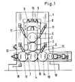
- the calender system shown in Fig. 1 is composed of the calender for the production of the plastic film, e.g. a PVC film and the part of the system that is used for coating and laminating.
- the calender rolls 2 and 3 with their bearing bodies 5 and 6 are arranged in a backdrop 8 which can be moved in the direction of the arrow.
- the setting 8 is raised and lowered together with the rollers by means of the indicated adjusting gear 9 in order to be able to set the gap or the working thickness between the rollers 3 and 4.
- the roller 4 is arranged on its bearing bodies 7 as a fixed roller in the stands 1, i.e. that this roller has no vertical adjustment, such as rollers 2 and 3, and also no inclination adjustment device to compensate for the roller deflection, caused by the splitting forces when calendering films.
- counter-bending devices 11 and 12 are indicated in FIG. 1, which are actuated by means of hydraulic cylinders which are supported on the calender stands, and as a result of which the calender rollers are counter-bent, ie can be held in their position.
- the calendering work in the roll nips causes the rolls to bend outwards.
- the rollers are bent back by the counter-bending devices, ie are held approximately in their position.
- the preheating roller 13 is upstream of the roller 4 and the laminating roller 14 is arranged downstream.
- the composite web can then, depending on requirements, be embossed in the gap 19.
- FIG. 2 shows the calender system, in the form of a pure laminating calender.
- the two rollers 2 and 3 mounted in the link 8 were raised by the roller 4 by means of the indicated adjusting gear 9 and the drives of the rollers 2 and 3 were switched off.
- a further film or a prefabricated composite web 17 is fed to the preheating roller 13 via a deflection roller and stitched together in the gap between the fixed roller 4 and the preheating roller 13 with a textile reinforcement web 18 or also with another foil or with a foil composite.
- the system shown in Fig. 2 can thus also be used as a lamination calender.
Landscapes
- Engineering & Computer Science (AREA)
- Mechanical Engineering (AREA)
- Casting Or Compression Moulding Of Plastics Or The Like (AREA)
- Laminated Bodies (AREA)
- Moulding By Coating Moulds (AREA)
- Shaping Of Tube Ends By Bending Or Straightening (AREA)
Applications Claiming Priority (2)
| Application Number | Priority Date | Filing Date | Title |
|---|---|---|---|
| DE3801902A DE3801902C1 (enExample) | 1988-01-23 | 1988-01-23 | |
| DE3801902 | 1988-01-23 |
Publications (3)
| Publication Number | Publication Date |
|---|---|
| EP0325706A2 EP0325706A2 (de) | 1989-08-02 |
| EP0325706A3 EP0325706A3 (en) | 1990-08-01 |
| EP0325706B1 true EP0325706B1 (de) | 1993-09-08 |
Family
ID=6345833
Family Applications (1)
| Application Number | Title | Priority Date | Filing Date |
|---|---|---|---|
| EP88118218A Expired - Lifetime EP0325706B1 (de) | 1988-01-23 | 1988-11-02 | Mehrwalzen-Beschichtungs- und Kaschierkalander zum Herstellen einer Verbundbahn aus Kunststoff- oder Kautschukfolien und textilen Verstärkungsbahnen |
Country Status (4)
| Country | Link |
|---|---|
| EP (1) | EP0325706B1 (enExample) |
| JP (1) | JP2653385B2 (enExample) |
| CN (1) | CN1015159B (enExample) |
| DE (2) | DE3801902C1 (enExample) |
Families Citing this family (6)
| Publication number | Priority date | Publication date | Assignee | Title |
|---|---|---|---|---|
| JP2002018979A (ja) * | 2000-07-07 | 2002-01-22 | Bridgestone Corp | コーティングカレンダー、コーティングカレンダーユニット及びコーティング荷重の制御方法 |
| CN1302920C (zh) * | 2004-08-10 | 2007-03-07 | 富士普拉株式会社 | 层压机 |
| CN102069546A (zh) * | 2010-11-24 | 2011-05-25 | 上海泓阳机械有限公司 | 一种辊筒t型排列橡塑压延机及其操作方法 |
| CA3018516A1 (en) | 2017-09-26 | 2019-03-26 | Davis-Standard, Llc | Casting apparatus for manufacturing polymer film |
| CN116856137A (zh) * | 2023-09-04 | 2023-10-10 | 莱州联友金浩新型材料有限公司 | 一种多孔纤维膜材料的热轧光设备及热轧工艺 |
| CN119329023B (zh) * | 2024-12-20 | 2025-03-28 | 山东建通土工材料有限公司 | 一种平膜挤出成膜热风复合土工膜生产装置及工艺 |
Family Cites Families (5)
| Publication number | Priority date | Publication date | Assignee | Title |
|---|---|---|---|---|
| US1603813A (en) * | 1924-11-08 | 1926-10-19 | Stein Jacob | Apparatus for making striped rubber sheeting |
| DE893260C (de) * | 1951-07-01 | 1953-10-15 | Erich Devermann | Kalander oder Walzwerk, insbesondere Ziehkalander |
| DE894767C (de) * | 1952-03-04 | 1953-10-26 | Eck & Soehne Joseph | Kalander in Z-foermiger Walzenanordnung |
| DE1546543A1 (de) * | 1964-02-05 | 1970-10-08 | Gen Tire & Rubber Co | Verfahren zur Herstellung von durchbrochenen Mustern in Kunststoffbahnen |
| US3361609A (en) * | 1965-06-16 | 1968-01-02 | Com Tech Inc | Production process for embossable medium |
-
1988
- 1988-01-23 DE DE3801902A patent/DE3801902C1/de not_active Expired
- 1988-11-02 EP EP88118218A patent/EP0325706B1/de not_active Expired - Lifetime
- 1988-11-02 DE DE88118218T patent/DE3883962D1/de not_active Expired - Fee Related
- 1988-12-08 CN CN88108385A patent/CN1015159B/zh not_active Expired
-
1989
- 1989-01-23 JP JP1012049A patent/JP2653385B2/ja not_active Expired - Lifetime
Also Published As
| Publication number | Publication date |
|---|---|
| JPH01226315A (ja) | 1989-09-11 |
| EP0325706A2 (de) | 1989-08-02 |
| CN1034504A (zh) | 1989-08-09 |
| DE3801902C1 (enExample) | 1989-03-02 |
| CN1015159B (zh) | 1991-12-25 |
| EP0325706A3 (en) | 1990-08-01 |
| DE3883962D1 (de) | 1993-10-14 |
| JP2653385B2 (ja) | 1997-09-17 |
Similar Documents
| Publication | Publication Date | Title |
|---|---|---|
| DE69411971T3 (de) | Warmwalzwerk für Stahlblech und Walzverfahren | |
| DE2543738C3 (de) | Kalander für Folien aus thermoplastischem Kunststoff oder elastomerem Material | |
| DE69209043T2 (de) | Walzwerk, Walzverfahren und Walzwerksystem | |
| DE1527601A1 (de) | Walzwerk | |
| EP0735185A2 (de) | Kalander für die zweiseitige Papierbehandlung | |
| EP1365869B1 (de) | Walzgerüst zur herstellung planer walzbänder mit gewünschter bandprofilüberhöhung | |
| DE69407218T3 (de) | Verfahren zur Blechballigkeitsregelung und Anlage für endloses Walzen | |
| EP0325706B1 (de) | Mehrwalzen-Beschichtungs- und Kaschierkalander zum Herstellen einer Verbundbahn aus Kunststoff- oder Kautschukfolien und textilen Verstärkungsbahnen | |
| DE1452152B2 (de) | Walzwerk zur Herstellung von Flachprodukten, insbesondere von Blechen und Bändern | |
| DE2848295C2 (de) | Kalander zur Herstellung von thermoplastischer Folien | |
| DE1629809A1 (de) | Vorrichtung und Verfahren zur Herstellung einheitlich kalandrierten Materials | |
| DE3300251C2 (enExample) | ||
| DE60115440T2 (de) | Arbeitswalze zur herstellung von metallfolien | |
| DE19508349C2 (de) | Kalander für die Behandlung einer Papierbahn und Verfahren zu dessen Betrieb | |
| DE69612225T2 (de) | Verfahren und Vorrichtung zum Richten von flachen metallischen Produkten sowie Blechen, Metallbanden | |
| EP0181474B1 (de) | Sechs-Walzen-Walzwerk | |
| AT232840B (de) | Kalandriermaschine für Papier od. dgl. bahnenförmiges Material | |
| EP0907509B1 (de) | Kaschierwerk zur herstellung eines schichtverbundes | |
| DE2034490A1 (en) | Roller pivot bearing compensator - hydraulically operated | |
| DE2316981A1 (de) | Kalander fuer die verarbeitung von gummi und kunststoff | |
| DE102009048074A1 (de) | Reckwalze sowie zugehöriges Längsreckwerk oder -stufe | |
| DE3039186C2 (de) | Verfahren und Vorrichtung zum Herstellen einer beschichteten Gewebebahn | |
| DE3302333A1 (de) | Verfahren und vorrichtung zur einstellung der breite und dicke eines bandstahls | |
| DE1729821C3 (de) | Kalander zur Herstellung von It-Dichtungsplatten | |
| DE3229477A1 (de) | Kalander insbesondere zur herstellung von kunststoffolien |
Legal Events
| Date | Code | Title | Description |
|---|---|---|---|
| PUAI | Public reference made under article 153(3) epc to a published international application that has entered the european phase |
Free format text: ORIGINAL CODE: 0009012 |
|
| AK | Designated contracting states |
Kind code of ref document: A2 Designated state(s): DE FR GB IT |
|
| PUAL | Search report despatched |
Free format text: ORIGINAL CODE: 0009013 |
|
| AK | Designated contracting states |
Kind code of ref document: A3 Designated state(s): DE FR GB IT |
|
| 17P | Request for examination filed |
Effective date: 19900615 |
|
| 17Q | First examination report despatched |
Effective date: 19921009 |
|
| ITF | It: translation for a ep patent filed | ||
| GRAA | (expected) grant |
Free format text: ORIGINAL CODE: 0009210 |
|
| AK | Designated contracting states |
Kind code of ref document: B1 Designated state(s): DE FR GB IT |
|
| REF | Corresponds to: |
Ref document number: 3883962 Country of ref document: DE Date of ref document: 19931014 |
|
| ET | Fr: translation filed | ||
| GBT | Gb: translation of ep patent filed (gb section 77(6)(a)/1977) |
Effective date: 19931020 |
|
| PLBE | No opposition filed within time limit |
Free format text: ORIGINAL CODE: 0009261 |
|
| STAA | Information on the status of an ep patent application or granted ep patent |
Free format text: STATUS: NO OPPOSITION FILED WITHIN TIME LIMIT |
|
| 26N | No opposition filed | ||
| PGFP | Annual fee paid to national office [announced via postgrant information from national office to epo] |
Ref country code: DE Payment date: 19980918 Year of fee payment: 11 |
|
| PGFP | Annual fee paid to national office [announced via postgrant information from national office to epo] |
Ref country code: GB Payment date: 19981029 Year of fee payment: 11 |
|
| PGFP | Annual fee paid to national office [announced via postgrant information from national office to epo] |
Ref country code: FR Payment date: 19981118 Year of fee payment: 11 |
|
| PG25 | Lapsed in a contracting state [announced via postgrant information from national office to epo] |
Ref country code: GB Free format text: LAPSE BECAUSE OF NON-PAYMENT OF DUE FEES Effective date: 19991102 |
|
| GBPC | Gb: european patent ceased through non-payment of renewal fee |
Effective date: 19991102 |
|
| PG25 | Lapsed in a contracting state [announced via postgrant information from national office to epo] |
Ref country code: FR Free format text: LAPSE BECAUSE OF NON-PAYMENT OF DUE FEES Effective date: 20000731 |
|
| PG25 | Lapsed in a contracting state [announced via postgrant information from national office to epo] |
Ref country code: DE Free format text: LAPSE BECAUSE OF NON-PAYMENT OF DUE FEES Effective date: 20000901 |
|
| REG | Reference to a national code |
Ref country code: FR Ref legal event code: ST |
|
| PG25 | Lapsed in a contracting state [announced via postgrant information from national office to epo] |
Ref country code: IT Free format text: LAPSE BECAUSE OF NON-PAYMENT OF DUE FEES;WARNING: LAPSES OF ITALIAN PATENTS WITH EFFECTIVE DATE BEFORE 2007 MAY HAVE OCCURRED AT ANY TIME BEFORE 2007. THE CORRECT EFFECTIVE DATE MAY BE DIFFERENT FROM THE ONE RECORDED. Effective date: 20051102 |