EP0325706B1 - Multi-roll coating and laminating calender for the production of composite bands consisting of a plastic or rubber foil of a reinforcing textile band - Google Patents
Multi-roll coating and laminating calender for the production of composite bands consisting of a plastic or rubber foil of a reinforcing textile band Download PDFInfo
- Publication number
- EP0325706B1 EP0325706B1 EP88118218A EP88118218A EP0325706B1 EP 0325706 B1 EP0325706 B1 EP 0325706B1 EP 88118218 A EP88118218 A EP 88118218A EP 88118218 A EP88118218 A EP 88118218A EP 0325706 B1 EP0325706 B1 EP 0325706B1
- Authority
- EP
- European Patent Office
- Prior art keywords
- roll
- calender
- laminating
- rolls
- roller
- Prior art date
- Legal status (The legal status is an assumption and is not a legal conclusion. Google has not performed a legal analysis and makes no representation as to the accuracy of the status listed.)
- Expired - Lifetime
Links
- 238000010030 laminating Methods 0.000 title claims description 29
- 238000000576 coating method Methods 0.000 title claims description 12
- 239000011248 coating agent Substances 0.000 title claims description 9
- 239000002131 composite material Substances 0.000 title claims description 8
- 238000004519 manufacturing process Methods 0.000 title claims description 6
- 230000003014 reinforcing effect Effects 0.000 title claims description 3
- 239000011888 foil Substances 0.000 title description 3
- 239000004753 textile Substances 0.000 title description 2
- 238000003490 calendering Methods 0.000 claims description 5
- 239000004744 fabric Substances 0.000 claims description 5
- 239000002985 plastic film Substances 0.000 claims description 5
- 229920006255 plastic film Polymers 0.000 claims description 5
- 238000011144 upstream manufacturing Methods 0.000 claims description 2
- 238000013000 roll bending Methods 0.000 claims 1
- 238000000034 method Methods 0.000 description 5
- 238000010438 heat treatment Methods 0.000 description 4
- 238000003475 lamination Methods 0.000 description 4
- 238000005452 bending Methods 0.000 description 3
- 238000010276 construction Methods 0.000 description 2
- 238000004049 embossing Methods 0.000 description 1
- 230000002787 reinforcement Effects 0.000 description 1
- 230000000717 retained effect Effects 0.000 description 1
- 238000000926 separation method Methods 0.000 description 1
Images

Classifications
-
- B—PERFORMING OPERATIONS; TRANSPORTING
- B29—WORKING OF PLASTICS; WORKING OF SUBSTANCES IN A PLASTIC STATE IN GENERAL
- B29C—SHAPING OR JOINING OF PLASTICS; SHAPING OF MATERIAL IN A PLASTIC STATE, NOT OTHERWISE PROVIDED FOR; AFTER-TREATMENT OF THE SHAPED PRODUCTS, e.g. REPAIRING
- B29C43/00—Compression moulding, i.e. applying external pressure to flow the moulding material; Apparatus therefor
- B29C43/22—Compression moulding, i.e. applying external pressure to flow the moulding material; Apparatus therefor of articles of indefinite length
- B29C43/24—Calendering
-
- B—PERFORMING OPERATIONS; TRANSPORTING
- B29—WORKING OF PLASTICS; WORKING OF SUBSTANCES IN A PLASTIC STATE IN GENERAL
- B29C—SHAPING OR JOINING OF PLASTICS; SHAPING OF MATERIAL IN A PLASTIC STATE, NOT OTHERWISE PROVIDED FOR; AFTER-TREATMENT OF THE SHAPED PRODUCTS, e.g. REPAIRING
- B29C43/00—Compression moulding, i.e. applying external pressure to flow the moulding material; Apparatus therefor
- B29C43/22—Compression moulding, i.e. applying external pressure to flow the moulding material; Apparatus therefor of articles of indefinite length
- B29C43/28—Compression moulding, i.e. applying external pressure to flow the moulding material; Apparatus therefor of articles of indefinite length incorporating preformed parts or layers, e.g. compression moulding around inserts or for coating articles
Definitions
- the invention relates to a multi-roll calender of the type as described in the preamble of claim 1.
- a calender is known from US Pat. No. 3,455,756, on which a plastic film is produced and then laminated with a further web on a separate device.
- the calender is followed by a laminating device consisting of two rollers, on which the film produced on the calender is laminated together with a reinforcing web or the like.
- the calender should be used both as a coating calender for fabric webs or the like and alternatively as a pure lamination calender. Furthermore, the coating and laminating calender is intended to provide an optimal, high-quality coating process for a fabric web with a plastic film produced on the calender itself, as well as an excellent laminating process, starting from an already finished one to be laminated onto a fabric Be plastic film feasible.
- the follow-up devices such as the laminating calender, were spatially separated from the film production calender, whereby the space requirement of the system increases considerably and the price of the overall system is at least a third higher.
- the further feature namely the arrangement of the preheating roller and the laminating roller together with the fixed roller approximately on a plane drawn through the longitudinal central axis of all three rollers, ensures that the deflection of the last roller, caused by the calendering work generated in the last calender nip, by means of a counter-bending device , which is articulated to additional bearings arranged on the outside of both roller journals, can be effectively lifted without the Parallelism of the rollers is lost.
- the arrangement of the preheating roller and laminating roller with the fixed roller of the calender at about a common level has the decisive advantage that automatic control of the film produced on the calender and laminated together with a fabric web can be carried out with regard to its thickness uniformity, because for influencing the Film thickness in the last calender nip the penultimate roller can be adjusted using the backdrop. Even in such a case, the last roller is not adjusted and the parallel gaps between this roller and the preheating roller and the laminating roller are retained without the spatial separation of the film manufacturing calender from the laminating calender having to be carried out.
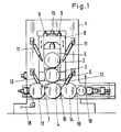
- the calender system shown in Fig. 1 is composed of the calender for the production of the plastic film, e.g. a PVC film and the part of the system that is used for coating and laminating.
- the calender rolls 2 and 3 with their bearing bodies 5 and 6 are arranged in a backdrop 8 which can be moved in the direction of the arrow.
- the setting 8 is raised and lowered together with the rollers by means of the indicated adjusting gear 9 in order to be able to set the gap or the working thickness between the rollers 3 and 4.
- the roller 4 is arranged on its bearing bodies 7 as a fixed roller in the stands 1, i.e. that this roller has no vertical adjustment, such as rollers 2 and 3, and also no inclination adjustment device to compensate for the roller deflection, caused by the splitting forces when calendering films.
- counter-bending devices 11 and 12 are indicated in FIG. 1, which are actuated by means of hydraulic cylinders which are supported on the calender stands, and as a result of which the calender rollers are counter-bent, ie can be held in their position.
- the calendering work in the roll nips causes the rolls to bend outwards.
- the rollers are bent back by the counter-bending devices, ie are held approximately in their position.
- the preheating roller 13 is upstream of the roller 4 and the laminating roller 14 is arranged downstream.
- the composite web can then, depending on requirements, be embossed in the gap 19.
- FIG. 2 shows the calender system, in the form of a pure laminating calender.
- the two rollers 2 and 3 mounted in the link 8 were raised by the roller 4 by means of the indicated adjusting gear 9 and the drives of the rollers 2 and 3 were switched off.
- a further film or a prefabricated composite web 17 is fed to the preheating roller 13 via a deflection roller and stitched together in the gap between the fixed roller 4 and the preheating roller 13 with a textile reinforcement web 18 or also with another foil or with a foil composite.
- the system shown in Fig. 2 can thus also be used as a lamination calender.
Landscapes
- Engineering & Computer Science (AREA)
- Mechanical Engineering (AREA)
- Casting Or Compression Moulding Of Plastics Or The Like (AREA)
- Laminated Bodies (AREA)
- Moulding By Coating Moulds (AREA)
- Shaping Of Tube Ends By Bending Or Straightening (AREA)
Description
Die Erfindung betrifft einen Mehrwalzen-Kalander der Gattung, wie beschrieben im Oberbegriff von Patentanspruch 1.The invention relates to a multi-roll calender of the type as described in the preamble of claim 1.
Aus der US-PS 3,455,756 ist ein Kalander bekannt, auf dem eine Kunststoffolie hergestellt und danach auf einer separaten Einrichtung mit einer weiteren Bahn kaschiert wird. Zu diesem Zweck ist dem Kalander eine aus zwei Walzen bestehende Kaschiereinrichtung nachgeordnet, auf der die auf dem Kalander hergestellte Folie mit einer Verstärkungsbahn oder dergl. zusammenkaschiert wird.A calender is known from US Pat. No. 3,455,756, on which a plastic film is produced and then laminated with a further web on a separate device. For this purpose, the calender is followed by a laminating device consisting of two rollers, on which the film produced on the calender is laminated together with a reinforcing web or the like.
Es ist die Aufgabe der vorliegenden Erfindung, eine Kaschiereinrichtung, wie gezeigt in der US-PS 3,455,756, konstruktiv stark zu vereinfachen. Der Kalander soll sowohl als Beschichtungskalander für Gewebebahnen oder dergleichen als auch alternativ als reiner Kaschierkalander einsetzbar sein. Weiterhin soll mit dem Beschichtungs- und Kaschierkalander ein optimaler hochqualitativer Beschichtungsvorgang einer Gewebebahn mit einer auf dem Kalander selbst herstellten Kunststoffolie als auch ein ausgezeichneter Kaschiervorgang, ausgehend von einer bereits fertigen, auf ein Gewebe zu kaschierenden Kunststoffolie durchführbar sein.It is the object of the present invention to greatly simplify the construction of a laminating device, as shown in US Pat. No. 3,455,756. The calender should be used both as a coating calender for fabric webs or the like and alternatively as a pure lamination calender. Furthermore, the coating and laminating calender is intended to provide an optimal, high-quality coating process for a fabric web with a plastic film produced on the calender itself, as well as an excellent laminating process, starting from an already finished one to be laminated onto a fabric Be plastic film feasible.
Die Aufgabe wird durch die im kennzeichnenden Teil des Patentanspruchs genannten Merkmale gelöst.The object is achieved by the features mentioned in the characterizing part of the patent claim.
Durch die Anordnung der in Arbeitsrichtung letzten Walze des Folienherstellkalanders in den Kalanderständern als Festwalze wird erreicht, daß diese Walze gleichzeitig sowohl
- Kalandrierarbeit leistet im Spalt zwischen der vorletzen und letzten Walze, als insbesondere auch
- einen Beschichtungsvorgang im Spalt zwischen einer Aufheizwalze und der letzten Walze durchführt und
- einen weiteren Kaschiervorgang im Spalt zwischen der letzten Kalanderwalze und einer Kaschierwalze durchgeführt.
- Calendering works in the gap between the penultimate and last roll, as well as in particular
- performs a coating process in the nip between a heating roller and the last roller and
- another laminating process in the gap between the last calender roll and a laminating roll.
Es wird in erster Linie jedoch eine erhebliche Vereinfachung der Gesamtkonstruktion und die Einsparung einer Kaschierwalze erreicht.In the first place, however, a considerable simplification of the overall construction and the saving of a laminating roller are achieved.
Diese Vorteile sind durch die Anordnung der in Arbeitsrichtung letzten Kalanderwalze als Festwalze realisierbar, weil einer, nicht zur Kalanderspaltverstellung herangezogenen Walze weitere Walzen, wie die Aufheizwalze und die Kaschierwalze zugeordnet werden können, was jedoch nur möglich ist, wenn diese Walze nicht verstellt, d.h. aus der Ebene der Walzen herausgefahren werden muß.These advantages can be realized by arranging the last calender roll in the working direction as a fixed roll, because a roll that is not used for calender gap adjustment can be assigned further rolls, such as the heating roll and the laminating roll, which is only possible if this roll is not adjusted, i.e. must be moved out of the plane of the rollers.
Wenn die letzte Walze eines Beschichtungs- und Kaschierkalanders beweglich gestaltet wird, was in der Vergangenheit der Fall war, müssen
- die Nachfolgeeinrichtungen, wie die den Beschichtungsvorgang durchführende Einrichtung oder die den Kaschiervorgang durchführende Einrichtung räumlich vom Kalander getrennt angeordnet werden, oder
- die Nachfolgeeinrichtungen müssen zwingend zusammen mit der letzten Walze (wenn diese verstellbar ausgebildet ist) mitverstellt werden, was einen erheblichen maschinellen Aufwand erfordert.
- the successor devices, such as the device carrying out the coating process or the device carrying out the laminating process, are arranged spatially separate from the calender, or
- the follow-up devices must be moved along with the last roller (if this is adjustable), which requires considerable mechanical effort.
Die Mitverstellung der Nachfolgeeinrichtungen mit der Verstellung der letzten Walze wäre deshalb nötig, weil sonst der unabdingbar für eine gleichbleibende Beschichtungsdicke erforderliche parallele Walzenspalt zwischen der letzten Kalanderwalze und der Aufheizwalze bzw. der Kaschierwalze verloren geht.The adjustment of the successor devices with the adjustment of the last roller would be necessary because otherwise the parallel nip required for a constant coating thickness between the last calender roller and the heating roller or the laminating roller would be lost.
Da die Mitverstellung der Nachfolgeeinrichtungen sehr unwirtschaftlich ist, wurden die Nachfolgeeinrichtungen, wie der Kaschierkalander, räumlich vom Folienherstellungskalander getrennt, wodurch der Platzbedarf der Anlage beträchtlich steigt und die Gesamtanlage im Preis um mindestens ein Drittel teurer wird.Since the co-adjustment of the follow-up devices is very uneconomical, the follow-up devices, such as the laminating calender, were spatially separated from the film production calender, whereby the space requirement of the system increases considerably and the price of the overall system is at least a third higher.
Durch das weitere Merkmal, nämlich die Anordnung der Vorwärmwalze und der Kaschierwalze zusammen mit der Festwalze etwa auf einer durch die Längsmittelachse aller drei Walzen gezogenen Ebene, wird erreicht, daß die Durchbiegung der letzten Walze, verursacht durch die im letzten Kalanderspalt erzeugte Kalandrierarbeit mittels einer Gegenbiegeeinrichtung, die an auf beiden Walzenzapfen außen angeordneten Zusatzlagern angelenkt ist, wirkungsvoll aufgehoben werden kann, ohne daß die Parallelität der Walzen verloren geht.The further feature, namely the arrangement of the preheating roller and the laminating roller together with the fixed roller approximately on a plane drawn through the longitudinal central axis of all three rollers, ensures that the deflection of the last roller, caused by the calendering work generated in the last calender nip, by means of a counter-bending device , which is articulated to additional bearings arranged on the outside of both roller journals, can be effectively lifted without the Parallelism of the rollers is lost.
Insbesondere hat jedoch die Anordnung der Vorwärmwalze und Kaschierwalze mit der Festwalze des Kalanders etwa auf einer gemeinsamen Ebene den entscheidenden Vorteil, daß eine automatische Regelung der auf dem Kalander hergestellten und mit einer Gewebebahn zusammenkaschierten Folie hinsichtlich ihrer Dickengleichmäßigkeit durchgeführt werden kann, weil für die Beeinflussung der Foliendicke im letzten Kalanderspalt die vorletzte Walze mittels der Kulisse verstellt werden kann. Auch in einem solchen Fall wird die letzte Walze nicht verstellt und die parallelen Spalte zwischen dieser Walze und der Vorwärmwalze und der Kaschierwalze bleiben erhalten, ohne daß eine räumliche Trennung des Folienherstellkalanders von dem Kaschierkalander vorgenommen werden muß.In particular, however, the arrangement of the preheating roller and laminating roller with the fixed roller of the calender at about a common level has the decisive advantage that automatic control of the film produced on the calender and laminated together with a fabric web can be carried out with regard to its thickness uniformity, because for influencing the Film thickness in the last calender nip the penultimate roller can be adjusted using the backdrop. Even in such a case, the last roller is not adjusted and the parallel gaps between this roller and the preheating roller and the laminating roller are retained without the spatial separation of the film manufacturing calender from the laminating calender having to be carried out.
Der größte Vorteil der Anordnung der Walzen in der Reihenfolge
- Vorheizwalze,
- letzte Kalanderwalze als Festwalze,
- Kaschierwalze
- Preheating roller,
- last calender roll as fixed roll,
- Laminating roller
Ausführungsbeispiele von als Beschichtungs- oder Kaschierkalander einzusetzende Kalanderanlagen werden in den Zeichnungen gezeigt und nachfolgend erläutert.Exemplary embodiments of calender systems to be used as coating or laminating calenders are shown in the drawings and explained below.
Es zeigen:
- Fig. 1
- einen schematisierten Querschnitt durch eine Kalanderanlage.
- Fig. 2
- einen schematisierten Querschnitt durch eine Anlage ähnlich der Anlage in Fig. 1, jedoch als Kaschierkalander umgestellt.
- Fig. 1
- a schematic cross section a calender system.
- Fig. 2
- a schematic cross section through a system similar to the system in Fig. 1, but converted as a laminating calender.
Die in Fig. 1 gezeigte Kalanderanlage setzt sich zusammen aus dem Kalander für die Herstellung der Kunststoffolie, z.B. einer PVC-Folie und dem Teil der Anlage, der zum Beschichten und Kaschieren eingesetzt wird.The calender system shown in Fig. 1 is composed of the calender for the production of the plastic film, e.g. a PVC film and the part of the system that is used for coating and laminating.
In den Kalanderständern 1 sind in einer in Pfeilrichtung verfahrbaren Kulisse 8 die Kalanderwalzen 2 und 3 mit ihren Lagerkörpern 5 und 6 angeordnet.In the calender stands 1, the calender rolls 2 and 3 with their bearing
Die Kulisse 8 wird durch angedeutete Verstellgetriebe 9 zusammen mit den Walzen angehoben und abgesenkt, um den Spalt bzw. die Arbeitsdicke zwischen den Walzen 3 und 4 einstellen zu können.The
Die Walze 4 ist ihren Lagerkörpern 7 als Festwalze in den Ständern 1 angeordnet, d.h. daß diese Walze keine senkrechte Verstellmöglichkeit aufweist, wie beispielsweise die Walzen 2 und 3 und auch keine Schrägverstelleinrichtung zum Ausgleichen der Walzendurchbiegung, verursacht durch die Spaltkräfte beim Kalandrieren von Folien.The
Für die Walze 2 und 4 sind Gegenbiegeeinrichtungen 11 und 12 in Fig. 1 angedeutet, die mittels Hydraulikzylinder, die sich an den Kalanderständern abstützen, betätigt werden und wodurch die Kalanderwalzen gegengebogen werden, d.h. in ihrer Lage gehalten werden können. Durch die Kalandrierarbeit in den Walzenspalten entsteht eine Neigung der Walzen sich nach außen zuverbiegen. Durch die Gegenbiegeeinrichtungen werden die Walzen zurückgebogen, d.h. etwa in ihrer Lage gehalten.For the
Der Walze 4 ist die Vorwärmwalze 13 vor- und die Kaschierwalze 14 nachgeordnet. Die Verbundbahn kann dann, je nach Erfordernis, in dem Spalt 19 geprägt werden.The preheating
In Fig. 2 wird die Kalanderanlage gezeigt, in der Form eines reinen Kaschierkalanders.2 shows the calender system, in the form of a pure laminating calender.
Die beiden in der Kulisse 8 gelagerten Walzen 2 und 3 wurden mittels des angedeuteten Verstellgetriebes 9 von der Walze 4 hochgefahren und die Antriebe der Walzen 2 und 3 abgeschaltet.The two
Dann wird eine weitere Folie oder auch eine vorgefertigte Verbundbahn 17 über eine Umlenkrolle der Vorwärmwalze 13 zugeführt und in dem Spalt zwischen der Festwalze 4 und der Vorwärmwalze 13 mit einer textilen Verstärkungsbahn 18 oder auch mit einer anderen Folie oder mit einem Folienverbund zusammengeheftet.Then a further film or a prefabricated
Der eigentliche Kaschiervorgang erfolgt in dem Spalt 16, da der Foleinverbund nach einer ausreichenden zusätzlichen Durchheizung durch die letzte temperierbare Kalanderwalze 4 auf die erforderliche Kaschiertemperatur gebracht worden ist. Danach kann im Spalt 19 ein Prägevorgang des Folienverbundes durchgeführt werden.The actual lamination process takes place in the
Die in Fig. 2 gezeigte Anlage ist somit ebenfalls als Kaschierkalander einsetzbar.The system shown in Fig. 2 can thus also be used as a lamination calender.
Claims (1)
- Multi-roll coating and laminating calender for the production of a composite web consisting of plastic films or rubber sheets and reinforcing fabric plies, with several calender rolls (2, 3) that are arranged in a calender frame (1) and can be driven, with an adjusting sliding block (8) that can be adjusted by means of a gear (9), takes the roll bearings, and is supported by the frame,
with a gear (10) and driving spindles for the adjustment of the rolls (2, 3) within the range of the sliding block (8), with roll bending devices (11, 12) that are actuated by hydraulic cylinders and supported by the calender frame and serve for the compensation of the roll deflection caused by the calendering in the roll gaps and the weight of the rolls, and with preheating and laminating rolls (13, 14),
characterized in that
the last of the rolls supported by the calender frame - seen in working direction - is designed as a fixed roll (4),
that the fixed roll, the preheating roll (13) and the laminating roll (14) form gaps between them and are arranged in such a way that their centre lines are parallel and form a common level,
and that, seen in laminating direction, the preheating roll (13) is arranged upstream of the fixed roll (4) while the laminating roll (14) is arranged downstream of the fixed roll (4).
Applications Claiming Priority (2)
| Application Number | Priority Date | Filing Date | Title |
|---|---|---|---|
| DE3801902 | 1988-01-23 | ||
| DE3801902A DE3801902C1 (en) | 1988-01-23 | 1988-01-23 |
Publications (3)
| Publication Number | Publication Date |
|---|---|
| EP0325706A2 EP0325706A2 (en) | 1989-08-02 |
| EP0325706A3 EP0325706A3 (en) | 1990-08-01 |
| EP0325706B1 true EP0325706B1 (en) | 1993-09-08 |
Family
ID=6345833
Family Applications (1)
| Application Number | Title | Priority Date | Filing Date |
|---|---|---|---|
| EP88118218A Expired - Lifetime EP0325706B1 (en) | 1988-01-23 | 1988-11-02 | Multi-roll coating and laminating calender for the production of composite bands consisting of a plastic or rubber foil of a reinforcing textile band |
Country Status (4)
| Country | Link |
|---|---|
| EP (1) | EP0325706B1 (en) |
| JP (1) | JP2653385B2 (en) |
| CN (1) | CN1015159B (en) |
| DE (2) | DE3801902C1 (en) |
Families Citing this family (4)
| Publication number | Priority date | Publication date | Assignee | Title |
|---|---|---|---|---|
| CN1302920C (en) * | 2004-08-10 | 2007-03-07 | 富士普拉株式会社 | Laminating machine |
| CN102069546A (en) * | 2010-11-24 | 2011-05-25 | 上海泓阳机械有限公司 | Rubber-plastic calendar with T-shaped arrangement of rolls and operation method thereof |
| US11173644B2 (en) | 2017-09-26 | 2021-11-16 | Davis-Standard, Llc | Casting apparatus for manufacturing polymer film |
| CN116856137A (en) * | 2023-09-04 | 2023-10-10 | 莱州联友金浩新型材料有限公司 | Hot rolling optical equipment and hot rolling process for porous fiber film material |
Family Cites Families (5)
| Publication number | Priority date | Publication date | Assignee | Title |
|---|---|---|---|---|
| US1603813A (en) * | 1924-11-08 | 1926-10-19 | Stein Jacob | Apparatus for making striped rubber sheeting |
| DE893260C (en) * | 1951-07-01 | 1953-10-15 | Erich Devermann | Calenders or rolling mills, in particular drawing calenders |
| DE894767C (en) * | 1952-03-04 | 1953-10-26 | Eck & Soehne Joseph | Calender in Z-shaped roll arrangement |
| DE1546543A1 (en) * | 1964-02-05 | 1970-10-08 | Gen Tire & Rubber Co | Process for the production of openwork patterns in plastic sheets |
| US3361609A (en) * | 1965-06-16 | 1968-01-02 | Com Tech Inc | Production process for embossable medium |
-
1988
- 1988-01-23 DE DE3801902A patent/DE3801902C1/de not_active Expired
- 1988-11-02 EP EP88118218A patent/EP0325706B1/en not_active Expired - Lifetime
- 1988-11-02 DE DE88118218T patent/DE3883962D1/en not_active Expired - Fee Related
- 1988-12-08 CN CN88108385A patent/CN1015159B/en not_active Expired
-
1989
- 1989-01-23 JP JP1012049A patent/JP2653385B2/en not_active Expired - Lifetime
Also Published As
| Publication number | Publication date |
|---|---|
| JP2653385B2 (en) | 1997-09-17 |
| JPH01226315A (en) | 1989-09-11 |
| DE3801902C1 (en) | 1989-03-02 |
| EP0325706A2 (en) | 1989-08-02 |
| CN1015159B (en) | 1991-12-25 |
| EP0325706A3 (en) | 1990-08-01 |
| CN1034504A (en) | 1989-08-09 |
| DE3883962D1 (en) | 1993-10-14 |
Similar Documents
| Publication | Publication Date | Title |
|---|---|---|
| DE69411971T3 (en) | Hot rolling mill for steel sheet and rolling process | |
| DE69209043T2 (en) | Rolling mill, rolling process and rolling mill system | |
| DE2543738C3 (en) | Calender for foils made of thermoplastic or elastomeric material | |
| EP0735185A2 (en) | Calander for two-sided treatment of a paper web | |
| DE1527601A1 (en) | Rolling mill | |
| EP1365869B1 (en) | Roll stand for producing plane roll strips having a desired strip profile superelevation | |
| DE69407218T2 (en) | Process for regulating sheet crown and installation for endless rolling | |
| EP0325706B1 (en) | Multi-roll coating and laminating calender for the production of composite bands consisting of a plastic or rubber foil of a reinforcing textile band | |
| DE1452152B2 (en) | Rolling mill for the production of flat products, in particular sheet metal and strips | |
| DE2848295C2 (en) | Calender for the production of thermoplastic films | |
| DE1629809A1 (en) | Apparatus and method for producing uniformly calendered material | |
| DE3300251C2 (en) | ||
| DE60115440T2 (en) | WORKING ROLLER FOR THE PRODUCTION OF METAL FOILS | |
| EP0335152A2 (en) | Process for the production of conveyor belts and system for its execution | |
| DE69612225T2 (en) | Method and device for straightening flat metallic products and sheets, metal strips | |
| AT232840B (en) | Calendering machine for paper or the like. Web-shaped material | |
| EP0907509B1 (en) | Laminating mechanism for producing a laminated composite | |
| EP0181474B1 (en) | Six-high roll stand | |
| DE102009048074A1 (en) | Forging rollers i.e. embossed forging rollers, for use in e.g. short gap or long gap stretching unit, utilized during plastic foil production, have central axle line and/or bending line adjustable to adjust degree of deflection of axle line | |
| DE2034490A1 (en) | Roller pivot bearing compensator - hydraulically operated | |
| DE2316981A1 (en) | Wide, uniformly thin plastics sheet - made between rolls having equal deflections in same direction | |
| DE3039186C2 (en) | Method and apparatus for producing a coated fabric web | |
| DE3302333A1 (en) | METHOD AND DEVICE FOR ADJUSTING THE WIDTH AND THICKNESS OF A STRIP STEEL | |
| DE1729821C3 (en) | Calender for the production of It sealing sheets | |
| DE102020114812A1 (en) | Method for producing a flat substrate |
Legal Events
| Date | Code | Title | Description |
|---|---|---|---|
| PUAI | Public reference made under article 153(3) epc to a published international application that has entered the european phase |
Free format text: ORIGINAL CODE: 0009012 |
|
| AK | Designated contracting states |
Kind code of ref document: A2 Designated state(s): DE FR GB IT |
|
| PUAL | Search report despatched |
Free format text: ORIGINAL CODE: 0009013 |
|
| AK | Designated contracting states |
Kind code of ref document: A3 Designated state(s): DE FR GB IT |
|
| 17P | Request for examination filed |
Effective date: 19900615 |
|
| 17Q | First examination report despatched |
Effective date: 19921009 |
|
| ITF | It: translation for a ep patent filed | ||
| GRAA | (expected) grant |
Free format text: ORIGINAL CODE: 0009210 |
|
| AK | Designated contracting states |
Kind code of ref document: B1 Designated state(s): DE FR GB IT |
|
| REF | Corresponds to: |
Ref document number: 3883962 Country of ref document: DE Date of ref document: 19931014 |
|
| ET | Fr: translation filed | ||
| GBT | Gb: translation of ep patent filed (gb section 77(6)(a)/1977) |
Effective date: 19931020 |
|
| PLBE | No opposition filed within time limit |
Free format text: ORIGINAL CODE: 0009261 |
|
| STAA | Information on the status of an ep patent application or granted ep patent |
Free format text: STATUS: NO OPPOSITION FILED WITHIN TIME LIMIT |
|
| 26N | No opposition filed | ||
| PGFP | Annual fee paid to national office [announced via postgrant information from national office to epo] |
Ref country code: DE Payment date: 19980918 Year of fee payment: 11 |
|
| PGFP | Annual fee paid to national office [announced via postgrant information from national office to epo] |
Ref country code: GB Payment date: 19981029 Year of fee payment: 11 |
|
| PGFP | Annual fee paid to national office [announced via postgrant information from national office to epo] |
Ref country code: FR Payment date: 19981118 Year of fee payment: 11 |
|
| PG25 | Lapsed in a contracting state [announced via postgrant information from national office to epo] |
Ref country code: GB Free format text: LAPSE BECAUSE OF NON-PAYMENT OF DUE FEES Effective date: 19991102 |
|
| GBPC | Gb: european patent ceased through non-payment of renewal fee |
Effective date: 19991102 |
|
| PG25 | Lapsed in a contracting state [announced via postgrant information from national office to epo] |
Ref country code: FR Free format text: LAPSE BECAUSE OF NON-PAYMENT OF DUE FEES Effective date: 20000731 |
|
| PG25 | Lapsed in a contracting state [announced via postgrant information from national office to epo] |
Ref country code: DE Free format text: LAPSE BECAUSE OF NON-PAYMENT OF DUE FEES Effective date: 20000901 |
|
| REG | Reference to a national code |
Ref country code: FR Ref legal event code: ST |
|
| PG25 | Lapsed in a contracting state [announced via postgrant information from national office to epo] |
Ref country code: IT Free format text: LAPSE BECAUSE OF NON-PAYMENT OF DUE FEES;WARNING: LAPSES OF ITALIAN PATENTS WITH EFFECTIVE DATE BEFORE 2007 MAY HAVE OCCURRED AT ANY TIME BEFORE 2007. THE CORRECT EFFECTIVE DATE MAY BE DIFFERENT FROM THE ONE RECORDED. Effective date: 20051102 |