EP0321907B1 - Zweiadriges Datenübertragungssystem mit Duplexbetrieb für ein ringförmiges Netzwerk - Google Patents
Zweiadriges Datenübertragungssystem mit Duplexbetrieb für ein ringförmiges Netzwerk Download PDFInfo
- Publication number
- EP0321907B1 EP0321907B1 EP88121237A EP88121237A EP0321907B1 EP 0321907 B1 EP0321907 B1 EP 0321907B1 EP 88121237 A EP88121237 A EP 88121237A EP 88121237 A EP88121237 A EP 88121237A EP 0321907 B1 EP0321907 B1 EP 0321907B1
- Authority
- EP
- European Patent Office
- Prior art keywords
- route
- active
- standby
- control
- directions
- Prior art date
- Legal status (The legal status is an assumption and is not a legal conclusion. Google has not performed a legal analysis and makes no representation as to the accuracy of the status listed.)
- Expired - Lifetime
Links
Images


Classifications
-
- H—ELECTRICITY
- H04—ELECTRIC COMMUNICATION TECHNIQUE
- H04L—TRANSMISSION OF DIGITAL INFORMATION, e.g. TELEGRAPHIC COMMUNICATION
- H04L12/00—Data switching networks
- H04L12/28—Data switching networks characterised by path configuration, e.g. LAN [Local Area Networks] or WAN [Wide Area Networks]
- H04L12/42—Loop networks
- H04L12/437—Ring fault isolation or reconfiguration
Definitions
- the present invention relates a duplex transmission line system in a loop network and more particularly, to a transmission line duplex system having duplex transmission lines to effect an automatic reconstruction of the network when faults occur in the transmission lines
- a data exchange among a plurality of terminals between computers is made possible by interconnecting a plurality of communication nodes(communication control units) for accommodating terminals and so forth through a loop transmission line.
- duplex transmission lines In general, an advantage of duplex transmission lines is that, even when a fault occurs in one of the transmission lines, another transmission line can be used to continue the data communication and thus a reliable system is obtained.
- the duplex transmission lines as two loops for transmitting data in reverse directions, even when both of the two lines are cut, or when a fault occurs in a node, the data communication can be maintained at a minimum scale of the system through a loop back.
- the system operation is a degenerated operation.
- the present invention provides a system which enables the formation of a loop back and the resetting of each node (including a supervisory node), to obtain a flexible system operation.
- a duplex system of transmission lines in a loop network in which a plurality of communication nodes each having data transmission/receive means are connected through duplex loop transmission lines for transmitting data in reverse directions, each of said communication nodes being normally configured to pass the transmission lines through and comprising: loop back means for effecting a loop back operation in response to a predetermined state of signals initiated by neighbouring nodes in each direction of said duplex loop transmission lines; and return indication means for adding, to an output signal, a return indication that a received signal was returned when said received signal could not be passed through the node; whereby, in response to the signal received from the two directions, each of said communication nodes autonomously executes or releases the loop back operation.
- one of the communication nodes is a supervisory node having an active/standby indication means for adding, to the output signals to be transferred in the two directions of the duplex transmission lines, active/standby indications that each of the two directions is an active or a standby route.
- each of the communication nodes is provided with a switching means for switching, in response to the active standby indications of the received signals from the #0 route and the #1 route, between the two directions of the duplex transmission lines.
- the supervisory node has switching means for switching, in response to the active standby indications of the received signals from the #0 route and the #1 route, between the two directions of the duplex transmission lines.
- each of the communication nodes has: switching means for switching the connection from the #0 route to the #1 route and from the #1 route to the #0 route; and control means for controlling the switching means based on the active standby indications in the signals received from the #0 route and #1 route, respectively.
- the return indication means in each of the communication nodes has a means for adding the return indication to a returned signal when it is a result of a control by the switching means.
- control means in each of said communication nodes has a data table for storing a control pattern for driving the switching means; the control pattern including four kinds of receiving patterns consisting of active/standby and active return/standby return in the signal received from the #0 route; and the control pattern including four kinds of receiving patterns consisting of active standby and active-return/standby-return in the signal received from said #1 route.
- each of the communication nodes has a loop back releasing means for autonomously releasing the loop back operation when the node receives a predetermined pattern in the signals received from two directions.
- the communication nodes comprise a supervisory node and subsidiary nodes.
- the supervisory node has an active/standby indication means for adding, to the output signals to be transferred to the two directions of said duplex transmission lines, active/standby indications indicating that each of said two directions is an active or standby route #1.
- Each of the subsidiary nodes has a switching means for switching, in response to the active/standby indications of the received signals from the #0 route and the #1 route, between the two directions of the duplex transmission lines.
- the supervisory node has a switching means for switching, in response to the active/standby indications of the received signals from said #0 route and said #1 route, between the two directions of the duplex transmission lines; and each of said subsidiary nodes has a switching means for switching the connection from the #0 route to the #1 route and from the #1 route to the #0 route; and a control means for controlling said switching means based on the active/standby indications in the signals received from the #0 route and #1 route respectively.
- each of the terminal nodes has a means for adding the return indication to a returned signal when it is a result of a control by the switching means; and the control means in each of the subsidiary nodes and the supervisory node respectively has data tables for storing a control pattern for driving the switching means.
- each of the communication nodes has a loop back releasing means for autonomously releasing the loop back operation when a node under the loop back operation in each of the subsidiary nodes or the supervisory node receives a predetermined pattern in the signals received from two directions.
- a duplex system in which a plurality of communication nodes having data transmission/receiving means are connected by duplex loop transmission lines for transmitting data in reverse directions, characterized by: means for inserting control data indicating the connecting state of said each transmission line to each frame transmitted through said each transmission line, and having, in said each communication node, control data separating means for detecting and separating, at a predetermined time interval, control data inserted to said each frame which is input from said each transmission lines; transmission line switch control means for switching the connecting state between each input/output of said each transmission line and the input/output of said data transmission/receiving means, based on the control data separated by said each control data separating means; and control data multiplexing means for multiplexing new control data on said each frame to be transmitted to said each transmission line, based on the connection state; whereby, by the distributed control at said each communication node, a control corresponding to the change of condition of the network is carried out.
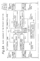
- FIG. 1A shows a general configuration of a duplexed loop LAN, in which a supervisory node (hereinafter SN) 1, which is a master station, and a plurality of interface nodes or communication nodes (hereinafter IN) 2-1 to 2-5 are connected by communication lines 3 which are constructed by #0 route and #1 route duplexed loop optical fiber cables.
- SN supervisory node
- IN interface nodes or communication nodes
- Each IN2-1 to 2-5 usually transmits/receives communication data mutually by using, for example, the route transmission line 3 as an active or hot system, and the #1 route transmission line as a standby system.
- Figure 1B and 1C are diagrams explaining transitions from an active route to a standby route when a fault occurs in the active route.
- Fig. 1B as an example, when a fault 4 such as breaking a line occurs in the transmission line 3 of the #0 route between IN 2-4 and IN 2-5, operation of the transmission line 3 is switched to the #1 route.
- Fig. 1C as an example when faults 5 occur in the transmission lines of both the #0 route and the #1 route, the network is reconstructed to continue the operation by a loop back from the transmission line of the #0 route to the transmission line of the #1 route (hereinafter loop back).
- the SN1 which is the master station, periodically receives control information giving the state of the transmission line 3 from each of the INs 2-1 to 2-5, to collectively control the state of the whole network.
- the SN 1 determines the state thereof and transmits control information to each INs 2-1 to 2-5 to control a not shown switch in each IN, so that the transmission line is switched between the #0 route and the #1 route, or a network is reconstructed by effecting a loop back. That is, each of the INs 2-1 to 2-5, which are slave stations, operated in accordance with an instruction from the SN 1, which is a master station.
- the supervisory node sequentially determines whether or not respective subsidiary or slave nodes (terminals) are normal, by interrogation commands, forming a loop back between predetermined nodes.
- a supervisory node transmits a loop back start command to respective subsidiary nodes simultaneously, and then the supervisory node transmits a loop-back reset command to each subsidiary node.
- the loop-back reset commands are received from both of the two transmission lines in each subsidiary node, the loop back is reset so that a loop back is formed between predetermined nodes.
- This control requires a smaller number of control steps than the control in the document (2).
- the node determines whether or not a normal signal has been input from respective transmission lines.
- the reset which can be considered by a person skilled in the art, may be carried out as follows.
- the SN 1 periodically receives control information from each of the INs 2-1 to 2-5 and then, in accordance with that information sequentially transmits control information to each of the INs 2-1 to 2-5. Therefore, to change the construction of the system, a complex control sequence involving several steps is necessary, which brings a problem of a long processing time.
- the present invention was created based on the above circumstances.
- the object of the present invention is to enable each communication node to independently or autonomously decide the state of the transmission line fault and so forth, so that an autonomous and rapid reconstruction of the network can be made by a simple distributed control.
- FIG. 2 is a block diagram explaining the basic concept of the present invention.
- a plurality of communication nodes 6-1, 6-2, 6-3 .... having data transmitting/receiving means 15-1, 15-2, 15-3 ..., such as data terminal equipment and so forth, are connected by duplexed loop transmission lines 7-1, 7-2 for transmitting data in reverse directions.
- These transmission lines are realized as LAN's(local area networks) constructed by, for example, optical fibers.
- control data 9-1, 9-2, ... indicating the connecting states of the respective transmission lines 7-1, 7-2 is input to frames 8-1, 8-2 ..., which are communication signals transmitted and received among respective communication nodes 6-1 ..., and transmitted through each transmission line 7-1, 7-2.
- Each of the communication nodes 6-1 ... has a control data separating means 10-1, 11-1, ... for detecting and separating, at a predetermined time interval, control data 9-1, 9-2 ... inserted to each frame, for example, 8-1, 8-2 ..., which is input from each transmission lines 7-1, 7-2 and further, has a transmission line switch control means 12-1, ... for switching the connecting state between each input/output 20-1, 21-1, ... of the transmission lines 7-1, 7-2 and the input/output 22-1, ... of the data transmission/receiving means 15-1, ..., based on each control data 16-1, 17-1 ... separated thereby, and still further, has a control data multiplexing means 13-1, 14-1 ...
- each control data multiplexing means 13-1, 14-1, ... receives this data so that the control data 9-3, 9-4, ... to be inserted to the transmitted frame 8-3, 8-4, ... is changed in accordance with a predetermined rule. Then, the frames 8-3, 8-4, ... are transmitted to the other communication nodes and the states therein are also changed.
- a network can be independently or autonomously without assistance and by the master station.
- the connecting state switching rule in the transmission line switching control means 12-1,... corresponding to the state change of the input control data 9-1 (16-1), ..., and the rule for changing the control data in the control data multiplexing means 13-1, 14-1,... corresponding to the change of the connecting state therein can be previously determined. Therefore, by storing these rules, for example, as tables, in each transmission line switching control means, the above-mentioned operation can be realized by effecting a simple control to shift to a new state with reference to the tables when the state is changed, so that a rapid reconstruction of a network is possible. Further, when the above-mentioned rules are realized by hardware such as a sequence circuit and so forth, an even higher speed control can be effected.
- the general configuration of the loop network which is the subject of the present invention is the same as that shown in Fig. 1A, and therefore, a description thereof is omitted.
- Figs. 3A and 3B are construction diagrams of an embodiment of the present invention.
- Fig. 3A shows the construction of a supervisory node SN1 (hereinafter master station), which has functional blocks of exactly the same construction, as shown by dash-dot lines 23, corresponding to each transmission line 3 of the #0 route and the #1 route.
- master station supervisory node SN1
- an optical signal input from the transmission line 3 of the #0 route is converted into an electrical signal in an optical/electrical converting circuit, i.e., an optical signal receiver (hereinafter OR) 29, and then input to a frame decomposition/data separation circuit (hereinafter DMX).
- an optical/electrical converting circuit i.e., an optical signal receiver (hereinafter OR) 29, and then input to a frame decomposition/data separation circuit (hereinafter DMX).
- control data (later described in more detail) is separated from a signal having a frame format input, as an electrical signal, is output from a read register (hereinafter RRG) 31 through a control line 31 to a central control unit (hereinafter CPU) 24, and the other data is input to switch part 26.
- RRG read register
- CPU central control unit
- communication data from the switch part 26 is input to a frame generating circuit (hereinafter MUX) 32 in which the data is multiplexed with control data input from the CPU 24 through a control line 36 and a write register (hereinafter WRG) 34, and further, after synchronization is established with a clock input from a generator 28, a frame signal is assembled and output to an electrical/optical converting circuit, i.e., an optical sending circuit (hereinafter OS) 33, and then, after being converted in the OS 33, to an optical signal, is output to the transmission line 33 of the #0 route.
- MUX frame generating circuit
- WRG write register
- the switch part 26 arbitrarily connects the inputs from the respective DMX's 30 of the #0 route and the #1 route and the input from a frame delay compensating circuit, in other words, a frame buffer memory (hereinafter FBM) 27 with the outputs of the respective MUX's 32 and the FBM 27.
- FBM 27 is used for compensating the delay of the frame signal (described later) transmitted through the transmission line 3.
- the CPU 24 changes the setting state of the switch part 26 based on the control data input through the control line 35 and outputs new control data through the control line 36.
- a main memory (hereinafter MM) 25 stores a program for carrying out the above-mentioned operation, and the tables (described later).
- Fig. 3B shows the construction of one of the communication nodes IN 2-1 to 2-5 (hereinafter slave station) which has basically the same function as the master station of Fig. 3A.
- the switch part 26′ (corresponding to 26 in Fig. 3A) is connected to a data processing circuit (packet handler) (hereinafter PHDR) 38.
- PHDR data processing circuit
- a not shown plurality of communication terminals are connected to the PHDR 38 through respective line set circuits (hereinafter LS).
- an OR 29′ in 23′ (corresponding to 23 in Fig. 3A) has, in addition to the function of the OR 29 in Fig. 3A, a function to extract clocks from the receiving signal.
- the extracted clocks are input through the DMX 30′ into the switch part 26′ .
- the switch part 26′ has, in addition to the function to arbitrarily connect the communication data input from the respective DMX's 30′ of the #0 route and the #1 route to the outputs of respective MUX's 32 and the outputs of the PHDR 38, a function to directly and arbitrarily connect the clock inputs (a part of the dash line group lc) from the respective DMX's 30′ of the #0 route and the #1 route to the clock outputs (a part of the dash line group lc) without passing through the PHDR 38.
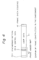
- Fig. 4 is a construction diagram of the frame signal transmitted through the transmitting line 3 of the #0 route and the #1 route. Roughly divided, it consists of a frame header part 40, user data 41, and a frame check sequence 42.
- the user data 41 is communication data transmitted/received between the terminals connected to different slave stations
- the frame check sequence 42 is a bit pattern for error detection and error correction for the transmitting frame.
- a frame identifying synchronous pattern 40-1 is inserted to the head part
- control data 40-2 which is the characterizing feature of the present invention, is also inserted therein. This will be described later.
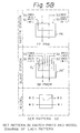
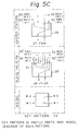
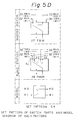
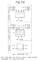
- Figs. 5A to 5E show the set patterns in the switch parts 26 of the master station; the middle portion of Figs. 5A to 5E show the set patterns in the switch part 26' of a slave station; and the lower portions in Figs. 5A to 5E are their corresponding model expressions.
- the difference between the master station and the slave station is that the slave station, as mentioned before, has the function for directly connecting the input from the DMX 30′ to the output of the MUX 32. This function, however, is not directly related to the present invention.
- the set pattern S1 in Fig. 5A shows a case in which the input and the output of the transmission line 3 of the #0 route are directly short circuited, and the input and the output of the transmission line 3 of the #1 route are respectively connected to the output and the input of the FBM 27 or the PHDR 38, so that the operation is carried out by the transmission line 3 of the #1 route.
- the set pattern S2 in Fig. 5B shows the case in which, contrary to the above case, the operation is carried out by the #0 route.
- the set pattern S3 in Fig. 5C shows the case in which the #1 route is short circuited and the #1 route is input to the FBM 27 or the PHDR 38, and the output thereof is output to the #0 route so that a loop back operation is carried out from the #1 route to the #0 route.
- the set pattern S4 in Fig. 5D shows the case in which, converse to the above, the #0 route is short circuited and the #0 route is input to the FBM 27 or the PHDR 38, and the output thereof is output to the #1 route so that the loop back operation is carried out from the #0 route to the #1 route.
- the set pattern S5 in Fig. 5E shows the case in which both the #0 route and the #1 route are short circuited, and thus that station is not used.
- the above-mentioned set patterns S1 to S5 are realized by the CPU 24 in Fig. 3A or 3B by controlling the switch part 26 or 26′ through the control line 37.
- the DMX 30 or 30′ of the #0 route and the #1 route in Fig. 3A or 3B separates only the control data 40-2 from the frame signal input with the format shown in Fig. 4 and inputs the data from the RRG 31 of each route through the control line 35 to the CPU 24.
- the control data output from the CPU 24 through each control line 36 and WRG 34 is inserted and transmitted by the MUX 32 of each route as control data 40-2 of the frame signal shown in Fig. 4.
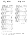
- the MM 25 has a table shown in Fig. 6A
- the MM25 has a table shown in Fig. 6B.
- the CPU 24 of the master station or the slave station accesses the MM25 in response to the aforementioned control data from the respective RRG's 31 by the #0 route and the #1 route, to refer to the table show in Fig. 6A or 6B, and first determines the set pattern of the switch 26 or 26′, to perform the control of the respective switches via the control line 37.
- the mark X in the input control data indicates that the respective DMX's 30 in the master station (Fig. 3A) or the respective DMX's 30′, in the slave station (Fig. 3B) did not receive the control data within a predetermined time. That is, the mark X indicates that the CPU 24 did not receive the control data within a predetermined time.
- the mark A in the control data input or output from or to the #0 route or the #1 route indicates that the route is an active route.
- the mark A′ in the control data input or output from or to the #0 route or the #1 route indicates that the route is a loop back route of an active route returned from any one of the master station or the slave stations.
- the mark B in the control data input or output from or to the #0 route or the #1 route indicates that the input route is a standby route.
- the mark B′ in the control data input or output from or to the #0 route or the #1 route indicates that the route is a loop back route of a standby route returned from any one of the master station or the slave station.
- the switch setting pattern S1, S2, S3, S4 or S5 in the master station or in each of the slave stations is determined by a permutation of two of the five marks A, B, A′, B′, and X in the input control data.
- the marks in the output control data on the #0 route and the #1 route from the master station or from each of the slave stations are determined by the combination of the input marks and the switch setting pattern.
- the marks A, B, A′, B′, and X constitute the control data in the frame format shown in Fig. 4. Therefore, in the following, the marks are referred to as the control data.
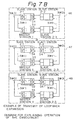
- a practical control operation using the above-mentioned tables will be described with reference to the practical example shown in Fig. 7A and 7B.
- Figure 7A shows an example of a change from the #0 route operation to a loop back operation.
- a loop network (corresponding to Fig. 1A) consisting of the master station (SN) 1 and the slave station (IN) 2-1 to 2-3 is provided, and when a fault 45 has not yet occurred, the setting of the switch in each station is assumed to be fixed to the pattern S2 shown in Fig. 5B so that the operation is carried out by the #0 route, then the control data A is input to the inputs of the #0 routes of the respective stations, and the control data B is input to the inputs of the #1 routes.
- each station outputs the control data A, which is the same as the input control data A from the #0 route, to the #0 output route, and outputs the control data B, which is the same as the input control data B from the #1 route, to the #1 output route, as can be seen from the tables shown in Figs. 6A and 6B.
- the state is changed to the state shown by the dash line 44. That is, first, in the slave station 2-2, the control data A is input to the input from the #0 route, but the control data is not input to the input from the #1 route. Therefore, with reference to the third column from the top in the table of Fig. 6B, the switch setting is changed to the state S4 shown in Fig. 5D so that a loop back operation from the #0 route to the #1 route is carried out in the slave station 2-2. Simultaneously, the control data A is output to the output of the #0 route and the control data A′, is output to the output of the #1 route.
- the control data A is input to the input of the #0 route, and the control data A′ is input to the input of the #1 route.
- the switch setting is kept at the pattern S2 of Fig. 5B without change, so that the control data A is output to the #0 route and the control data A, is output to the #1 route.
- the control data B is input to the input of the #1 route and the control data is not input to the input of the #0 route. Accordingly, since the input data permutation is "XB", referring to the tenth column of the table shown in Fig. 6B, the switch setting changes to the pattern S3 shown in Fig. 5C so that the loop back operation from the #1 route to the #0 route is carried out. In this case, the control data B′ is output to the #0 route and the control data B is output to the #1 route.
- the switch setting is kept at the pattern S2 as shown in Fig. 5B, as can be seen from the tenth column of the table shown in Fig. 6A so that the control data A is output from the output of the #0 route and the control data B is output from the output of the #1 route.
- each station performs its own distributed control to change to the state as shown by dash line 44, so that the transmission lines 3 of the slave stations 2-2 and 2-3 are looped back, to reconstruct the network.
- Figure 7B shows an example of a loop back expansion.
- the switch setting is the pattern S4 as shown in Fig. 5D, so that the loop back operation from the #0 route to the #1 route is carried out at the slave station 2-1 and the control data A is output from the output of the #0 route and the control data A, is output from the output of the #1 route.
- the control data A′ is input to the input of the #1 route and no control data is input to the input of the #0 route. Therefore, as can be seen from the fourteenth column in the table shown in Fig. 6A, the switch setting in the master station becomes as shown by the pattern S3 of Fig. 5C. As a result, a loop back operation from the #1 route to the #0 route is performed so that the control data A is output from the output of the #0 route and the control data B is output from the output of the #1 route.
- the whole state changes from that of the dash line 47 to that of the dash line 48. That is, in the slave station 2-1, the control data A is input to the input of the #0 route as in the state of the dash line 46, but the control data A′ is input to the input of the #1 route. Accordingly, with reference to the table of Fig. 6B, the switch setting changes to the pattern S2 shown in Fig. 5B so that the operation is expanded from the loop back in the slave station 2-1 to the loop back in the slave station 2-2. As a result, at the slave station 2-2, the control data A is output from the output of the #0 route and the control data A′ is output from the output of the #1 route.
- the slave station 2-1 autonomously performs its own distributed control to change to the state shown by the dash line 48, so that the loop back interval is expanded automatically from the slave station 2-1 to the slave station 2-2 and the network is reconstructed.
- the tables of Fig. 6A and 6B cover all cases of changing the setting of the switch part 26 or 26′ , and what kind of control data should be output to each WRG 34, based on the control data input from the RRG 31 of each system.
- the CPU 24 of each system performs the distributed control based on the above mentioned table stored in the MM 25, so that an appropriate automatic reconstruction of a network can be effected in all cases in which the state of each node (station) is changed.
- the CPU 24 performs the distributed control based on the tables stored in the MM 25, but the change of the state of the table shown in Fig. 6A or 6B may be realized by hardware constructed by a sequence circuit and so forth. In this case, the distributed control can be performed at a higher speed.
- the switch rule of the connecting state of the transmission line corresponding to a change of the state of the input control data, and the changing rule of the output control data corresponding to the change of the connecting state can be previously determined in one means. Therefore, by realizing these rules by reference tables or sequence circuits and so forth, a very simple and high speed distributed control can be performed.
Landscapes
- Engineering & Computer Science (AREA)
- Computer Networks & Wireless Communication (AREA)
- Signal Processing (AREA)
- Small-Scale Networks (AREA)
Claims (13)
- Duplexsystem von Übertragungsleitungen in einem Schleifennetzwerk, bei dem eine Vielzahl von Kommunikationsknoten (6-1 ...), von denen jeder Datenübertragungs-/Datenempfangseinrichtungen (15,-1 ...) aufweist, durch Duplexschleifen-Übertragungsleitungen (7-1, 7-2) zum Übertragen von Daten in umgekehrten Richtungen verbunden sind,- wobei jeder Kommunikationsknoten normalerweise so konfiguriert ist, daß er die Übertragungsleitungen passieren läßt, und wobei er
gekennzeichnet ist durch:- Rückschleifeneinrichtungen zur Durchführung einer Rückschleifenoperation als Antwort auf einen vorbestimmten Zustand von Signalen, die durch benachbarte Knoten in jeder Richtung der Duplexschleifenübertragungsleitungen ausgelöst werden; und- Rückleitungsangabeeinrichtungen (13-1, 14-1) zum Hinzufügen einer Rückanzeige zum Ausgangssignal, wonach ein empfangenes Signal zurückgesandt wurde, wenn das empfangene Signal den Knoten nicht durchlaufen konnte;- so daß als Antwort auf das aus den beiden Richtungen empfangene Signal jeder der Kommunikationsknoten (6-1 ...) autonom die Rückschleifenoperation durchführt oder freigibt. - Duplexsystem nach Anspruch 1,
bei dem einer der Kommunikationsknoten ein Überwachungsknoten ist, der eine Aktivangabeeinrichtung/Bereitschaftsangabeeinrichtung aufweist, um den in die zwei Richtungen der Duplexübertragungsleitungen (7-1, 7-2)) zu übertragenen Sendesignalen Aktiv-Bereitschaftsangaben hinzuzufügen, wonach jede der beiden Richtungen ein aktiver Leitweg oder ein Bereitschaftsleitweg ist. - Duplexübertragungsleitungssystem in einem Schleifennetzwerk, bei dem eine Vielzahl von Kommunikationsknoten (6-1 ...), von denen jeder Datenübertragungs-/Datenempfangseinrichtungen (15,-1 ...) aufweist, durch Duplexschleifenübertragungsleitungen (7-1, 7-2) zum Übertragen von Daten in umgekehrten Richtungen verbunden sind,
gekennzeichnet durch:- Einrichtungen zum Einfügen von Steuerdaten (13-1, 14-1 ...), die den Anschlußzustand jeder Übertragungsleitung (7-1, 7-2) an jeden Datenblock (8-1, 8-2 ...) anzeigen, der durch jede Übertragungsleitung übertragen wird,- wobei das System in jedem Kommunikationsknoten aufweist:- Steuerdatentrenneinrichtungen (10-1, 11-1) zum Erfassen und Trennen von Steuerdaten in einem vorbestimmten Zeitintervall, die in jeden Datenblock (8-1, 8-2 ...) eingefügt sind, der von jeder Übertragungsleitung eingegeben wird; Übertragungsleitungsschaltsteuereinrichtungen (12-1 ...) zum Durchschalten des Anschlußzustandes zwischen jedem Eingang/Ausgang jeder Übertragungsleitung und dem Eingang/Ausgang der Datenübertragungs-/Datenempfangseinrichtungen auf der Basis der von jeder Steuerdatentrenneinrichtung getrennten Steuerdaten; und Steuerdatenmultiplexierungseinrichtungen (13-1, 14-1) zum Multiplexen neuer Steuerdaten auf jeden an jede Übertragungsleitung zu übertragenden Datenblock auf der Basis des Anschlußzustandes; so daß durch verteiltes Steuern jedes Kommunikationsknotens (6-1, 6-2 ...) eine Steuerung entsprechend der Änderung des Zustandes des Netzwerkes durchgeführt wird. - Duplexsystem nach Anspruch 1 oder 3, bei dem die zwei Richtungen jeweils als #0-Leitweg und als #1-Leitweg angenommen werden, wobei jeder der Kommunikationsknoten eine Schalteinrichtung (12-1, 12-2 ...) zum Umschalten zwischen den beiden Richtungen der Duplexübertragungsleitungen (7-1, 7-2) als Antwort auf die Aktiv-Bereitsschaftsangaben der vom #0-Leitweg und vom #1-Leitweg empfangenen Signale aufweist.
- Duplexsystem nach Anspruch 4, bei dem die beiden Richtungen als #0-Leitweg bzw. als #1-Leitweg angenommen werden, wobei der Überwachungsknoten eine Schalteinrichtung (12-1) zum Umschalten zwischen den beiden Richtungen der Duplexübertragungsleitungen aufweist, als Antwort auf die aktiven Angaben/Bereitsschaftsangaben der vom #0-Leitweg und vom #1-Leitweg empfangenen Signale.
- Duplexsystem nach Anspruch 1 oder 4, bei dem die beiden Richtungen als #0-Leitweg bzw. als #1-Leitweg angenommen werden;- wobei jeder Kommunikationsknoten (6-1, 6-2 ...) aufweist:- eine Schalteinrichtung (26, 26') zum Umschalten der Verbindung vom #0-Leitweg zum #1-Leitweg, und vom #1-Leitweg zum #0-Leitweg; und- eine Steuereinrichtung (24) zum Steuern der Schalteinrichtung auf der Basis der Aktiv-Bereitschaftsangaben in den vom #0-Leitweg bzw. vom #1-Leitweg empfangenen Signalen:
- Duplexsystem nach Anspruch 6, wobei die Rückleitungsangabeeinrichtungen (13-1, 14-1) in jedem Kommunikationsknoten eine Einrichtung aufweist, die zum Hinzufügen der Rückleitungsangabe an ein zurückgeleitetes Signal dient, wenn dies das Ergebnis eines Eingriffs durch die Schalteinrichtung ist.
- Duplexsystem nach Anspruch 7, bei dem die Steuereinrichtung (24) in jedem Kommunikationsknoten eine Datentabelle zum Speichern eines Steuermusters zum Ansteuern der Schalteinrichtung aufweist;- wobei das Steuermuster vier Arten von Empfangsmustern, bestehend aus einem aktiven Muster/Bereitschaftsmuster und einem aktiven Rückleitungsmuster/Bereitschaftsrückleitungsmuster in dem vom #0-Leitweg empfangenen Signal aufweist; und weiter- ein Steuermuster aufweist, das vier Arten von Empfangsmustern umfaßt, bestehend aus einem aktiven Muster/Bereitschaftsmuster und einem aktiven Rückleitungsmuster/Bereitschaftsrückleitungsmuster in dem vom #1-Leitweg empfangenen Signal.
- Duplexsystem nach Anspruch 8, wobei:- jeder Kommunikationsknoten eine Rückschleifenfreigabeeinrichtung (24) zum automatischen oder autonomen Freigeben der Rückschleifenoperation aufweist, wenn der Knoten ein vorbestimmtes Muster in den aus beiden Richtungen empfangenen Signalen empfängt.
- Duplexsystem nach Anspruch 1 oder 4, bei dem:- die Kommunikationsknoten einen Überwachungsknoten (1) und Endstationsknoten (2-1, 2-2 ...) aufweisen,- wobei der Überwachungsknoten eine Aktivangabeneinrichtung/Bereitsschaftsangabeneinrichtung zum Hinzufügen von Aktiv-Bereitschaftsangaben zu den an die beiden Richtungen der Duplexübertragungsleitungen zu übertragenden Sendesignale aufweist, wonach jede der beiden Richtungen ein aktiver Leitweg oder ein Bereitschaftsleitweg ist; und- wobei im Falle, daß die beiden Richtungen als #0-Leitweg bzw. als #1-Leitweg angesehen werden, jeder der Endstationsknoten eine Schalteinrichtung (26') zum Umschalten zwischen den beiden Richtungen der Duplexübertragungsleitungen als Antwort auf die aktiven Angaben/Bereitschaftsangaben der vom #0-Leitweg und vom #1-Leitweg empfangenen Signale aufweist.
- Duplexsystem nach Anspruch 10, wobei:- der Überwachungsknoten eine Schalteinrichtung (26) zum Umschalten zwischen den beiden Richtungen der Duplexübertragungsleitungen als Antwort auf die aktiven Angaben/Bereitschaftsangaben der vom #0-Leitweg und vom #1-Leitweg empfangenen Signale aufweist; und wobei die Endstationsknoten eine Schalteinrichtung (26') zum Umschalten des Anschlusses vom #0-Leitweg auf den #1-Leitweg und vom #1-Leitweg auf den #0-Leitweg aufweist; und wobei eine Steuereinrichtung (24) zum Steuern der Schalteinrichtung auf der Basis der Aktiv-Bereitschaftsangaben in den vom #0-Leitweg bzw. #1-Leitweg empfangenen Signale aufweist.
- Duplexsystem nach Anspruch 10 oder 11, wobei:- jeder Endstationsknoten (2-1, 2-2 ...) eine Einrichtung zum Hinzufügen der Rückleitungsangabe zu einem zurückgeleiteten Signal aufweist, wenn dies das Ergebnis eines Eingriffs durch die Schalteinrichtung ist; und- wobei die Steuereinrichtung (24) jeweils in jedem Endstationsknoten und im Überwachungsknoten Datentabellen zum Speichern eines Steuermusters enthalten, die zum Ansteuern der Schalteinrichtungen dienen;- wobei das Steuermuster vier Arten von Empfangsmustern umfaßt, bestehend aus einem Aktivmuster/Bereitschaftsmuster und einem Aktivrückleitungsmuster/Bereitsschaftsrückleitungsmuster in dem vom #0-Leitweg empfangenen Signal; und- wobei das Steuermuster vier Arten von Empfangsmustern umfaßt, bestehend aus einem Ativmuster/Bereitschaftsmuster und einem Aktivrückleitungsmuster/Bereitsschaftsrückleitungsmuster in dem vom #1-Leitweg empfangenen Signal.
- Duplexsystem nach Anspruch 12, wobei:- jeder Kommunikationsknoten eine Rückschleifenfreigabeeinrichtung zum automatischen Freigeben der Rückschleifenoperation aufweist, wenn ein von der Rückleitungsoperation betroffener Knoten in jedem Endstationsknoten oder im Überwachungsknoten ein vorbestimmtes Muster in den aus den beiden Richtungen empfangenen Signalen empfängt.
Applications Claiming Priority (2)
| Application Number | Priority Date | Filing Date | Title |
|---|---|---|---|
| JP62320134A JPH0752886B2 (ja) | 1987-12-19 | 1987-12-19 | ループ型ネットワークの構成方法 |
| JP320134/87 | 1987-12-19 |
Publications (3)
| Publication Number | Publication Date |
|---|---|
| EP0321907A2 EP0321907A2 (de) | 1989-06-28 |
| EP0321907A3 EP0321907A3 (en) | 1990-04-25 |
| EP0321907B1 true EP0321907B1 (de) | 1993-12-01 |
Family
ID=18118085
Family Applications (1)
| Application Number | Title | Priority Date | Filing Date |
|---|---|---|---|
| EP88121237A Expired - Lifetime EP0321907B1 (de) | 1987-12-19 | 1988-12-19 | Zweiadriges Datenübertragungssystem mit Duplexbetrieb für ein ringförmiges Netzwerk |
Country Status (5)
| Country | Link |
|---|---|
| US (1) | US4930119A (de) |
| EP (1) | EP0321907B1 (de) |
| JP (1) | JPH0752886B2 (de) |
| CA (1) | CA1323081C (de) |
| DE (1) | DE3886022T2 (de) |
Families Citing this family (23)
| Publication number | Priority date | Publication date | Assignee | Title |
|---|---|---|---|---|
| JP2713605B2 (ja) * | 1989-06-17 | 1998-02-16 | 富士通株式会社 | リングネットワーク切替制御方式 |
| DE69128172T2 (de) * | 1990-01-26 | 1998-04-02 | Fujitsu Ltd | Kommunikationssystem zwischen lokalen netzwerken mit unterschiedlichen geräten |
| US5285448A (en) * | 1990-03-01 | 1994-02-08 | Hitachi, Ltd. | Transmission system of system of system control information in a ring LAN system |
| US5199025A (en) * | 1990-04-20 | 1993-03-30 | Matsushita Electric Industrial Co., Ltd. | Loop back method for loop type lan transmission line |
| JP2784080B2 (ja) | 1990-05-09 | 1998-08-06 | 富士通株式会社 | リングネットワーク及びその障害復旧方法並びにリングネットワークに用いられるノード |
| US5060226A (en) * | 1990-07-05 | 1991-10-22 | Phoenix Microsystems, Inc. | Telecommunications network test system |
| JP2578704B2 (ja) * | 1991-03-26 | 1997-02-05 | 日本電信電話株式会社 | リング伝送網のループバック方法およびリング伝送装置 |
| CA2072171A1 (en) * | 1991-06-24 | 1992-12-25 | Kaori Kishi | Clock recovery system capable of automatically switching a direction of a clock pulse sequence from one to another |
| JPH0591119A (ja) * | 1991-09-27 | 1993-04-09 | Fujitsu Ltd | Sdh伝送装置 |
| AU672212B2 (en) * | 1992-08-26 | 1996-09-26 | Minitronics Pty. Limited | Improved emergency lighting system |
| AU690467B2 (en) * | 1992-08-26 | 1998-04-23 | Minitronics Pty. Limited | Improved emergency lighting system |
| AU690466B2 (en) * | 1992-08-26 | 1998-04-23 | Minitronics Pty. Limited | Improved emergency lighting system |
| US5406401A (en) * | 1992-10-02 | 1995-04-11 | At&T Corp. | Apparatus and method for selective tributary switching in a bidirectional ring transmission system |
| GB9225081D0 (en) * | 1992-12-01 | 1993-01-20 | Plessey Telecomm | Dual connections |
| JPH07177202A (ja) * | 1993-12-21 | 1995-07-14 | Mitsubishi Electric Corp | 通信制御装置 |
| JP2827936B2 (ja) * | 1994-12-13 | 1998-11-25 | 日本電気株式会社 | ディジタル通信網 |
| DE19509558A1 (de) * | 1995-03-16 | 1996-09-19 | Abb Patent Gmbh | Verfahren zur fehlertoleranten Kommunikation unter hohen Echtzeitbedingungen |
| US6766482B1 (en) | 2001-10-31 | 2004-07-20 | Extreme Networks | Ethernet automatic protection switching |
| US7110356B2 (en) * | 2001-11-15 | 2006-09-19 | Fujitsu Limited | Pre-provisioning a light path setup |
| US20050147027A1 (en) * | 2002-08-30 | 2005-07-07 | Nokia Corporation | Method, system and hub for loop initialization |
| JP4088246B2 (ja) | 2003-12-05 | 2008-05-21 | 富士通株式会社 | リングネットワークのマスタ設定方法及び装置 |
| EP2397832A3 (de) | 2010-06-21 | 2016-12-21 | Horiba, Ltd. | Automatische Drehmomentkalibrierungsvorrichtung |
| CA2966704A1 (en) * | 2014-11-19 | 2016-05-26 | Lantiq Beteiligungs-GmbH & Co.KG | Physical medium dependent layer bonding |
Family Cites Families (12)
| Publication number | Priority date | Publication date | Assignee | Title |
|---|---|---|---|---|
| JPS58175335A (ja) * | 1982-04-07 | 1983-10-14 | Hitachi Ltd | ル−プ式デ−タ伝送システムのル−プバツク制御方法 |
| JPS5940739A (ja) * | 1982-08-30 | 1984-03-06 | Fujitsu Ltd | ル−プパツク制御方式 |
| JPS5950639A (ja) * | 1982-09-16 | 1984-03-23 | Hitachi Ltd | ル−プ式デ−タ伝送システムの障害回復検出方法 |
| BE895438A (nl) * | 1982-12-22 | 1983-06-22 | Bell Telephone Mfg | Communicatiestelsel met meerdere ringen |
| US4593154A (en) * | 1983-07-08 | 1986-06-03 | Nissan Motor Company, Limited | Loop-type data transmission/reception network |
| JPH0614643B2 (ja) * | 1983-12-05 | 1994-02-23 | 株式会社日立製作所 | ル−プ式デ−タ伝送システムの障害回復検出方法 |
| JPS60197045A (ja) * | 1984-03-21 | 1985-10-05 | Toshiba Corp | ル−プ接続制御方式 |
| US4683563A (en) * | 1984-10-11 | 1987-07-28 | American Telephone And Telegraph Company, At&T Bell Laboratories | Data communication network |
| US4648088A (en) * | 1985-08-19 | 1987-03-03 | Rockwell International Corporation | Distributed control time division multiplex ring communication apparatus |
| JPS62239739A (ja) * | 1986-04-11 | 1987-10-20 | Nec Corp | ル−プバツク箇所検出方式 |
| JPS6460026A (en) * | 1987-08-31 | 1989-03-07 | Fujitsu Ltd | Transmission line switching device for communication equipment |
| US4835763A (en) * | 1988-02-04 | 1989-05-30 | Bell Communications Research, Inc. | Survivable ring network |
-
1987
- 1987-12-19 JP JP62320134A patent/JPH0752886B2/ja not_active Expired - Fee Related
-
1988
- 1988-12-12 CA CA000585664A patent/CA1323081C/en not_active Expired - Fee Related
- 1988-12-19 DE DE88121237T patent/DE3886022T2/de not_active Expired - Fee Related
- 1988-12-19 EP EP88121237A patent/EP0321907B1/de not_active Expired - Lifetime
- 1988-12-19 US US07/286,614 patent/US4930119A/en not_active Expired - Lifetime
Also Published As
| Publication number | Publication date |
|---|---|
| JPH01164146A (ja) | 1989-06-28 |
| EP0321907A3 (en) | 1990-04-25 |
| EP0321907A2 (de) | 1989-06-28 |
| DE3886022D1 (de) | 1994-01-13 |
| JPH0752886B2 (ja) | 1995-06-05 |
| US4930119A (en) | 1990-05-29 |
| CA1323081C (en) | 1993-10-12 |
| DE3886022T2 (de) | 1994-05-05 |
Similar Documents
| Publication | Publication Date | Title |
|---|---|---|
| EP0321907B1 (de) | Zweiadriges Datenübertragungssystem mit Duplexbetrieb für ein ringförmiges Netzwerk | |
| US4709365A (en) | Data transmission system and method | |
| EP0242117B1 (de) | Steuerung von verteilten Taktimpulsen in einer verteilten Digital-Vermittlungsanlage | |
| US4733391A (en) | Communication networks | |
| JPH05316136A (ja) | シリアル通信網の故障分離及びバイパス再構成装置 | |
| JPH05316135A (ja) | デュアル・リング再構成装置 | |
| JPH0351142B2 (de) | ||
| JPH05300163A (ja) | シリアル通信網トポロギ情報生成方法及び装置 | |
| JP2001186159A (ja) | リング伝送システム及びそのスケルチ方法 | |
| JPH03204258A (ja) | 通信システム | |
| US7660237B2 (en) | Synchronous clock supply system and synchronous clock supply method | |
| JPH0621955A (ja) | クロック供給切替え方式 | |
| JP3952387B2 (ja) | ネットワーク処理装置及び設定方法 | |
| JP3331451B2 (ja) | ディジタル信号伝送装置 | |
| KR950005142B1 (ko) | 분산 노드 교환 시스템의 클럭 동기 제어 방법 | |
| JPH0430218B2 (de) | ||
| JP2679506B2 (ja) | クロック切替方式 | |
| JPH07112204B2 (ja) | ル−プ状ネツトワ−クシステムの伝送装置 | |
| KR200229642Y1 (ko) | 디지털중계선보드의클럭위상동기장치 | |
| JPS59183553A (ja) | ル−プ伝送方式 | |
| JPH0720121B2 (ja) | リング網での障害箇所の検出方法 | |
| JPH11261615A (ja) | 二重ループ型データ伝送装置 | |
| JPS63316956A (ja) | リングネットワ−ク通信装置における分散障害復旧制御装置 | |
| JPH05268235A (ja) | 2重ループ型通信装置の伝送路制御方式 | |
| JPH02100440A (ja) | ループ式伝送装置の親局設定方式 |
Legal Events
| Date | Code | Title | Description |
|---|---|---|---|
| PUAI | Public reference made under article 153(3) epc to a published international application that has entered the european phase |
Free format text: ORIGINAL CODE: 0009012 |
|
| AK | Designated contracting states |
Kind code of ref document: A2 Designated state(s): DE FR GB |
|
| PUAL | Search report despatched |
Free format text: ORIGINAL CODE: 0009013 |
|
| AK | Designated contracting states |
Kind code of ref document: A3 Designated state(s): DE FR GB |
|
| 17P | Request for examination filed |
Effective date: 19900419 |
|
| 17Q | First examination report despatched |
Effective date: 19920820 |
|
| GRAA | (expected) grant |
Free format text: ORIGINAL CODE: 0009210 |
|
| AK | Designated contracting states |
Kind code of ref document: B1 Designated state(s): DE FR GB |
|
| REF | Corresponds to: |
Ref document number: 3886022 Country of ref document: DE Date of ref document: 19940113 |
|
| ET | Fr: translation filed | ||
| PLBE | No opposition filed within time limit |
Free format text: ORIGINAL CODE: 0009261 |
|
| STAA | Information on the status of an ep patent application or granted ep patent |
Free format text: STATUS: NO OPPOSITION FILED WITHIN TIME LIMIT |
|
| 26N | No opposition filed | ||
| PGFP | Annual fee paid to national office [announced via postgrant information from national office to epo] |
Ref country code: FR Payment date: 19981209 Year of fee payment: 11 |
|
| PGFP | Annual fee paid to national office [announced via postgrant information from national office to epo] |
Ref country code: GB Payment date: 19981224 Year of fee payment: 11 |
|
| PGFP | Annual fee paid to national office [announced via postgrant information from national office to epo] |
Ref country code: DE Payment date: 19981229 Year of fee payment: 11 |
|
| PG25 | Lapsed in a contracting state [announced via postgrant information from national office to epo] |
Ref country code: GB Free format text: LAPSE BECAUSE OF NON-PAYMENT OF DUE FEES Effective date: 19991219 |
|
| GBPC | Gb: european patent ceased through non-payment of renewal fee |
Effective date: 19991219 |
|
| PG25 | Lapsed in a contracting state [announced via postgrant information from national office to epo] |
Ref country code: FR Free format text: LAPSE BECAUSE OF NON-PAYMENT OF DUE FEES Effective date: 20000831 |
|
| PG25 | Lapsed in a contracting state [announced via postgrant information from national office to epo] |
Ref country code: DE Free format text: LAPSE BECAUSE OF NON-PAYMENT OF DUE FEES Effective date: 20001003 |
|
| REG | Reference to a national code |
Ref country code: FR Ref legal event code: ST |