EP0320772B1 - Procédé pour la commutation hybride de paquets et dispositifs à cet effet - Google Patents
Procédé pour la commutation hybride de paquets et dispositifs à cet effet Download PDFInfo
- Publication number
- EP0320772B1 EP0320772B1 EP88120438A EP88120438A EP0320772B1 EP 0320772 B1 EP0320772 B1 EP 0320772B1 EP 88120438 A EP88120438 A EP 88120438A EP 88120438 A EP88120438 A EP 88120438A EP 0320772 B1 EP0320772 B1 EP 0320772B1
- Authority
- EP
- European Patent Office
- Prior art keywords
- packets
- switching
- subpackets
- packet
- frame
- Prior art date
- Legal status (The legal status is an assumption and is not a legal conclusion. Google has not performed a legal analysis and makes no representation as to the accuracy of the status listed.)
- Expired - Lifetime
Links
- 238000000034 method Methods 0.000 title claims abstract description 16
- 230000015654 memory Effects 0.000 claims abstract description 77
- 230000001360 synchronised effect Effects 0.000 claims abstract description 19
- 230000000737 periodic effect Effects 0.000 claims 4
- 230000001934 delay Effects 0.000 abstract description 5
- 230000008878 coupling Effects 0.000 description 32
- 238000010168 coupling process Methods 0.000 description 32
- 238000005859 coupling reaction Methods 0.000 description 32
- 230000005540 biological transmission Effects 0.000 description 7
- 238000010586 diagram Methods 0.000 description 6
- 238000005516 engineering process Methods 0.000 description 5
- 238000004891 communication Methods 0.000 description 3
- 238000003780 insertion Methods 0.000 description 2
- 230000037431 insertion Effects 0.000 description 2
- 238000012545 processing Methods 0.000 description 2
- 238000012546 transfer Methods 0.000 description 2
- 230000000694 effects Effects 0.000 description 1
- 230000006870 function Effects 0.000 description 1
- 230000007257 malfunction Effects 0.000 description 1
- 230000008707 rearrangement Effects 0.000 description 1
- 230000000717 retained effect Effects 0.000 description 1
- 238000004904 shortening Methods 0.000 description 1
Images


Classifications
-
- H—ELECTRICITY
- H04—ELECTRIC COMMUNICATION TECHNIQUE
- H04L—TRANSMISSION OF DIGITAL INFORMATION, e.g. TELEGRAPHIC COMMUNICATION
- H04L12/00—Data switching networks
- H04L12/54—Store-and-forward switching systems
- H04L12/56—Packet switching systems
- H04L12/5601—Transfer mode dependent, e.g. ATM
-
- H—ELECTRICITY
- H04—ELECTRIC COMMUNICATION TECHNIQUE
- H04L—TRANSMISSION OF DIGITAL INFORMATION, e.g. TELEGRAPHIC COMMUNICATION
- H04L12/00—Data switching networks
- H04L12/64—Hybrid switching systems
-
- H—ELECTRICITY
- H04—ELECTRIC COMMUNICATION TECHNIQUE
- H04J—MULTIPLEX COMMUNICATION
- H04J2203/00—Aspects of optical multiplex systems other than those covered by H04J14/05 and H04J14/07
- H04J2203/0001—Provisions for broadband connections in integrated services digital network using frames of the Optical Transport Network [OTN] or using synchronous transfer mode [STM], e.g. SONET, SDH
- H04J2203/0003—Switching fabrics, e.g. transport network, control network
- H04J2203/0005—Switching elements
-
- H—ELECTRICITY
- H04—ELECTRIC COMMUNICATION TECHNIQUE
- H04L—TRANSMISSION OF DIGITAL INFORMATION, e.g. TELEGRAPHIC COMMUNICATION
- H04L12/00—Data switching networks
- H04L12/54—Store-and-forward switching systems
- H04L12/56—Packet switching systems
- H04L12/5601—Transfer mode dependent, e.g. ATM
- H04L2012/5638—Services, e.g. multimedia, GOS, QOS
- H04L2012/5646—Cell characteristics, e.g. loss, delay, jitter, sequence integrity
- H04L2012/5649—Cell delay or jitter
Definitions
- the invention relates to a method for switching messages broken down into packets of uniform length according to the preamble of the main claim and devices therefor.
- the increasing variety of telecommunications services requires a very flexible switching system. Fast packet switching systems are particularly considered for this; the data is transmitted in packets. In such systems, delays, runtime fluctuations and packet losses cannot be completely ruled out.
- the individual telecommunications services are susceptible to this in different ways. For example, data services that detect packet loss and can request that packet again are against packet loss far less susceptible than voice or moving image services, which have to evaluate the incoming information immediately (electro-acoustic or electro-optical implementation) and where losses and delay fluctuations (delay jitter) lead to malfunctions.
- a packet inevitably contains significantly more bits than a time slot in conventional time division technology.
- frames with 32 time slots of 16 bits each i.e. with 512 bits common. Since a complete frame must be buffered per input in each time switching stage when switching in synchronous time multiple technology, the memory requirement increases considerably. Delays of the order of magnitude of a frame also occur in each case. If, as expected, the frame repetition frequency is the same in both cases (8 kHz), then the memories not only have to be considerably larger, but also faster to the same extent. A speed reduction by parallel instead of serial processing is at most possible to a very limited extent.
- the invention is based on the object of designing a hybrid packet switching method of the type mentioned in such a way that the need for fast memories is reduced in order to carry it out, and of specifying the facilities required for this.
- all packets within the switching center are broken down into packet parts of the same length and subframes divided up.
- the mediation is based on the subframe. Delays and space requirements within the switching network are reduced in the frame: subframe ratio.
- the speed within the coupling arrangement is retained.
- a sorter is required for each input and each output line, which has to cache one frame each.
- slower memories can be used here than in the coupling stages. Even with a three-stage coupling arrangement, not only the number of fast memories required, but the overall memory requirement is reduced.
- the basic idea of the invention is that the division of the packets into packet parts effectively results in shorter "packets", which also result in a correspondingly lower memory requirement.
- the individual parts of the packet are not inserted into the data stream at a random location, as is customary for packets, but rather by following one another in accordance with a predetermined pattern, STM cells and ATM cells preferably being treated differently.
- parts of the package that belong together must not follow one another directly, rather they must alternate with package parts of other packages.
- the invention is described in terms that are primarily applied to spatially concentrated switching devices.
- the following exemplary embodiment also represents a concentrated switching device.
- the present invention is equally applicable to non-concentrated switching devices, for example ring systems.
- reference is made on the one hand to the article mentioned at the beginning from “Der Fernmelde Ingenieur”, where bus and ring systems under 4.1.2 are subordinate to the coupling arrangements under 4, and on the other hand to the publication EP-A2 0 125 744, "Closed loop telecommunication system ", in which a ring system is described in which a complete frame with a large number of packets always rotates, for which purpose shift registers or other memories are required.
- the PRELUDE project of the CNET (Center National d'Etudes des Telecommunications) in France is one of the first and best-known switching centers for fast packet switching.
- a description can be found, for example, in IEEE International Conference on Communications '87, vol. 2, June 1987, IEEE New York US, pages 769-773; J. Coudreuse et al .: "PRELUDE: AN ASYNCHRONOUS TIME-DIVISION SWITCHED NETWORK".
- the incoming packets are actually also divided into a number of packet parts, which are then switched to the exit of the exchange.
- a super multiplexing takes place on the input side; that is, the message streams of all inputs are combined into a single message stream.
- This super-multiplex message stream is written into a buffer, read out again in a different order and distributed to the various outputs by demultiplexing.
- the packet parts of a packet are distributed over different lines in the manner of parallel processing (here, however, staggered in time). Larger, multi-level exchanges can hardly be realized in this way.
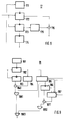
- FIG. 1 showing the treatment of those packets which are to be treated preferentially
- FIG. 2 shows the treatment of the other packets more closely.
- a frame is assumed that contains six packets of eight octets each (8 bits each).
- positions 1, 3 and 6 contain packets, PS1, PS2 and PS3, which are to be switched in a packet-switching manner.
- positions 2 and 4 there are packets, CS1 and CS2, which are to be switched through in a circuit-switching manner.
- Position 5 contains a control package DP or an empty package LP.
- Each packet consists of a message part (payload) P and a preceding label (header, label).
- the brand is information for the next exchange, the incoming brand HE is therefore initially replaced by an outgoing brand HA.
- an internal Hi label which is used to differentiate between the types of packages and contains connection-specific information.
- the incoming packets (first line in FIGS. 1 and 2) are now stored with the partially modified, HA, partially added brand parts, Hi (second line in FIGS. 1 and 2). It is then output in a different order (third line in FIGS. 1 and 2). The output is staggered in time, but is not offset in the display.
- the frame is divided into 8 subframes, each with six octets.
- the packets CS1 and CS2 to be treated with preference are now switched through in a synchronous manner, and are therefore referred to as STM cells.
- STM cells Each STM cell is assigned an octet within the same position in each subframe, so that the STM cell CS1 in the second position is assigned is octetally divided into the second positions of the subframes.
- the fourth positions are correspondingly assigned to the STM cell CS2.
- the assignment between the whole package in the frame and the package parts in the subframe can also be done differently, but it must always be clear. For example, it may be useful to maintain the position in the subframe during a connection, even if the position in the frame does not remain fixed during the connection.
- the octets of the other packets are sorted in their original order into those positions of the subframes that are not covered by packet parts ( Octets) that belong to STM cells.
- These packets are switched through asynchronously, they also arrive asynchronously from the outside. They are therefore also called ATM cells.
- the ATM cells could also be processed synchronously during the duration of a frame. However, the asynchronous mode of operation is preferred.
- Empty packets, LP, i.e. time intervals in the frame that have no message content, and control information, DP, are treated like ATM cells, but they can be separated out or added within the switching center.
- the information contained in a frame before the re-sorting rearranged in such a way that it is contained again in a frame after the rearrangement does not necessarily have to be the case.
- bit 0 is "1"
- a connection number (5 bits), CONN, and a sequential number (5 bits), SEQU, within the connection.
- SEQU sequential number
- the route information part WI contains 5 bits of route information for seven successive stages.
- the first bit in each case is a control bit C which, in the case of control packets, marks the stage for which the packet is intended.
- the four following bits indicate an output address SSSS.
- Figure 4 shows a simple switching device according to the invention. It has four Coupling devices 20, which are arranged in two identical stages and each have two input lines 42 and two output lines 42.
- the coupling devices 20 of the first stage are each connected to both coupling devices 20 of the second stage.
- An input sorter 10 is inserted between each input line 41 of this switching device and the associated input line 42 of the coupling devices 20 of the first stage.
- output sorters 30 are inserted accordingly between the output lines 42 of the coupling devices 20 of the last, here the second stage, and the output lines 43 of the switching device.
- FIG. 5 shows a single coupling device 20 with two input lines 42, two output lines 42, two demultiplexers 21, a synchronous coupling element 22, an asynchronous coupling element 24, a control part 23, two multiplexers 25 and two control packet lines 26 and 27.
- a demultiplexer 21 is assigned to each input line 42.
- the example shows two input lines and two demultiplexers. However, coupling devices with 16 inputs and outputs are preferred, i.e. 16 input lines, 16 demultiplexers, 16 multiplexers and 16 output lines.
- Each demultiplexer 21 first synchronizes the input data stream, converts it octet-wise from serial to parallel and forwards it to the synchronous coupling element 22 or the asynchronous coupling element 24.
- the decision for this is based on a table in which the time slots to be switched through synchronously are marked. This table can either be kept up-to-date from the control part 23 or can be newly formed by evaluating the first subframe of each frame.
- the synchronous coupling element 22 has two inputs and two outputs, 16 inputs and outputs being preferred. In conventional time-division multiplex technology, it is possible to switch from each input time slot of each input to each output time slot of each output. One subframe must be saved for each input.
- the synchronous coupling element 22 is controlled by the control part 23. The control information for this runs via the asynchronous coupling element 24.
- the asynchronous coupling element 24 has three inputs and three outputs, 17 inputs and outputs being preferred. One input and one output is connected to the control part 23 via the control packet lines 26 and 27, respectively.
- the multiplexers 25 insert the packet parts coming from the asynchronous coupling element 24 into the gaps which are contained in the data streams coming from the synchronous coupling element 22. If necessary, empty packages are inserted. Any additional information used for synchronization, frame identification or subframe identification is also inserted here. Then it is converted back into a serial data stream.
- Both ATM and STM cells are transmitted together on all input and output lines 41, 42 and 43. They are treated in different ways in all devices, input and output sorters 10 and 30 and coupling devices 20. In the input and output sorters 10 and 30, this different treatment is ensured by different controls, while separate branches are provided for this in the coupling devices 20. Both are not absolutely necessary, but are appropriate since the coupling devices 20 have to be divided anyway because of the much higher throughput there.
- the input sorter 10 contains a synchronization device 11, a series-parallel converter 12, a D-channel readout logic 13, a mark readout logic 14 to which a mark corrector 14a is assigned, one consisting of two identical parts 15a and 15b Input memory 15, a parallel-series converter 16, a write controller 17, a read controller 18 and a control part 19.
- the normal information flow runs from the synchronization device 11 at the input via the series-parallel converter 12, the D-channel readout logic 13, the brand readout logic 14, the input memory 15 and the parallel-series converter 16 to the output.
- the synchronization device 11 carries out a bit and frame synchronization and thus synchronizes the entire input sorter 10, in particular the D-channel readout logic 13, the tag readout logic 14, the write controller 17 and the read controller 18.
- the D-channel readout logic 13 recognizes D-channel packets that occur on the arriving tag HE, feeds them to the control part 19 and instead sends an empty packet on (unchanged, but marked as invalid information part).
- the label readout logic 14 separates the incoming labels HE from all incoming packets and sends them to the label translator 14a.
- the mark corrector 14a replaces each incoming mark HE based on a table with the associated outgoing mark HA and the associated internal mark Hi and writes them into the input memory 15, controlled by the write controller 17.
- the table is described by the control part 19.
- the input memory 15 consists of two equal parts 15a and 15b. One part is written by the write controller 17, while the other part is written by the Read control 18 is read out. In the next frame, the other part is described or read out.
- Each part of the input memory consists of three parts, a main part 151, into which the information parts of the packets are written, a brand part 152, into which the mark corrector 14a is written, and a control data part 153, which is described by the control part 19, and in particular information for synchronization, Contains frame and subframe recognition.
- the write controller 17 is shown in FIG. 8. It calculates the addresses of the memory locations into which the incoming packets are written in the input memory 15. It does not differentiate between ATM and STM cells. It has a clock 171, a column counter 172, a row counter 173 and a frame counter 174.
- the write controller 17 controls the writing into the main parts 151 of the input memory 15.
- the column counter 172 counts the octets of a packet, the row counter 173 the packets of a frame. Both are reset by the synchronization device 11 at the beginning of a frame.
- the row counter 173 is clocked by the overflow of the column counter 172.
- Clock 171 stops when a mark occurs in the input data stream. This is controlled by the brand readout logic 14.
- the re-sorting takes place when reading out from the input memory 15 and is controlled by the read controller 18.
- the reading control 18 is shown in FIG. 9. It calculates the addresses of the memory locations of the input memory 15 from which the outgoing octets are read. It differentiates between ATM and STM cells.
- the read controller 18 has a clock 181, a row counter 182, a column counter 183, a multiplier 184, an STM link memory 185, a packet row counter 186 and a packet memory table 187.
- the read controller 18 controls the readout from the input memory 15.
- the row counter 182 determines the row and the column counter 183 the column of an STM octet to be read out.
- the column counter 183 is clocked by the overflow of the line counter 182.
- the line counter 182 is clocked by the clock generator 181.
- the content of the row counter 182 is multiplied by the number of columns (in inner cell format) in a multiplier 184 and added to the content of the column counter 183 in an adder 1841.
- the line counter 182 determines in the STM connection memory 185 whether the corresponding line is STM or ATM in character.
- the address is applied to the part of the input memory 15 to be read out via an AND gate 1881 and an OR gate 1883. If the value of the table is 0, ie ATM, the packet part counter 186 is clocked with a pulse. The overflow of the packet part counter 186 causes the next one in the packet memory table 187 Packet storage address is set. An adder 1871 generates a read address from the packet memory address contained in the packet memory table 187 and the contents of the packet partial counter 186. If the value in the table of the STM connection memory 186 is 0, ie ATM, the read address is output via an AND gate 1882 and the OR gate 1883.
- All counters are reset by the synchronization device 11 via a reset line.
- the packet storage table 187 is described by the mark corrector 14a, in the case of internal communication by the control part 19.
- the STM connection memory 185 is described in each case when a connection is set up or cleared down by the control part 19.
- the output sorters 30 are constructed similarly and also function similarly to the input sorters 10. Such an output sorter will now be described with reference to FIG. 7.
- It has a synchronization device 31, a series-parallel converter 32, a control data readout logic 33, an output memory 34 consisting of two identical parts 34a and 34b, a D-channel insertion logic 35 with an associated D-channel packet memory 35a, a parallel series Converter 36, a write control 37, a read control 38 and a control part 39. From inside the exchange or from the entrance Coming control packets are separated by the control data readout logic 33 and fed to the control part 39, in their place empty packets are passed on.
- the D-channel insertion logic 35 inserts D-channel packets coming from the control part 39 and temporarily stored in the D-channel packet memory 35a into the output data stream instead of empty packets.
- the sorting is carried out by the write control 37, the read control 38 reads out only in order.
- the two parts of the output memory 34 are each divided into a main part 341 and a brand part 342, a control data part is not necessary here.
- the main part 341 contains information part and outgoing mark for each packet, the mark part 342 contains the internal mark. When reading out, the label part 342 is skipped.
- the asynchronous coupling element 24 contains a packet input unit 241 per input line and a packet output unit 242, a packet memory allocation 243, a packet memory 246, a bus allocation unit 244 and a bus 245 per output line.
- the packet input units 241 recognize valid ATM cells and are assigned a memory location in the packet memory 246 by the packet memory allocation 243 via the bus 245.
- the packet output units 242 read the packets from the packet memory 243 and send them to the associated multiplexer 25.
- the bus allocation unit 244 is shown in FIG. 14. This is essentially a counter modulo N, where N is the number of packet input units 241 and packet output units 242.
- the counter outputs its count on a packet input control bus 2451 and a packet output control bus 2452, which can be physically identical.
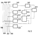
- the packet memory allocation 243 and the packet memory 246 are shown in FIG. 13.
- the packet memory allocation 243 consists of a stack read controller 2431, a packet stack 2432 and a stack write controller 2433. Data can be written into the packet memory 246 via a write address bus 2457 and a write data bus 2459 from the packet input units 241, and via a read address bus 2458 and a read data bus 24510 from the packet output units 242 can be read.
- the stack read controller 2431 recognizes the request for memory space on a packet display line 2455 and causes the packet stack 2432 to output a free memory address on a memory address bus 2453 for the packet input unit 241.
- the stack write controller 2433 recognizes the return of a free memory space on a return line 2456 and causes the packet stack 2432 to sort the address on a memory return bus 2454.
- the packet input unit 241 is shown in FIG. 11.
- the packet input unit 241 consists of an input part 2411, a packet filter 2412, a label exchange unit 2413, a data latch 2414, a control unit 2415, a port latch 2416, a memory address memory 2417, a counter 2418 and a decoding circuit 2419.
- the input part 2411 recognizes the incoming octets and reports this to the counter 2418.
- the packet filter 2412 recognizes an incoming packet (on the PV flag) and requests a free storage space from the memory allocation 243 via the packet display line 2455.
- the counter 2418 reports to the controller 2415 that it has received a complete label.
- the control unit 2415 then causes the label exchange unit to exchange the label cyclically and to write the label valid for this stage into the port latch 2416.
- the data is written into data latch 2414.
- Decoder circuit 2419 recognizes the bus cycle via packet input control bus 2451 and reports this to controller 2415. This causes data latch 2414 to put the data on write data bus 2459 and memory address memory 2417 to put the memory address on write address bus 2457.
- the control unit 2415 causes the port latch 2416 to put the address of the outgoing port on a port bus 24511.
- a packet exit unit 242 is shown in FIG.
- the packet output unit 242 consists of a packet output time slot controller 2421, a packet output decoding circuit 2426, a packet parts counter 2422, a packet counter 2423, write-in logic 2424, a packet queue 2425, a memory area address memory 2427, a memory area return memory 2428 and an output data latch: 24292 and reading the packets from the packet memory 246.
- the packet output decoding circuit 2426 recognizes its own address (ie the address of that output line, for which this packet output unit is responsible) on the port bus 24511.
- the packet output decoding circuit 2426 then causes the packet start address on the memory address bus 2457 to be read into the memory area address memory 2427.
- the write-in logic 2424 causes the packet start address to be written into the packet queue 2425.
- a packet has been read out output the start address of the freed memory area via the memory area return memory 2428 to the memory return bus 2454 and signals this on the return line 2456, timed by the packet output time slot controller 2421.
- the packets are read out in a time-controlled manner via the packet output time slot controller 2421.
- the packet output time slot controller 2421 clocks the packet part counter 2422.
- the overflow clocks the packet counter 2423.
- the packet part counter 2422 forms the read address with the start address from the packet queue 2425, which is given to the read address bus 2458.
- the packet data is read into the output data latch 2429 via the read data bus 24510.
Landscapes
- Engineering & Computer Science (AREA)
- Computer Networks & Wireless Communication (AREA)
- Signal Processing (AREA)
- Data Exchanges In Wide-Area Networks (AREA)
- Transmitters (AREA)
- Control Of Eletrric Generators (AREA)
Claims (9)
- Procédé de commutation d'informations d'un premier type et d'un second type, décomposées en paquets de longueur homogène, en particulier pour la commutation dans un réseau de connexion constitué de plusieurs étages, procédé dans lequel les informations du premier type sont décomposées en paquets, de façon telle qu'à chaque information du premier type, à l'intérieur d'une trame périodique, est mis à disposition au moins un créneau temporel propre, et dans lequel les informations du premier type sont commutées en technique synchrone de multiplexage par répartition dans le temps,
procédé caractérisé par le fait qu'avant la commutation, on décompose tous les paquets (CS1, CS2, PS1, PS2, PS3, LP, DP) en une pluralité de paquets partiels de longueur identique entre eux, que l'on déclasse-reclasse les paquets partiels selon un modèle prescrit et que l'on regroupe les paquets partiels d'autres paquets de façon telle que la trame est divisée en une pluralité de sous-trames, que le nombre des paquets partiels à l'intérieur d'une sous-trame est égal au nombre des paquets à l'intérieur d'une trame et qu'après la commutation on regroupe à nouveau les paquets partiels appartenant respectivement à un paquet. - Procédé selon la revendication 1, caractérisé par le fait que des paquets partiels qui appartiennent à une information du premier type (CS1, CS2) prennent, à l'intérieur de chacune des sous-trames, la même position que le paquet total dans la trame (figure 1).
- Procédé selon la revendication 2, caractérisé par le fait que l'on interclasse des paquets partiels, appartenant à une information du second type (PS1, PS2, PS3), dans leur succession d'origine, aux positions des sous-trames qui ne sont pas occupées par des paquets partiels appartenant à des informations du premier type (CS2, CS2) (figure 2).
- Procédé selon la revendication 3, caractérisé par le fait que des informations de commande (DP) et des intervalles de temps, dans la trame, qui ne présentent aucun contenu d'information (LP), sont traités comme des paquets qui appartiennent à une information du second type (PS1, PS2, PS3).
- Procédé selon l'une des revendications 1 à 4, caractérisé par le fait qu'à chaque étage du réseau de connexion, on convertit les paquets partiels appartenant à des informations du premier type en technique synchrone de multiplexage par répartition dans le temps, pour les faire passer, chacun, d'une position d'une sous-trame d'entrée en une position d'une sous-trame de sortie.
- Procédé selon la revendication 3 ou 4, caractérisé par le fait qu'à chaque étage du réseau de connexion, on convertit les paquets partiels appartenant à des informations du premier type en technique synchrone de multiplexage par répartition dans le temps, pour les faire passer, chacun, d'une position d'une sous-trame d'entrée en une position d'une sous-trame de sortie, et par le fait qu'à chaque étage du réseau de connexion on regroupe tout d'abord les paquets partiels appartenant à un paquet d'une information du second type pour en faire un paquet puis qu'on les interclasse, décomposés à nouveau en paquets partiels, dans les sous-trames de sortie successives, aux positions qui ne sont pas occupées par des paquets partiels appartenant à des informations du premier type.
- Dispositif de commutation présentant un réseau de connexion pour la commutation d'informations d'un premier type et d'un second type décomposées en paquets de longueur homogène, procédé dans lequel les informations du premier type sont décomposées en paquets, de façon telle qu'à chaque information du premier type, à l'intérieur d'une trame périodique, est mis à disposition au moins un créneau temporel propre, et dans lequel les informations du premier type sont commutées en technique synchrone de multiplexage par répartition dans le temps, en particulier, dispositif de commutation présentant un réseau de connexion constitué de plusieurs étages,
dispositif caractérisé par le fait qu'il comporte, sur chaque ligne (41) conduisant au réseau de connexion, un organe de tri d'entrée (10) et, sur chaque ligne (43) conduisant à une sortie, un organe de tri de sortie (15), que chaque organe de tri d'entrée (10) contient une mémoire d'entrée (15) et un organe de commande d'écriture et de lecture (17, 18) et que l'organe de commande d'écriture et de lecture (17, 18) est réalisé de façon à écrire tous les paquets (CS1, CS2, PS1, PS2, PS3, LP, DP) dans la mémoire d'entrée (15), puis à les y lire, de façon telle que les paquets y sont décomposés, selon un modèle prescrit, en une pluralité de paquets partiels de longueur identique entre eux et que les paquets partiels sont, périodiquement, déclassés-reclassés de façon telle que la trame s'y divise en une pluralité de sous-trames et que le nombre des paquets partiels à l'intérieur d'une sous-trame est égal au nombre des paquets à l'intérieur d'une trame, et que chaque organe de tri de sortie (30) contient une mémoire de sortie (34) et un organe de commande d'écriture et de lecture (37, 38) et que l'organe de commande d'écriture et de lecture (37, 38) est réalisé de façon à écrire dans la mémoire de sortie (34) et à y lire à nouveau de façon telle que, en inversant le modèle prescrit, les sous-trames s'y regroupent en trames et que les paquets partiels appartenant à un paquet s'y regroupent à nouveau. - Organe de tri d'entrée (10) pour un dispositif de commutation présentant un réseau de connexion pour la commutation d'informations d'un premier type et d'un second type décomposées en paquets de longueur homogène, procédé dans lequel les informations du premier type sont décomposées en paquets, de façon telle qu'à chaque information du premier type, à l'intérieur d'une trame périodique, est mis à disposition au moins un créneau temporel propre, et dans lequel les informations du premier type sont commutées en technique synchrone de multiplexage par répartition dans le temps, en particulier pour une ligne (41), conduisant au réseau de connexion, d'un dispositif de commutation présentant un réseau de connexion constitué de plusieurs étages, étant précisé que l'organe de tri d'entrée (10) contient une mémoire d'entrée (15) et un organe de commande d'écriture et de lecture (17, 18) qui est réalisée de façon à écrire tous les paquets (CS1, CS2, PS1, PS2, PS3, LP, DP) dans la mémoire d'entrée (15), puis à les y lire, de façon telle que les paquets y sont décomposés, selon un modèle prescrit, en une pluralité de paquets partiels de longueur identique entre eux et que les paquets partiels sont, périodiquement, déclassés- reclassés de façon telle que la trame s'y divise en une pluralité de sous-trames et que le nombre des paquets partiels à l'intérieur d'une sous-trame est égal au nombre de paquets à l'intérieur d'une trame.
- Organe de tri de sortie (30) pour un dispositif de commutation présentant un réseau de connexion pour la commutation d'informations d'un premier type et d'un second type décomposées en paquet de longueur homogène, procédé dans lequel les informations du premier type sont décomposées en paquets, de façon telle qu'à chaque information du premier type, à l'intérieur d'une trame périodique, est mis à disposition au moins un créneau temporel propre, et dans lequel les informations du premier type sont commutées en technique synchrone de multiplexage par répartition dans le temps, en particulier pour une ligne (43), conduisant à une sortie, d'un dispositif de commutation présentant un réseau de connexion constitué de plusieurs étages, étant précisé que, lors de la commutation, les paquets sont décomposés, selon un modèle prescrit, en une pluralité de paquets partiels de longueur identique entre eux et que les paquets partiels sont, périodiquement, déclassés-reclassés de façon telle que la trame s'y divise en une pluralité de sous-trames et que le nombre des paquets partiels à l'intérieur d'une sous-trame est égal au nombre des paquets à l'intérieur d'une trame, étant précisé que l'organe de tri de sortie (30) contient une mémoire de sortie (34) et un organe de commande d'écriture et de lecture (37, 38) qui est réalisé de façon à écrire dans la mémoire de sortie (34) et à y relire de façon telle qu'en inversant le modèle prescrit, les sous-trames s'y regroupent en trames et les paquets partiels appartenant à un paquet s'y regroupent à nouveau.
Priority Applications (1)
| Application Number | Priority Date | Filing Date | Title |
|---|---|---|---|
| AT88120438T ATE103129T1 (de) | 1987-12-18 | 1988-12-07 | Verfahren zur hybriden paketvermittlung und einrichtungen hierzu. |
Applications Claiming Priority (2)
| Application Number | Priority Date | Filing Date | Title |
|---|---|---|---|
| DE3742939 | 1987-12-18 | ||
| DE19873742939 DE3742939A1 (de) | 1987-12-18 | 1987-12-18 | Verfahren zur hybriden paketvermittlung und einrichtungen hierzu |
Publications (3)
| Publication Number | Publication Date |
|---|---|
| EP0320772A2 EP0320772A2 (fr) | 1989-06-21 |
| EP0320772A3 EP0320772A3 (fr) | 1991-07-31 |
| EP0320772B1 true EP0320772B1 (fr) | 1994-03-16 |
Family
ID=6342909
Family Applications (1)
| Application Number | Title | Priority Date | Filing Date |
|---|---|---|---|
| EP88120438A Expired - Lifetime EP0320772B1 (fr) | 1987-12-18 | 1988-12-07 | Procédé pour la commutation hybride de paquets et dispositifs à cet effet |
Country Status (12)
| Country | Link |
|---|---|
| US (1) | US4926416A (fr) |
| EP (1) | EP0320772B1 (fr) |
| JP (1) | JPH0728314B2 (fr) |
| KR (1) | KR960007670B1 (fr) |
| CN (1) | CN1010539B (fr) |
| AT (1) | ATE103129T1 (fr) |
| AU (1) | AU609231B2 (fr) |
| CA (1) | CA1330119C (fr) |
| DE (2) | DE3742939A1 (fr) |
| ES (1) | ES2052679T3 (fr) |
| MX (1) | MX174401B (fr) |
| NO (1) | NO173680C (fr) |
Families Citing this family (117)
| Publication number | Priority date | Publication date | Assignee | Title |
|---|---|---|---|---|
| DE3840688A1 (de) * | 1988-12-02 | 1990-06-13 | Standard Elektrik Lorenz Ag | Paketvermittlungsstelle und eingangs-umwandlungseinheit hierfuer |
| EP0401238B1 (fr) * | 1988-12-24 | 1993-06-30 | BELL TELEPHONE MANUFACTURING COMPANY Naamloze Vennootschap | Systeme de commutation de communications |
| JPH02228838A (ja) * | 1989-03-02 | 1990-09-11 | Oki Electric Ind Co Ltd | インターフェース回路 |
| FR2648646B1 (fr) * | 1989-06-19 | 1991-08-23 | Alcatel Business Systems | Procede et dispositif de gestion d'acces au support de transmission d'un reseau de commutation reparti multiservices |
| JP2907886B2 (ja) * | 1989-09-14 | 1999-06-21 | 株式会社日立製作所 | スイッチングシステム |
| JPH0824315B2 (ja) * | 1990-02-15 | 1996-03-06 | 富士通株式会社 | データ転送方式 |
| DE4008078A1 (de) * | 1990-03-14 | 1991-09-19 | Standard Elektrik Lorenz Ag | Kopierfaehige atm-vermittlungsstelle |
| JPH05505707A (ja) * | 1990-03-22 | 1993-08-19 | テルストラ コーポレイション リミティド | 遠隔通信回路網用の同時送信方法 |
| EP0462349B1 (fr) * | 1990-06-21 | 1995-02-22 | International Business Machines Corporation | Système de communication en anneau à large bande et méthode de commande d'accès |
| JP2878805B2 (ja) * | 1990-08-20 | 1999-04-05 | 株式会社東芝 | Atm交換機 |
| US5144619A (en) * | 1991-01-11 | 1992-09-01 | Northern Telecom Limited | Common memory switch for routing data signals comprising ATM and STM cells |
| DE4117869A1 (de) * | 1991-05-31 | 1992-12-03 | Standard Elektrik Lorenz Ag | Raum- und zeit-koppelelement |
| EP0522318A3 (en) * | 1991-06-26 | 1993-07-14 | Ant Nachrichtentechnik Gmbh | Switching modules for digital signals in asynchronous and synchronous transferring mode |
| SE468734B (sv) * | 1991-07-04 | 1993-03-08 | Ericsson Telefon Ab L M | Saett att i ramar packa kontinuerlig datainformation tillsammans med data i paketform och anvaendning av saett vid dataoeverfoering paa transmissionssystem |
| DE4127244A1 (de) * | 1991-08-17 | 1993-02-18 | Standard Elektrik Lorenz Ag | Hybrider koppelnetzbaustein |
| EP0528086B1 (fr) * | 1991-08-19 | 1999-08-04 | Siemens Aktiengesellschaft | Procédé et agencement pour la communication des informations STM à travers des commutateurs ATM |
| DE4130318A1 (de) * | 1991-09-12 | 1993-03-18 | Standard Elektrik Lorenz Ag | Verfahren und vorrichtung zur uebertragung von nachrichten in einem koppelnetzwerk |
| US5365521A (en) * | 1992-02-20 | 1994-11-15 | Nippon Telegraph And Telephone Corporation | Data transmission and transmission path setting among exchange modules in building block type exchanger |
| EP0645033B1 (fr) * | 1992-06-12 | 1996-12-04 | The Dow Chemical Company | Procede et systeme de communicaton intelligents destines a la commande de processus industriels |
| JPH06276214A (ja) * | 1993-03-18 | 1994-09-30 | Hitachi Ltd | Stm信号とatm信号の混在処理方法およびスイッチシステム |
| AU667004B2 (en) * | 1993-03-31 | 1996-02-29 | Nec Corporation | Cell processing system having first and second processing units capable of outputting first and second processed signals at the same time |
| GB9319449D0 (en) * | 1993-09-21 | 1993-11-03 | Plessey Telecomm | Telecommunications switching |
| US5390184A (en) * | 1993-09-30 | 1995-02-14 | Northern Telecom Limited | Flexible scheduling mechanism for ATM switches |
| EP0726002B1 (fr) * | 1993-10-26 | 1999-03-03 | Nortel Networks Corporation | Liaison de telecommunication numerique permettant le transport efficace de classes de paquets mixtes |
| US5682386A (en) | 1994-04-19 | 1997-10-28 | Multi-Tech Systems, Inc. | Data/voice/fax compression multiplexer |
| US5757801A (en) * | 1994-04-19 | 1998-05-26 | Multi-Tech Systems, Inc. | Advanced priority statistical multiplexer |
| US6031840A (en) * | 1995-12-07 | 2000-02-29 | Sprint Communications Co. L.P. | Telecommunications system |
| US6181703B1 (en) | 1995-09-08 | 2001-01-30 | Sprint Communications Company L. P. | System for managing telecommunications |
| US6314103B1 (en) | 1994-05-05 | 2001-11-06 | Sprint Communications Company, L.P. | System and method for allocating bandwidth for a call |
| PL177926B1 (pl) * | 1994-05-05 | 2000-01-31 | Sprint Communications Co | Sposób przetwarzania sygnałów sygnalizacji w systemie telekomunikacyjnym |
| US6023474A (en) * | 1996-11-22 | 2000-02-08 | Sprint Communications C.O.L.P. | Broadband telecommunications system interface |
| US5926482A (en) | 1994-05-05 | 1999-07-20 | Sprint Communications Co. L.P. | Telecommunications apparatus, system, and method with an enhanced signal transfer point |
| US6430195B1 (en) | 1994-05-05 | 2002-08-06 | Sprint Communications Company L.P. | Broadband telecommunications system interface |
| US5920562A (en) * | 1996-11-22 | 1999-07-06 | Sprint Communications Co. L.P. | Systems and methods for providing enhanced services for telecommunication call |
| US6631133B1 (en) | 1994-05-05 | 2003-10-07 | Sprint Communications Company L.P. | Broadband telecommunications system |
| US6633561B2 (en) | 1994-05-05 | 2003-10-14 | Sprint Communications Company, L.P. | Method, system and apparatus for telecommunications control |
| US6172977B1 (en) | 1994-05-05 | 2001-01-09 | Sprint Communications Company, L. P. | ATM direct access line system |
| US5991301A (en) | 1994-05-05 | 1999-11-23 | Sprint Communications Co. L.P. | Broadband telecommunications system |
| US5729544A (en) * | 1994-05-09 | 1998-03-17 | Motorola, Inc. | Method for transmitting data packets based on message type |
| US5570355A (en) * | 1994-11-17 | 1996-10-29 | Lucent Technologies Inc. | Method and apparatus enabling synchronous transfer mode and packet mode access for multiple services on a broadband communication network |
| US5590122A (en) * | 1994-12-22 | 1996-12-31 | Emc Corporation | Method and apparatus for reordering frames |
| GB9501116D0 (en) * | 1995-01-20 | 1995-03-08 | Plessey Telecomm | Asynchronous and plesiochronous transfer mode traffic |
| GB2337665B (en) * | 1995-03-31 | 2000-02-16 | Inmarsat Ltd | Communication method and apparatus |
| US5852718A (en) * | 1995-07-06 | 1998-12-22 | Sun Microsystems, Inc. | Method and apparatus for hybrid packet-switched and circuit-switched flow control in a computer system |
| US5862136A (en) * | 1995-07-07 | 1999-01-19 | Northern Telecom Limited | Telecommunications apparatus and method |
| US5841771A (en) * | 1995-07-07 | 1998-11-24 | Northern Telecom Limited | Telecommunications switch apparatus and method for time switching |
| GB9516777D0 (en) * | 1995-08-16 | 1995-10-18 | Int Computers Ltd | Network coupler |
| US5966163A (en) * | 1995-10-20 | 1999-10-12 | Scientific-Atlanta, Inc. | Providing constant bit rate upstream data transport in a two way cable system by scheduling preemptive grants for upstream data slots using selected fields of a plurality of grant fields |
| US7336649B1 (en) | 1995-12-20 | 2008-02-26 | Verizon Business Global Llc | Hybrid packet-switched and circuit-switched telephony system |
| WO1997028622A1 (fr) * | 1996-02-02 | 1997-08-07 | Sprint Communications Company, L.P. | Systeme de passerelle mta |
| US5826014A (en) * | 1996-02-06 | 1998-10-20 | Network Engineering Software | Firewall system for protecting network elements connected to a public network |
| US5898830A (en) * | 1996-10-17 | 1999-04-27 | Network Engineering Software | Firewall providing enhanced network security and user transparency |
| US5870550A (en) * | 1996-02-26 | 1999-02-09 | Network Engineering Software | Web server employing multi-homed, moldular framework |
| US8117298B1 (en) | 1996-02-26 | 2012-02-14 | Graphon Corporation | Multi-homed web server |
| GB2311440A (en) * | 1996-03-22 | 1997-09-24 | Northern Telecom Ltd | Communications network in which synchronous and asynchronous traffic is identified and separated at each node |
| US5940393A (en) * | 1996-05-28 | 1999-08-17 | Sprint Communications Co. L.P. | Telecommunications system with a connection processing system |
| DE69634295T2 (de) * | 1996-06-19 | 2005-06-09 | Freescale Semiconductors, Inc., Austin | ATM-Zellenverarbeitungssystem und Methode zum Zugriff auf einen Verbindungsspeicher |
| JPH10178451A (ja) * | 1996-10-17 | 1998-06-30 | Fujitsu Ltd | ハイブリッド交換機、交換機、及びこれらの交換機におけるstmデータ再配置方法 |
| US5933414A (en) * | 1996-10-29 | 1999-08-03 | International Business Machines Corporation | Method to control jitter in high-speed packet-switched networks |
| WO1998023079A1 (fr) * | 1996-11-22 | 1998-05-28 | Sprint Communications Company, L.P. | Systeme et procede de transport d'un appel dans un reseau de telecommunication |
| US6002689A (en) | 1996-11-22 | 1999-12-14 | Sprint Communications Co. L.P. | System and method for interfacing a local communication device |
| US6014378A (en) * | 1996-11-22 | 2000-01-11 | Sprint Communications Company, L.P. | Telecommunications tandem system for circuit-based traffic |
| US6115380A (en) * | 1996-11-22 | 2000-09-05 | Sprint Communications Co., L.P. | Broadband telecommunications system |
| US6493347B2 (en) | 1996-12-16 | 2002-12-10 | Juniper Networks, Inc. | Memory organization in a switching device |
| US6067299A (en) * | 1997-04-16 | 2000-05-23 | Sprint Communications Company, L.P. | Communications system for providing ATM connections and echo cancellation |
| US6137800A (en) * | 1997-05-09 | 2000-10-24 | Sprint Communications Company, L. P. | System and method for connecting a call |
| US6704327B1 (en) | 1997-05-09 | 2004-03-09 | Sprint Communications Company, L.P. | System and method for connecting a call |
| US6178170B1 (en) | 1997-05-13 | 2001-01-23 | Sprint Communications Company, L. P. | System and method for transporting a call |
| US6141690A (en) * | 1997-07-31 | 2000-10-31 | Hewlett-Packard Company | Computer network address mapping |
| US6256308B1 (en) | 1998-01-20 | 2001-07-03 | Telefonaktiebolaget Lm Ericsson | Multi-service circuit for telecommunications |
| US6483837B1 (en) | 1998-02-20 | 2002-11-19 | Sprint Communications Company L.P. | System and method for connecting a call with an interworking system |
| US6563918B1 (en) | 1998-02-20 | 2003-05-13 | Sprint Communications Company, LP | Telecommunications system architecture for connecting a call |
| US6167041A (en) * | 1998-03-17 | 2000-12-26 | Afanador; J. Abraham | Switch with flexible link list manager for handling ATM and STM traffic |
| US6546022B1 (en) | 1998-04-03 | 2003-04-08 | Sprint Communications Company, L.P. | Method, system and apparatus for processing information in a telecommunications system |
| US6160871A (en) | 1998-04-10 | 2000-12-12 | Sprint Communications Company, L.P. | Communications test system |
| US6404735B1 (en) | 1998-04-30 | 2002-06-11 | Nortel Networks Limited | Methods and apparatus for distributed control of a multi-class network |
| US6667956B2 (en) | 1998-05-01 | 2003-12-23 | Nortel Networks Limited | Multi-class network |
| US6028867A (en) * | 1998-06-15 | 2000-02-22 | Covad Communications Group, Inc. | System, method, and network for providing high speed remote access from any location connected by a local loop to a central office |
| US6580721B1 (en) * | 1998-08-11 | 2003-06-17 | Nortel Networks Limited | Routing and rate control in a universal transfer mode network |
| US6535519B1 (en) * | 1998-08-28 | 2003-03-18 | Lsi Logic Corporation | Method and apparatus for data sharing between two different blocks in an integrated circuit |
| US6628652B1 (en) * | 1998-09-18 | 2003-09-30 | Lucent Technologies Inc. | Flexible telecommunications switching network |
| US6181693B1 (en) | 1998-10-08 | 2001-01-30 | High Speed Video, L.L.C. | High speed video transmission over telephone lines |
| US6614781B1 (en) * | 1998-11-20 | 2003-09-02 | Level 3 Communications, Inc. | Voice over data telecommunications network architecture |
| US6442169B1 (en) | 1998-11-20 | 2002-08-27 | Level 3 Communications, Inc. | System and method for bypassing data from egress facilities |
| US6888833B1 (en) | 1998-12-22 | 2005-05-03 | Sprint Communications Company L.P. | System and method for processing call signaling |
| US6785282B1 (en) | 1998-12-22 | 2004-08-31 | Sprint Communications Company L.P. | System and method for connecting a call with a gateway system |
| US6724765B1 (en) | 1998-12-22 | 2004-04-20 | Sprint Communications Company, L.P. | Telecommunication call processing and connection system architecture |
| US6982950B1 (en) | 1998-12-22 | 2006-01-03 | Sprint Communications Company L.P. | System and method for connecting a call in a tandem architecture |
| US6496512B1 (en) * | 1998-12-22 | 2002-12-17 | Sprint Communications Company L.P. | System and method for connecting calls with a time division multiplex matrix |
| US6853647B1 (en) | 1999-02-17 | 2005-02-08 | Covad Communications Group, Inc. | System method and network for providing high speed remote access from any location connected by a local loop to a central office |
| US6891836B1 (en) | 1999-06-03 | 2005-05-10 | Fujitsu Network Communications, Inc. | Switching complex architecture and operation |
| US6317426B1 (en) * | 1999-06-03 | 2001-11-13 | Fujitsu Network Communications, Inc. | Method and apparatus for hybrid protection in a switching network |
| US6498792B1 (en) | 1999-06-03 | 2002-12-24 | Fujitsu Network Communications, Inc. | Method and apparatus for switching signals of multiple different communication protocols |
| US6674751B1 (en) * | 1999-06-03 | 2004-01-06 | Fujitsu Network Communications, Inc. | Serialized bus communication and control architecture |
| US6396847B1 (en) | 1999-06-03 | 2002-05-28 | Fujitsu Networks Communications, Inc. | Dialable data services/TDM bandwidth management |
| US6501758B1 (en) * | 1999-06-03 | 2002-12-31 | Fujitsu Network Communications, Inc. | Hybrid ATM/TDM transport over a common fiber ring |
| US8254394B1 (en) | 1999-06-29 | 2012-08-28 | Cisco Technology, Inc. | Technique for providing constant bit rate (CBR) service over a time-slotted access channel |
| US6650660B1 (en) * | 1999-07-27 | 2003-11-18 | Pluris, Inc. | Apparatus and method for synchronization of multiple data paths and recovery from lost synchronization |
| US6473397B1 (en) | 1999-08-10 | 2002-10-29 | Nortel Networks Limited | Add/drop multiplexer and method, and Bi-directional line switcher ring featuring such multiplexers |
| US6816497B1 (en) | 1999-11-05 | 2004-11-09 | Sprint Communications Company, L.P. | System and method for processing a call |
| US6704314B1 (en) | 1999-12-15 | 2004-03-09 | Sprint Communications Company, L.P. | Method and apparatus to control cell substitution |
| JP3522619B2 (ja) * | 2000-01-05 | 2004-04-26 | 株式会社エヌ・ティ・ティ・ドコモ | マルチキャリアcdma伝送システムにおける送信機 |
| US7324635B2 (en) | 2000-05-04 | 2008-01-29 | Telemaze Llc | Branch calling and caller ID based call routing telephone features |
| US8396052B1 (en) * | 2000-07-20 | 2013-03-12 | Alcatel Lucent | Apparatus and method for synchronous and asynchronous switching of internet protocol traffic |
| KR100425253B1 (ko) * | 2001-04-18 | 2004-03-30 | 주식회사 현대시스콤 | 무선통신 시스템에서의 순방향 패킷 송수신 방법 |
| KR100431702B1 (ko) * | 2001-12-27 | 2004-05-17 | 엘지전자 주식회사 | 셀 기반 이더넷 스위치 시스템 |
| US7310333B1 (en) * | 2002-06-28 | 2007-12-18 | Ciena Corporation | Switching control mechanism for supporting reconfiguaration without invoking a rearrangement algorithm |
| EP1521496A1 (fr) * | 2003-09-30 | 2005-04-06 | Alcatel | Commutateur universel, procédé pour la réalisation d'une tâche de commutation, unité d'entrée, unité de sortie et unité de raccordement |
| EP1521497A3 (fr) * | 2003-09-30 | 2006-05-31 | Alcatel | Commutateur universel, procédé pour la réalisation d'une tâche de commutation, unité d'entrée, unité de sortie et unité de raccordement |
| KR101085644B1 (ko) * | 2004-11-18 | 2011-11-22 | 삼성전자주식회사 | 동기화 이더넷을 위한 시스템 및 시스템 계층 구성 방법 |
| US8681749B2 (en) | 2007-01-04 | 2014-03-25 | Qualcomm Incorporated | Control resource mapping for a wireless communication system |
| US8433357B2 (en) * | 2007-01-04 | 2013-04-30 | Qualcomm Incorporated | Method and apparatus for utilizing other sector interference (OSI) indication |
| US8457315B2 (en) * | 2007-01-05 | 2013-06-04 | Qualcomm Incorporated | Pilot transmission in a wireless communication system |
| US8320407B2 (en) * | 2007-01-05 | 2012-11-27 | Qualcomm Incorporated | Mapping of subpackets to resources in a communication system |
| CN101837528A (zh) * | 2010-02-21 | 2010-09-22 | 王辉 | 切丝机 |
| WO2012056335A1 (fr) * | 2010-10-28 | 2012-05-03 | International Business Machines Corporation | Procédé et système de transmission de paquets de données dans un réseau |
| CN102359185A (zh) * | 2011-08-08 | 2012-02-22 | 中国舰船研究设计中心 | 一种大型钢结构构件与混凝土构件的连接结构及施工方法 |
Family Cites Families (14)
| Publication number | Priority date | Publication date | Assignee | Title |
|---|---|---|---|---|
| US4569041A (en) * | 1983-03-17 | 1986-02-04 | Nec Corporation | Integrated circuit/packet switching system |
| GB2139852B (en) * | 1983-05-13 | 1986-05-29 | Standard Telephones Cables Ltd | Data network |
| US4592048A (en) * | 1984-05-03 | 1986-05-27 | At&T Bell Laboratories | Integrated packet switching and circuit switching system |
| GB2162022B (en) * | 1984-07-17 | 1988-03-02 | Stc Plc | Data transmission system |
| JPS61187497A (ja) * | 1985-02-15 | 1986-08-21 | Nec Corp | 回線/パケツト統合交換方式 |
| FR2589656B1 (fr) * | 1985-07-03 | 1987-12-11 | Servel Michel | Procede et dispositif de conversion de multitrame de canaux numeriques en multitrame de paquets |
| JPS6218155A (ja) * | 1985-07-17 | 1987-01-27 | Nec Corp | 回線/パケツト統合交換方式 |
| EP0214352B1 (fr) * | 1985-08-13 | 1990-10-24 | International Business Machines Corporation | Méthode et système de transport adaptatif pour la commutation circuit/paquet |
| US4698802A (en) * | 1986-03-07 | 1987-10-06 | American Telephone And Telegraph Company And At&T Information Systems Inc. | Combined circuit and packet switching system |
| US4679190A (en) * | 1986-04-28 | 1987-07-07 | International Business Machines Corporation | Distributed voice-data switching on multi-stage interconnection networks |
| US4731785A (en) * | 1986-06-20 | 1988-03-15 | American Telephone And Telegraph Company | Combined circuit switch and packet switching system |
| DE3685217D1 (de) * | 1986-08-27 | 1992-06-11 | Ibm | Vorrichtung zur optimierten bandbreitenzuordnung zwischen durchschaltevermittelten zeitschlitzen und paket-bitstrom in einem kommunikationsnetz. |
| US4785446A (en) * | 1986-11-07 | 1988-11-15 | International Business Machines Corporation | Distributed bit switching of a multistage interconnection network |
| DE3742941A1 (de) * | 1987-12-18 | 1989-07-06 | Standard Elektrik Lorenz Ag | Einrichtungen zur paketvermittlung |
-
1987
- 1987-12-18 DE DE19873742939 patent/DE3742939A1/de not_active Withdrawn
-
1988
- 1988-12-07 ES ES88120438T patent/ES2052679T3/es not_active Expired - Lifetime
- 1988-12-07 DE DE88120438T patent/DE3888480D1/de not_active Expired - Fee Related
- 1988-12-07 AT AT88120438T patent/ATE103129T1/de not_active IP Right Cessation
- 1988-12-07 EP EP88120438A patent/EP0320772B1/fr not_active Expired - Lifetime
- 1988-12-09 AU AU26685/88A patent/AU609231B2/en not_active Ceased
- 1988-12-14 MX MX014172A patent/MX174401B/es unknown
- 1988-12-14 NO NO885542A patent/NO173680C/no unknown
- 1988-12-16 US US07/286,306 patent/US4926416A/en not_active Expired - Lifetime
- 1988-12-16 JP JP63318300A patent/JPH0728314B2/ja not_active Expired - Lifetime
- 1988-12-16 CA CA000586149A patent/CA1330119C/fr not_active Expired - Fee Related
- 1988-12-17 KR KR1019880016869A patent/KR960007670B1/ko not_active IP Right Cessation
- 1988-12-17 CN CN88108701A patent/CN1010539B/zh not_active Expired
Also Published As
| Publication number | Publication date |
|---|---|
| CN1035927A (zh) | 1989-09-27 |
| ATE103129T1 (de) | 1994-04-15 |
| NO173680B (no) | 1993-10-04 |
| JPH024054A (ja) | 1990-01-09 |
| CN1010539B (zh) | 1990-11-21 |
| AU2668588A (en) | 1989-06-22 |
| JPH0728314B2 (ja) | 1995-03-29 |
| NO173680C (no) | 1994-01-12 |
| ES2052679T3 (es) | 1994-07-16 |
| DE3742939A1 (de) | 1989-07-06 |
| EP0320772A3 (fr) | 1991-07-31 |
| US4926416A (en) | 1990-05-15 |
| CA1330119C (fr) | 1994-06-07 |
| KR960007670B1 (ko) | 1996-06-08 |
| NO885542L (no) | 1989-06-19 |
| MX174401B (es) | 1994-05-13 |
| DE3888480D1 (de) | 1994-04-21 |
| KR890011462A (ko) | 1989-08-14 |
| AU609231B2 (en) | 1991-04-26 |
| EP0320772A2 (fr) | 1989-06-21 |
| NO885542D0 (no) | 1988-12-14 |
Similar Documents
| Publication | Publication Date | Title |
|---|---|---|
| EP0320772B1 (fr) | Procédé pour la commutation hybride de paquets et dispositifs à cet effet | |
| EP0320714B1 (fr) | Dispositifs pour la commutation à paquets | |
| EP0446589B1 (fr) | Commutateur ATM avec capacité de duplication | |
| DE3752370T2 (de) | Vermittlungssystem | |
| EP0435046B1 (fr) | Méthode pour le rétablissement de la séquence des cellules originelles, notamment pour un commutateur ATM, ainsi qu'unité de sortie pour celui-ci | |
| EP0412343B1 (fr) | Réseau de commutation et module pour un système ATM | |
| DE69737361T2 (de) | Schnelle vermittlungsvorrichtung | |
| DE60031596T2 (de) | Zeitmultiplex-Vermittlungssystem (TDM) mit sehr breitem Speicher | |
| DE60317890T2 (de) | Verfahren und anordnung zur lokalen synchronisation in verteilten master-slave-kommunikationssystemen | |
| DE69637462T2 (de) | ATM-Vermittlungsstelle mit Eingangs- und Ausgangsanschlussstellen | |
| DE3214189C2 (fr) | ||
| DE2136361A1 (de) | Verfahren zur Zeitmultiplex-Nachrichtenübertragung und Vermittlungseinrichtung für eine Anlage zur Durchführung dieses Verfahrens | |
| EP0186141A2 (fr) | Multiplexeur démultiplexeur avec répartiteur de canaux pour signaux numériques de différents niveaux de hiérarchie | |
| EP0156339A2 (fr) | Méthode et dispositif pour la réalisation et l'opération d'une liaison multiplex temporelle à large bande dans un central de commutation à division dans le temps | |
| EP0428089B1 (fr) | Noeud d'abonné d'un système de transmission de données numérique | |
| DE60124869T2 (de) | Vermittlungssystem und verfahren mit niedrigerer und deterministischen verzögerung | |
| EP0322075B1 (fr) | Réseau de commutation et dispositif de commande pour un système de commutation | |
| EP0066653B1 (fr) | Circuit pour centraux de télécommunication à multiplexage temporel, en particulier pour centraux téléphoniques MIC dont les voies temporelles sont utilisées partiellement pour la transmission de données et partiellement pour la transmission d'informations de signalisation | |
| EP0173274B1 (fr) | Méthode et montage pour la réalisation et la maintenance d'une liaison à division temporelle à large bande | |
| EP0443672B1 (fr) | Système à mode de transfert asynchrone | |
| EP0528206A2 (fr) | Module de commutation hybride | |
| EP0321050B1 (fr) | Noeud de commutation d'un système de commutation à large bande | |
| EP0960551B1 (fr) | Procede et circuit pour transmettre des cellules de donnees dans le cadre de liaisons virtuelles presentant differentes priorites | |
| DE69635238T2 (de) | Multiplex und Zuweisungsgerät für ATM-Netzwerk | |
| DE3816747A1 (de) | Leistungsvermittelnde paket-vermittlungseinrichtung |
Legal Events
| Date | Code | Title | Description |
|---|---|---|---|
| PUAI | Public reference made under article 153(3) epc to a published international application that has entered the european phase |
Free format text: ORIGINAL CODE: 0009012 |
|
| AK | Designated contracting states |
Kind code of ref document: A2 Designated state(s): AT BE CH DE ES FR GB GR IT LI NL SE |
|
| PUAL | Search report despatched |
Free format text: ORIGINAL CODE: 0009013 |
|
| AK | Designated contracting states |
Kind code of ref document: A3 Designated state(s): AT BE CH DE ES FR GB GR IT LI NL SE |
|
| 17P | Request for examination filed |
Effective date: 19910719 |
|
| 17Q | First examination report despatched |
Effective date: 19920806 |
|
| RAP3 | Party data changed (applicant data changed or rights of an application transferred) |
Owner name: ALCATEL SEL AKTIENGESELLSCHAFT |
|
| RBV | Designated contracting states (corrected) |
Designated state(s): AT BE CH DE ES FR GB IT LI NL SE |
|
| GRAA | (expected) grant |
Free format text: ORIGINAL CODE: 0009210 |
|
| AK | Designated contracting states |
Kind code of ref document: B1 Designated state(s): AT BE CH DE ES FR GB IT LI NL SE |
|
| REF | Corresponds to: |
Ref document number: 103129 Country of ref document: AT Date of ref document: 19940415 Kind code of ref document: T |
|
| ITF | It: translation for a ep patent filed |
Owner name: DOTT. ANTONIO SERGI |
|
| REF | Corresponds to: |
Ref document number: 3888480 Country of ref document: DE Date of ref document: 19940421 |
|
| GBT | Gb: translation of ep patent filed (gb section 77(6)(a)/1977) |
Effective date: 19940329 |
|
| ET | Fr: translation filed | ||
| REG | Reference to a national code |
Ref country code: ES Ref legal event code: FG2A Ref document number: 2052679 Country of ref document: ES Kind code of ref document: T3 |
|
| PLBE | No opposition filed within time limit |
Free format text: ORIGINAL CODE: 0009261 |
|
| STAA | Information on the status of an ep patent application or granted ep patent |
Free format text: STATUS: NO OPPOSITION FILED WITHIN TIME LIMIT |
|
| EAL | Se: european patent in force in sweden |
Ref document number: 88120438.2 |
|
| 26N | No opposition filed | ||
| PGFP | Annual fee paid to national office [announced via postgrant information from national office to epo] |
Ref country code: GB Payment date: 20011116 Year of fee payment: 14 |
|
| PGFP | Annual fee paid to national office [announced via postgrant information from national office to epo] |
Ref country code: NL Payment date: 20011120 Year of fee payment: 14 Ref country code: CH Payment date: 20011120 Year of fee payment: 14 |
|
| PGFP | Annual fee paid to national office [announced via postgrant information from national office to epo] |
Ref country code: SE Payment date: 20011203 Year of fee payment: 14 Ref country code: AT Payment date: 20011203 Year of fee payment: 14 |
|
| PGFP | Annual fee paid to national office [announced via postgrant information from national office to epo] |
Ref country code: DE Payment date: 20011208 Year of fee payment: 14 |
|
| PGFP | Annual fee paid to national office [announced via postgrant information from national office to epo] |
Ref country code: FR Payment date: 20011211 Year of fee payment: 14 |
|
| PGFP | Annual fee paid to national office [announced via postgrant information from national office to epo] |
Ref country code: ES Payment date: 20011212 Year of fee payment: 14 |
|
| PGFP | Annual fee paid to national office [announced via postgrant information from national office to epo] |
Ref country code: BE Payment date: 20011220 Year of fee payment: 14 |
|
| REG | Reference to a national code |
Ref country code: GB Ref legal event code: IF02 |
|
| PG25 | Lapsed in a contracting state [announced via postgrant information from national office to epo] |
Ref country code: GB Free format text: LAPSE BECAUSE OF NON-PAYMENT OF DUE FEES Effective date: 20021207 Ref country code: AT Free format text: LAPSE BECAUSE OF NON-PAYMENT OF DUE FEES Effective date: 20021207 |
|
| PG25 | Lapsed in a contracting state [announced via postgrant information from national office to epo] |
Ref country code: SE Free format text: LAPSE BECAUSE OF NON-PAYMENT OF DUE FEES Effective date: 20021208 |
|
| PG25 | Lapsed in a contracting state [announced via postgrant information from national office to epo] |
Ref country code: ES Free format text: LAPSE BECAUSE OF NON-PAYMENT OF DUE FEES Effective date: 20021209 |
|
| PG25 | Lapsed in a contracting state [announced via postgrant information from national office to epo] |
Ref country code: LI Free format text: LAPSE BECAUSE OF NON-PAYMENT OF DUE FEES Effective date: 20021231 Ref country code: CH Free format text: LAPSE BECAUSE OF NON-PAYMENT OF DUE FEES Effective date: 20021231 Ref country code: BE Free format text: LAPSE BECAUSE OF NON-PAYMENT OF DUE FEES Effective date: 20021231 |
|
| BERE | Be: lapsed |
Owner name: *ALCATEL SEL A.G. Effective date: 20021231 |
|
| PG25 | Lapsed in a contracting state [announced via postgrant information from national office to epo] |
Ref country code: NL Free format text: LAPSE BECAUSE OF NON-PAYMENT OF DUE FEES Effective date: 20030701 Ref country code: DE Free format text: LAPSE BECAUSE OF NON-PAYMENT OF DUE FEES Effective date: 20030701 |
|
| EUG | Se: european patent has lapsed | ||
| GBPC | Gb: european patent ceased through non-payment of renewal fee | ||
| REG | Reference to a national code |
Ref country code: CH Ref legal event code: PL |
|
| NLV4 | Nl: lapsed or anulled due to non-payment of the annual fee |
Effective date: 20030701 |
|
| PG25 | Lapsed in a contracting state [announced via postgrant information from national office to epo] |
Ref country code: FR Free format text: LAPSE BECAUSE OF NON-PAYMENT OF DUE FEES Effective date: 20030901 |
|
| REG | Reference to a national code |
Ref country code: FR Ref legal event code: ST |
|
| REG | Reference to a national code |
Ref country code: ES Ref legal event code: FD2A Effective date: 20021209 |
|
| PG25 | Lapsed in a contracting state [announced via postgrant information from national office to epo] |
Ref country code: IT Free format text: LAPSE BECAUSE OF NON-PAYMENT OF DUE FEES Effective date: 20051207 |