EP0320643B2 - Réservoir de carburant - Google Patents
Réservoir de carburant Download PDFInfo
- Publication number
- EP0320643B2 EP0320643B2 EP88119256A EP88119256A EP0320643B2 EP 0320643 B2 EP0320643 B2 EP 0320643B2 EP 88119256 A EP88119256 A EP 88119256A EP 88119256 A EP88119256 A EP 88119256A EP 0320643 B2 EP0320643 B2 EP 0320643B2
- Authority
- EP
- European Patent Office
- Prior art keywords
- housing
- filling
- control valve
- front wall
- wall opening
- Prior art date
- Legal status (The legal status is an assumption and is not a legal conclusion. Google has not performed a legal analysis and makes no representation as to the accuracy of the status listed.)
- Expired - Lifetime
Links
- 239000002828 fuel tank Substances 0.000 title claims description 21
- OKTJSMMVPCPJKN-UHFFFAOYSA-N Carbon Chemical compound [C] OKTJSMMVPCPJKN-UHFFFAOYSA-N 0.000 claims description 28
- 239000000446 fuel Substances 0.000 claims description 25
- 238000003780 insertion Methods 0.000 claims description 4
- 230000037431 insertion Effects 0.000 claims description 4
- 229910052799 carbon Inorganic materials 0.000 claims 2
- 238000009795 derivation Methods 0.000 claims 1
- 239000003517 fume Substances 0.000 claims 1
- 239000000945 filler Substances 0.000 description 37
- 238000010276 construction Methods 0.000 description 5
- 238000007789 sealing Methods 0.000 description 5
- 238000009423 ventilation Methods 0.000 description 4
- 230000009471 action Effects 0.000 description 3
- 238000000034 method Methods 0.000 description 2
- 230000008569 process Effects 0.000 description 2
- 230000008901 benefit Effects 0.000 description 1
- 238000002485 combustion reaction Methods 0.000 description 1
- 230000006835 compression Effects 0.000 description 1
- 238000007906 compression Methods 0.000 description 1
- 229920001971 elastomer Polymers 0.000 description 1
- 239000000806 elastomer Substances 0.000 description 1
- 231100001261 hazardous Toxicity 0.000 description 1
- 230000036541 health Effects 0.000 description 1
- 229930195733 hydrocarbon Natural products 0.000 description 1
- 150000002430 hydrocarbons Chemical class 0.000 description 1
- 230000001771 impaired effect Effects 0.000 description 1
- 238000009434 installation Methods 0.000 description 1
- 230000007246 mechanism Effects 0.000 description 1
- 230000000284 resting effect Effects 0.000 description 1
Images
Classifications
-
- B—PERFORMING OPERATIONS; TRANSPORTING
- B60—VEHICLES IN GENERAL
- B60K—ARRANGEMENT OR MOUNTING OF PROPULSION UNITS OR OF TRANSMISSIONS IN VEHICLES; ARRANGEMENT OR MOUNTING OF PLURAL DIVERSE PRIME-MOVERS IN VEHICLES; AUXILIARY DRIVES FOR VEHICLES; INSTRUMENTATION OR DASHBOARDS FOR VEHICLES; ARRANGEMENTS IN CONNECTION WITH COOLING, AIR INTAKE, GAS EXHAUST OR FUEL SUPPLY OF PROPULSION UNITS IN VEHICLES
- B60K15/00—Arrangement in connection with fuel supply of combustion engines or other fuel consuming energy converters, e.g. fuel cells; Mounting or construction of fuel tanks
- B60K15/03—Fuel tanks
- B60K15/04—Tank inlets
-
- B—PERFORMING OPERATIONS; TRANSPORTING
- B60—VEHICLES IN GENERAL
- B60K—ARRANGEMENT OR MOUNTING OF PROPULSION UNITS OR OF TRANSMISSIONS IN VEHICLES; ARRANGEMENT OR MOUNTING OF PLURAL DIVERSE PRIME-MOVERS IN VEHICLES; AUXILIARY DRIVES FOR VEHICLES; INSTRUMENTATION OR DASHBOARDS FOR VEHICLES; ARRANGEMENTS IN CONNECTION WITH COOLING, AIR INTAKE, GAS EXHAUST OR FUEL SUPPLY OF PROPULSION UNITS IN VEHICLES
- B60K15/00—Arrangement in connection with fuel supply of combustion engines or other fuel consuming energy converters, e.g. fuel cells; Mounting or construction of fuel tanks
- B60K15/03—Fuel tanks
- B60K15/035—Fuel tanks characterised by venting means
- B60K15/03519—Valve arrangements in the vent line
-
- B—PERFORMING OPERATIONS; TRANSPORTING
- B60—VEHICLES IN GENERAL
- B60K—ARRANGEMENT OR MOUNTING OF PROPULSION UNITS OR OF TRANSMISSIONS IN VEHICLES; ARRANGEMENT OR MOUNTING OF PLURAL DIVERSE PRIME-MOVERS IN VEHICLES; AUXILIARY DRIVES FOR VEHICLES; INSTRUMENTATION OR DASHBOARDS FOR VEHICLES; ARRANGEMENTS IN CONNECTION WITH COOLING, AIR INTAKE, GAS EXHAUST OR FUEL SUPPLY OF PROPULSION UNITS IN VEHICLES
- B60K15/00—Arrangement in connection with fuel supply of combustion engines or other fuel consuming energy converters, e.g. fuel cells; Mounting or construction of fuel tanks
- B60K15/03—Fuel tanks
- B60K15/04—Tank inlets
- B60K2015/0458—Details of the tank inlet
- B60K2015/048—Arrangements for sealing the fuel inlet during filling
-
- Y—GENERAL TAGGING OF NEW TECHNOLOGICAL DEVELOPMENTS; GENERAL TAGGING OF CROSS-SECTIONAL TECHNOLOGIES SPANNING OVER SEVERAL SECTIONS OF THE IPC; TECHNICAL SUBJECTS COVERED BY FORMER USPC CROSS-REFERENCE ART COLLECTIONS [XRACs] AND DIGESTS
- Y10—TECHNICAL SUBJECTS COVERED BY FORMER USPC
- Y10T—TECHNICAL SUBJECTS COVERED BY FORMER US CLASSIFICATION
- Y10T137/00—Fluid handling
- Y10T137/8593—Systems
- Y10T137/86292—System with plural openings, one a gas vent or access opening
- Y10T137/86324—Tank with gas vent and inlet or outlet
- Y10T137/86332—Vent and inlet or outlet in unitary mounting
Definitions
- the invention relates to a fuel tank with a safety device arranged in its filler neck for collecting fuel vapors when refueling with the features of the preamble of the claim.
- a fuel tank with such a safety device is known (DE-OS 36 05 708).
- the control valve of this safety device ensures that there is no connection between the activated carbon filter and the fuel tank when the filler neck is closed, thus in the latter with a suitable design of a ventilation device for the operation of the internal combustion engine of the motor vehicle concerned, a desired excess pressure is maintained and it is also ensured that at Accidental inclined or upside-down position of the fuel tank means that no fuel can escape into the open via the activated carbon filter.
- the control valve of this safety gear When refueling, the control valve of this safety gear must be brought into its open position so that the fuel vapors, which consist of hydrocarbons and are therefore extremely hazardous to health, cannot flow out of the fuel tank into the atmosphere but can flow out into the activated carbon filter.
- the filling pipe of the nozzle which is to be inserted into the filler supports, serves indirectly.
- a narrowing guide channel is provided for the filler pipe within the filler neck, sealingly receiving the fuel nozzle filler pipe, the inner end of which is drawn from the filler neck by means of a self-closing flap withdrawn nozzle is kept gastight.
- the control valve forms a structural unit for itself, the valve member of which can be moved mechanically into the open position by the closure flap to be pivoted into its open position by means of the filling nozzle.
- the closure flap is equipped with a fork-shaped actuating lever, the fork legs of which, when the closure flap is pivoted into its open position, lie against a head of a valve member of the control valve and thereby move the valve member against its action against a restoring force into its passage position which connects the fuel tank to the activated carbon filter .
- This allows fuel vapors to escape during the refueling process without escaping from the filler neck.
- control valve a valve mechanism with a specially designed valve member, which is to be actuated by the closure flap which also has to be specially designed, and two lines to be laid outside the filler neck and to be connected to the control valve or filler neck, one of which leads away from the fuel tank and the other is to be connected to the activated carbon filter.
- the object of the present invention is to simplify both the construction and installation of the control valve and the means required for its actuation and to design such that only one line to be installed outside the filler neck, namely the line connecting the control valve to the activated carbon filter, is provided is.
- a special valve member is thus omitted, in that the closure flap also takes on its task.
- An opening to be closed by the closure flap forms the valve seat of the control valve which is located within the filler neck, so that the filler neck at the same time receives the function of a line for connecting the container space which receives fuel vapors to the control valve.
- the closure flap of the control valve and the guide channel form components which are combined in a housing to form a structural unit, which structural unit can advantageously be installed in the closable end piece of the filler neck.
- the opening to be closed by the closure flap of the guide channel narrowing the filler neck and receiving the nozzle filler pipe also forms the valve seat of the control valve.
- the arrangement of the pressure relief valve connected to the intermediate space and the activated carbon filter creates the prerequisite for pressure compensation to be brought about only from a certain overpressure.
- the closing force of the pressure relief valve can be selected so that the locking force generated by the overpressure acting on the closure flap cannot hinder the insertion of the nozzle filler pipe, and in the case of a disproportionately large increase in pressure in the fuel tank caused by fire, for example, the overpressure caused by the Usually designed as a pressure relief valve filler cap can be kept uncritical.
- the pressure relief valve offers a further advantage in that, for example, no fuel can leak when cornering, should it have been forgotten to properly close the filler neck after refueling. It also ensures that when the filler neck is opened, neither fuel can evaporate nor spill out of the port opening.
- DE-PS 36 02 844 already discloses a closure device for a fuel tank filler neck, through which displaced fuel vapors are discharged during the refueling process.
- This closure device likewise has a self-closing control valve, the valve member of which is formed by a closure flap which can be pivoted into its open position against the action of a closing force by a nozzle filler pipe introduced into the filler neck.
- control valve only serves to supply the fuel vapors flowing out of the filler neck in its open position to an annular channel of an orifice ring overlapping the filler neck, in which they are deflected and distributed over the entire circumference of the orifice ring to the atmosphere in such a way that the person filling the fuel tank is not bothered or endangered by the vapors.
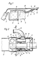
- FIG. 10 denotes a fuel tank, the filler neck 12 of which is equipped with a catch device 16 for capturing vapors from fuel during refueling within its neck end piece 12 'which can be closed by means of a closure cap 14 (FIG. 2).
- a ventilation device which is known per se and is installed in the fuel tank 10, from which a ventilation pipe 22 which, for example, emerges from the tank bottom 20 and leads to an activated carbon filter 21 leads away and is also equipped with a tank ventilation valve 24.
- the catching device 16 is located in the filler neck end 12 'above the maximum container fill level 26. It forms a structural unit which is inserted as a whole in a sealed manner into the filler neck end piece 12' and is connected to the activated carbon filter 21 via a connecting line 28 connected to the latter.
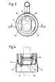
- the catching device 16 has a cylindrical housing 30, the housing jacket 32 of which carries two sealing rings 34 and 36 on the outer circumference at a spacing from one another, which sealingly bear against the inner circumference of the filler neck end pieces 12 '. Between the two sealing rings 34 and 36 there is an opening 38 of the housing jacket 32, which leads to a connection opening 40 of the connecting line 28 on the connecting piece.
- the opening 38 of the housing shell 32 opens radially into a valve chamber 42 of a control valve 43 located inside the housing 30, which is accessible from the inside of the socket only via an end wall opening 46 provided in a housing end wall 44 facing the fuel tank 10.
- a guide channel 48 which extends parallel to the housing axis and into which the filling pipe 50 of a fuel nozzle 52 can be inserted for refueling.
- the guide channel 48 opens in the insertion direction of the filling tube 50 into a funnel 54 tapering in this direction, the smallest diameter forms a further end wall opening 56.
- 58 denotes a sealing ring arranged in the guide channel 48 which, when the nozzle filling pipe 50 is inserted, surrounds it in a sealing manner on the outer circumference and thus ensures that fuel vapors present in the filler neck 12 cannot escape into the atmosphere via the guide channel 48.
- Both end wall openings 46 and 56 are assigned a common closure flap 60, which is hinged to the housing end wall 44 at 61 and against the action of a return spring (not shown), for example a torsion spring, through the nozzle filler tube 50 when it is inserted into the guide channel 48 and the end wall opening 56 in its open or open position (Fig. 2) is pivotable.
- a return spring for example a torsion spring
- the closure flap 60 forms the valve member which can be controlled in a closed and open position.
- the closure flap 60 is in this case still provided with a contact surface resting on the edge of the end wall opening 46, e.g. disc-shaped elastomer seal 62.
- the housing end wall 44 also contains a further end wall opening 64, through which, when the nozzle fill pipe 50 is removed from the filler neck 12, a space 66 (FIG. 2) is present between the funnel 54 and the guide channel 48 Bypass from the fuel tank 10 to the closure cap 14, which is preferably equipped with a safety valve, is created.
- the closure flap 60 With the closure flap 60 closed, the same pressure as in the remaining part of the filler neck 12 or in the fuel tank 10 also prevails in the region of the guide channel 48 up to the closure lid 14, so that the closure flap 60 can be opened easily.
- the top position of the Krattstoff matterers 10 it is ensured that no fuel can flow through the activated carbon filter 21 via the control valve 43.
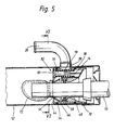
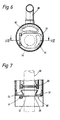
- FIGS. 5 to 7 differs from the construction described above in that instead of the end wall opening 64 forming the bypass, an end wall opening 70 forming part of a control valve 68 and closable by a closure flap 72 is provided, which via the interspace 66 with the to the activated carbon filter 21 leading connection line 28 is connected.
- a housing space 74 connected to the connecting line 28 is provided, in which a valve member 76 is slidably arranged, which constantly tries to hold a compression spring 78 in its closed position, which keeps an end wall opening 80 closed, and which together with this forms a safety valve 82.
- This embodiment of the catching device likewise prevents fuel from leaking through the activated carbon filter 21 when the flap 72 is in the top position of the fuel tank 10. Furthermore, even when the filler neck 12 is left open, no fuel will leak from it and neither will fuel spill out when the filler neck 12 is opened.
- This design also prevents fuel vapors from escaping when the nozzle is opened.
- the safety valve 82 opens when a certain overpressure in the fuel tank is reached, so that the tank internal pressure can be kept uncritical.
Landscapes
- Engineering & Computer Science (AREA)
- Life Sciences & Earth Sciences (AREA)
- Sustainable Development (AREA)
- Sustainable Energy (AREA)
- Chemical & Material Sciences (AREA)
- Combustion & Propulsion (AREA)
- Transportation (AREA)
- Mechanical Engineering (AREA)
- Cooling, Air Intake And Gas Exhaust, And Fuel Tank Arrangements In Propulsion Units (AREA)
- Details Of Rigid Or Semi-Rigid Containers (AREA)
Claims (1)
caractérisé
par la combinaison des caractéristiques suivantes :
Applications Claiming Priority (2)
| Application Number | Priority Date | Filing Date | Title |
|---|---|---|---|
| DE3742258A DE3742258C2 (de) | 1987-12-12 | 1987-12-12 | Kraftstoffbehälter |
| DE3742258 | 1987-12-12 |
Publications (4)
| Publication Number | Publication Date |
|---|---|
| EP0320643A2 EP0320643A2 (fr) | 1989-06-21 |
| EP0320643A3 EP0320643A3 (en) | 1990-09-05 |
| EP0320643B1 EP0320643B1 (fr) | 1992-06-17 |
| EP0320643B2 true EP0320643B2 (fr) | 1994-09-21 |
Family
ID=6342520
Family Applications (1)
| Application Number | Title | Priority Date | Filing Date |
|---|---|---|---|
| EP88119256A Expired - Lifetime EP0320643B2 (fr) | 1987-12-12 | 1988-11-19 | Réservoir de carburant |
Country Status (4)
| Country | Link |
|---|---|
| US (1) | US5040575A (fr) |
| EP (1) | EP0320643B2 (fr) |
| JP (1) | JPH0647338B2 (fr) |
| DE (1) | DE3742258C2 (fr) |
Families Citing this family (19)
| Publication number | Priority date | Publication date | Assignee | Title |
|---|---|---|---|---|
| JPH0810947Y2 (ja) * | 1990-03-22 | 1996-03-29 | 日本電気株式会社 | 電気二重層コンデンサ |
| DE4034467A1 (de) * | 1990-10-30 | 1992-05-07 | Freudenberg Carl Fa | Dichtungsanordnung zur verwendung im einfuellstutzen eines kraftstofftanks |
| US5322100A (en) * | 1993-01-27 | 1994-06-21 | Borg-Warner Automotive, Inc. | Fuel filler module |
| US5320147A (en) * | 1993-05-06 | 1994-06-14 | Ford Motor Company | Fuel filler pipe fill control module |
| US5439129A (en) * | 1994-07-06 | 1995-08-08 | Borg-Warner Automotive, Inc. | Fuel tank filler pipe arrangement |
| FR2725942B1 (fr) * | 1994-10-21 | 1996-11-29 | Renault | Dispositif de limitation de l'evaporation du carburant contenu dans un reservoir |
| DE19547177B4 (de) * | 1994-12-24 | 2008-03-13 | Volkswagen Ag | Kraftstoffbehälter, der mit einem weiteren Behälter verbunden ist und Verfahren zu dessen Herstellung |
| US5878795A (en) * | 1995-04-10 | 1999-03-09 | Armellino; Gary | Fuel spill collector device |
| AT402624B (de) * | 1995-10-10 | 1997-07-25 | Blau Automobiltechnik Gmbh | Endstück für einen fahrzeugtank-einfüllstutzen endstück für einen fahrzeugtank-einfüllstutzen |
| DE19714813C1 (de) * | 1997-04-10 | 1998-07-23 | Freudenberg Carl Fa | Kraftstoffbehälter |
| US6029719A (en) * | 1998-04-13 | 2000-02-29 | Firma Carl Freudenberg | Fuel tank |
| US6302133B1 (en) * | 1999-11-15 | 2001-10-16 | Honda Giken Kogyo Kabushiki Kaisha | Fuel tank |
| DE20209335U1 (de) * | 2002-06-14 | 2002-08-29 | Gerdes GmbH, 50170 Kerpen | Stutzenabschluss mit Labyrinthdichtung |
| JP4268865B2 (ja) * | 2003-12-26 | 2009-05-27 | 株式会社マーレ フィルターシステムズ | 燃料捕捉装置 |
| JP4769600B2 (ja) * | 2006-03-09 | 2011-09-07 | 本田技研工業株式会社 | 給油口装置 |
| JP4894701B2 (ja) * | 2007-09-28 | 2012-03-14 | 豊田合成株式会社 | フィラーネック |
| US10029560B2 (en) * | 2015-03-19 | 2018-07-24 | Toyoda Gosei Co., Ltd. | Fuel supply apparatus |
| JP6500726B2 (ja) * | 2015-09-28 | 2019-04-17 | 豊田合成株式会社 | 燃料供給装置 |
| DE102018118272A1 (de) * | 2018-07-27 | 2020-01-30 | Kautex Textron Gmbh & Co. Kg | Einfüllstutzen für druckloses Betankungsabschalten und Nachtanken und Betriebsflüssigkeitsbehälter mit Einfüllstutzen |
Family Cites Families (9)
| Publication number | Priority date | Publication date | Assignee | Title |
|---|---|---|---|---|
| US4142647A (en) * | 1977-12-15 | 1979-03-06 | General Motors Corporation | Fuel tank venting system |
| JPS61127025U (fr) * | 1985-01-29 | 1986-08-09 | ||
| JPH039466Y2 (fr) * | 1985-02-23 | 1991-03-08 | ||
| US4595452A (en) * | 1985-03-11 | 1986-06-17 | Oerlikon-Buhrle U.S.A. Inc. | Method and apparatus for plasma etching |
| DE3602844C1 (de) * | 1986-01-30 | 1987-01-02 | Temtec Fahrzeugtechnik Entwicklungsgesellschaft Mbh | Blendenring |
| US4724861A (en) * | 1986-08-18 | 1988-02-16 | General Motors Corporation | Fuel tank venting |
| US4874020A (en) * | 1987-03-26 | 1989-10-17 | Whitehead Engineered Products, Inc. | System for controlling the release of fuel vapors from a vehicle fuel tank |
| US4809863A (en) * | 1987-10-16 | 1989-03-07 | Colt Industries Inc | Fill neck assembly for on board refueling vapor recovery system |
| DE3742256C1 (de) * | 1987-12-12 | 1989-03-02 | Daimler Benz Ag | Vorrichtung zum Auffangen von Kraftstoffdaempfen beim Betanken eines Kraftstoffbehaelters |
-
1987
- 1987-12-12 DE DE3742258A patent/DE3742258C2/de not_active Expired - Fee Related
-
1988
- 1988-11-19 EP EP88119256A patent/EP0320643B2/fr not_active Expired - Lifetime
- 1988-12-09 JP JP63310224A patent/JPH0647338B2/ja not_active Expired - Lifetime
-
1990
- 1990-01-23 US US07/469,020 patent/US5040575A/en not_active Expired - Lifetime
Also Published As
| Publication number | Publication date |
|---|---|
| US5040575A (en) | 1991-08-20 |
| JPH023531A (ja) | 1990-01-09 |
| DE3742258C2 (de) | 1993-12-02 |
| EP0320643A3 (en) | 1990-09-05 |
| JPH0647338B2 (ja) | 1994-06-22 |
| EP0320643A2 (fr) | 1989-06-21 |
| EP0320643B1 (fr) | 1992-06-17 |
| DE3742258C1 (de) | 1989-03-02 |
Similar Documents
| Publication | Publication Date | Title |
|---|---|---|
| EP0320643B2 (fr) | Réservoir de carburant | |
| DE3742256C1 (de) | Vorrichtung zum Auffangen von Kraftstoffdaempfen beim Betanken eines Kraftstoffbehaelters | |
| EP0233183B1 (fr) | Dispositif pour limiter le remplissage de recipients et pour l'introduction et l'extraction de l'air de ceux-ci, et surtout des reservoirs d'essence des vehicules a moteur | |
| DE19637399C2 (de) | Dampfsteuervorrichtung für einen Fahrzeugkrafstofftank | |
| DE3605708C2 (fr) | ||
| DE4012368C2 (fr) | ||
| DE19605922B4 (de) | Entlüftungseinrichtung für Fahrzeug-Kraftstofftanks | |
| DE4109337A1 (de) | Verschlusskappenlose fahrzeug-auftankvorrichtung | |
| DE3527773C2 (fr) | ||
| EP0804348B1 (fr) | Dispositif de fermeture du tuyau de remplissage du reservoir d'essence d'un vehicule | |
| DE19911489B4 (de) | Vorrichtung zum Steuern von Fluidströmen beim Betanken | |
| DE19802078B4 (de) | Kraftfahrzeugtank | |
| AT407386B (de) | Vorrichtung zum steuern der gasströme und flüssigkeitsniveaus in einem orvr-betankungssystem | |
| DE4242599C2 (de) | Behälterverschluß | |
| DE19540267B4 (de) | Tankentlüftung | |
| DE3803670C1 (fr) | ||
| DE4102961A1 (de) | Tankanordnung fuer ein kraftfahrzeug | |
| EP1049598B1 (fr) | Dispositif permettant d'eviter de remplir de maniere excessive un reservoir de carburant | |
| DE3704641A1 (de) | Vorrichtung zum auffangen von kraftstoffdaempfen beim fuellen eines kraftstofftanks | |
| DE19642308A1 (de) | Kraftfahrzeugtank mit Betriebsentlüftung | |
| DE3742259C1 (de) | Kraftstoffbehaelter | |
| DE10139619A1 (de) | Verfahren und Vorrichtung zum emissionsarmen Betankungsbetrieb einer Tankanlage insbesondere eines Kraftfahrzeuges | |
| AT402624B (de) | Endstück für einen fahrzeugtank-einfüllstutzen endstück für einen fahrzeugtank-einfüllstutzen | |
| EP0915771B1 (fr) | Dispositif permettant d'empecher le trop-plein d'un reservoir d'essence | |
| EP1154909A1 (fr) | Soupape et reservoir d'essence de vehicule dote d'une soupape |
Legal Events
| Date | Code | Title | Description |
|---|---|---|---|
| PUAI | Public reference made under article 153(3) epc to a published international application that has entered the european phase |
Free format text: ORIGINAL CODE: 0009012 |
|
| AK | Designated contracting states |
Kind code of ref document: A2 Designated state(s): FR GB IT SE |
|
| PUAL | Search report despatched |
Free format text: ORIGINAL CODE: 0009013 |
|
| RHK1 | Main classification (correction) |
Ipc: B60K 15/01 |
|
| AK | Designated contracting states |
Kind code of ref document: A3 Designated state(s): FR GB IT SE |
|
| 17P | Request for examination filed |
Effective date: 19910304 |
|
| 17Q | First examination report despatched |
Effective date: 19911125 |
|
| GRAA | (expected) grant |
Free format text: ORIGINAL CODE: 0009210 |
|
| AK | Designated contracting states |
Kind code of ref document: B1 Designated state(s): FR GB IT SE |
|
| ITF | It: translation for a ep patent filed | ||
| GBT | Gb: translation of ep patent filed (gb section 77(6)(a)/1977) | ||
| ET | Fr: translation filed | ||
| PLBI | Opposition filed |
Free format text: ORIGINAL CODE: 0009260 |
|
| 26 | Opposition filed |
Opponent name: BAYERISCHE MOTOREN WERKE AG, PATENTABTEILUNG AJ-3, Effective date: 19930310 |
|
| PUAA | Information related to the publication of a b2 document modified |
Free format text: ORIGINAL CODE: 0009299PMAP |
|
| PUAH | Patent maintained in amended form |
Free format text: ORIGINAL CODE: 0009272 |
|
| STAA | Information on the status of an ep patent application or granted ep patent |
Free format text: STATUS: PATENT MAINTAINED AS AMENDED |
|
| 27A | Patent maintained in amended form |
Effective date: 19940921 |
|
| AK | Designated contracting states |
Kind code of ref document: B2 Designated state(s): SE |
|
| R27A | Patent maintained in amended form (corrected) |
Effective date: 19940921 |
|
| ITF | It: translation for a ep patent filed | ||
| ET3 | Fr: translation filed ** decision concerning opposition | ||
| EAL | Se: european patent in force in sweden |
Ref document number: 88119256.1 |
|
| GBTA | Gb: translation of amended ep patent filed (gb section 77(6)(b)/1977) |
Effective date: 19950110 |
|
| REG | Reference to a national code |
Ref country code: GB Ref legal event code: 732E |
|
| REG | Reference to a national code |
Ref country code: GB Ref legal event code: IF02 |
|
| PGFP | Annual fee paid to national office [announced via postgrant information from national office to epo] |
Ref country code: SE Payment date: 20021028 Year of fee payment: 15 |
|
| PGFP | Annual fee paid to national office [announced via postgrant information from national office to epo] |
Ref country code: GB Payment date: 20021030 Year of fee payment: 15 |
|
| PGFP | Annual fee paid to national office [announced via postgrant information from national office to epo] |
Ref country code: FR Payment date: 20021104 Year of fee payment: 15 |
|
| PG25 | Lapsed in a contracting state [announced via postgrant information from national office to epo] |
Ref country code: GB Free format text: LAPSE BECAUSE OF NON-PAYMENT OF DUE FEES Effective date: 20031119 |
|
| PG25 | Lapsed in a contracting state [announced via postgrant information from national office to epo] |
Ref country code: SE Free format text: LAPSE BECAUSE OF NON-PAYMENT OF DUE FEES Effective date: 20031120 |
|
| EUG | Se: european patent has lapsed | ||
| GBPC | Gb: european patent ceased through non-payment of renewal fee |
Effective date: 20031119 |
|
| PG25 | Lapsed in a contracting state [announced via postgrant information from national office to epo] |
Ref country code: FR Free format text: LAPSE BECAUSE OF NON-PAYMENT OF DUE FEES Effective date: 20040730 |
|
| REG | Reference to a national code |
Ref country code: FR Ref legal event code: ST |
|
| PG25 | Lapsed in a contracting state [announced via postgrant information from national office to epo] |
Ref country code: IT Free format text: LAPSE BECAUSE OF NON-PAYMENT OF DUE FEES;WARNING: LAPSES OF ITALIAN PATENTS WITH EFFECTIVE DATE BEFORE 2007 MAY HAVE OCCURRED AT ANY TIME BEFORE 2007. THE CORRECT EFFECTIVE DATE MAY BE DIFFERENT FROM THE ONE RECORDED. Effective date: 20051119 |