EP0804348B1 - Dispositif de fermeture du tuyau de remplissage du reservoir d'essence d'un vehicule - Google Patents
Dispositif de fermeture du tuyau de remplissage du reservoir d'essence d'un vehicule Download PDFInfo
- Publication number
- EP0804348B1 EP0804348B1 EP96938844A EP96938844A EP0804348B1 EP 0804348 B1 EP0804348 B1 EP 0804348B1 EP 96938844 A EP96938844 A EP 96938844A EP 96938844 A EP96938844 A EP 96938844A EP 0804348 B1 EP0804348 B1 EP 0804348B1
- Authority
- EP
- European Patent Office
- Prior art keywords
- flap
- line
- filler neck
- valve
- closure device
- Prior art date
- Legal status (The legal status is an assumption and is not a legal conclusion. Google has not performed a legal analysis and makes no representation as to the accuracy of the status listed.)
- Expired - Lifetime
Links
- 239000000945 filler Substances 0.000 title claims abstract description 25
- 239000000446 fuel Substances 0.000 claims abstract description 18
- 239000002828 fuel tank Substances 0.000 claims description 4
- 238000011084 recovery Methods 0.000 abstract description 5
- 210000003739 neck Anatomy 0.000 description 18
- OKTJSMMVPCPJKN-UHFFFAOYSA-N Carbon Chemical compound [C] OKTJSMMVPCPJKN-UHFFFAOYSA-N 0.000 description 8
- 239000007789 gas Substances 0.000 description 6
- 239000012530 fluid Substances 0.000 description 4
- 238000000034 method Methods 0.000 description 4
- 238000010276 construction Methods 0.000 description 3
- 238000002485 combustion reaction Methods 0.000 description 2
- 238000010521 absorption reaction Methods 0.000 description 1
- 238000005429 filling process Methods 0.000 description 1
- 238000011010 flushing procedure Methods 0.000 description 1
- 230000005484 gravity Effects 0.000 description 1
- 239000010763 heavy fuel oil Substances 0.000 description 1
- 238000007789 sealing Methods 0.000 description 1
- 239000000725 suspension Substances 0.000 description 1
- 238000009423 ventilation Methods 0.000 description 1
Images

Classifications
-
- B—PERFORMING OPERATIONS; TRANSPORTING
- B60—VEHICLES IN GENERAL
- B60K—ARRANGEMENT OR MOUNTING OF PROPULSION UNITS OR OF TRANSMISSIONS IN VEHICLES; ARRANGEMENT OR MOUNTING OF PLURAL DIVERSE PRIME-MOVERS IN VEHICLES; AUXILIARY DRIVES FOR VEHICLES; INSTRUMENTATION OR DASHBOARDS FOR VEHICLES; ARRANGEMENTS IN CONNECTION WITH COOLING, AIR INTAKE, GAS EXHAUST OR FUEL SUPPLY OF PROPULSION UNITS IN VEHICLES
- B60K15/00—Arrangement in connection with fuel supply of combustion engines or other fuel consuming energy converters, e.g. fuel cells; Mounting or construction of fuel tanks
- B60K15/03—Fuel tanks
- B60K15/035—Fuel tanks characterised by venting means
- B60K15/03519—Valve arrangements in the vent line
-
- B—PERFORMING OPERATIONS; TRANSPORTING
- B60—VEHICLES IN GENERAL
- B60K—ARRANGEMENT OR MOUNTING OF PROPULSION UNITS OR OF TRANSMISSIONS IN VEHICLES; ARRANGEMENT OR MOUNTING OF PLURAL DIVERSE PRIME-MOVERS IN VEHICLES; AUXILIARY DRIVES FOR VEHICLES; INSTRUMENTATION OR DASHBOARDS FOR VEHICLES; ARRANGEMENTS IN CONNECTION WITH COOLING, AIR INTAKE, GAS EXHAUST OR FUEL SUPPLY OF PROPULSION UNITS IN VEHICLES
- B60K15/00—Arrangement in connection with fuel supply of combustion engines or other fuel consuming energy converters, e.g. fuel cells; Mounting or construction of fuel tanks
- B60K15/03—Fuel tanks
- B60K15/04—Tank inlets
- B60K2015/0458—Details of the tank inlet
- B60K2015/048—Arrangements for sealing the fuel inlet during filling
Definitions
- the present invention relates to a closure device according to the preamble of claim 1.
- a closure device is known from DE-A-43 43 498.
- a Vacuum or pressure relief valve required to the vehicle tank to equalize pressure for ventilation.
- ORVR systems Onboard Refueling Vapor Recovery Systems
- the collecting container is in the Flushing driving operation of the combustion supply gases, which remove the fuel residue from the activated carbon filter and incinerate it. Additional valves are therefore required which appropriate suction or Collection openings and corresponding pressure equalization openings during driving release.
- the invention aims to provide a closure device of the type mentioned in the introduction so that they all necessary for the functioning of a vehicle tank Contains fluid circuit elements.
- This goal is achieved according to the invention achieved in that the multi-way valve in another Position the filler neck below the flap with a further, larger collecting line leading to the collecting container Flow cross-section connects that the flap with Can be loaded in the closing direction with the help of a pressure device, and that the actuator the multi-way valve in the Load position of the flap in said one position controls, however, in the relief position of the flap in the other position mentioned tax.
- the closure device combines the Functions of a filler neck closure, an ORVR valve and a pressure compensation valve, which together with the Release or closing the flap can be controlled, which itself due to the pressure device as a denser Neck closure serves.
- the multi-way valve in the above one position with the filler neck below the flap one starting from a gas collection space of the vehicle tank Overfill line connects. This also functions as a Overfill valves integrated.
- the multi-way valve is a combined Rotary and face slide valve is, the said additional collecting line on the circumference, on the other hand the pressure compensation line, the said a collecting line and if necessary the overfill pipe in the front plate of the rotary and face slide open socket towards the filler neck.
- This construction takes into account the space requirements of the Control opening of the large-diameter first collecting line, which derive the fuel vapors generated during refueling got to.
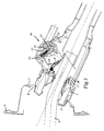
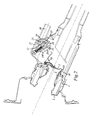
- 1 to 3 is the upper end of a filler neck 1, the lower end (not shown) of a vehicle fuel tank.
- a filler neck 1 In the upper end of the filler neck 1 an approximately pot-shaped insert 2 is inserted tightly, which reduced an opening 3 at its lower end Diameter for the passage of the filling tube 4 one Has nozzle (not shown).
- the opening 3 can be closed with the aid of a flap 5 hinged on one side, which by a spring 6 against the underside Edge of the opening is biased.
- the upper end of the filler neck 1 together with the insert 2 passes through with the interposition of a sealing collar 7 Opening 8 in a recessed area of a vehicle body 9.
- the reset area can be identified by an appropriate Body flap (not shown) are covered.
- a pressure finger 10 articulated which with Using an actuator 11 against the bottom of the Flap 5 can be acted upon (see Fig. 3).
- the pressure finger 10 is a two-armed lever in the example shown, and the Actuating device 11 comprises a pivotable, on its End provided with a spring-loaded pressure roller 12 Cam 13, which on the one lever arm of the pressure finger 10th presses and its other lever arm against the bottom of the Flap 5 presses (Fig. 3).
- the pressure finger shown and actuator construction is any other Form of pressing device for the flap 5 possible.
- the cam 13 is pivoted via a shaft 14 which can be obtained from a suitable e.g. electrical, hydraulic or pneumatic (not shown) servo motor driven becomes. Manual operation is also possible.
- the flap 5 For a possible after pulling off the filling pipe 4 above the flap 5 remaining fuel excess in the Letting the tank drain out protrudes into the movement path 15 of the Flap 5 in the area before its closed position has a locking projection 16.
- the locking projection 16 is by a radially inward directed grooves in a spring tongue 17 formed on the edge the opening 3 is clamped in the axial direction.
- the locking device combines all for the construction of one ORVR system required fluid circuit elements and still some more necessary in connection with vehicle tanks Elements, as explained in more detail below.
- the drive shaft 14 of the actuator 11 is in the example shown the control shaft of a 5/2-way valve 19, which contains a combined rotary and face slide 19 '.
- the rotary and face slide 19 ' has a control plate 20, which are arranged centrally around the shaft 14 Control holes 21 to 23 is provided, which with connection holes 24 to 26 in a fixed, on the control plate 20th brought into alignment (not shown) end plate can be.
- the face plate is part of a rotary and slide valve 19 'in stock, towards the filler neck interior open socket 27, which in the wall of the filler neck 1 is formed.
- connection holes 24 to 26 and the connection opening 30 are with respect to the connection holes 24 to 26 and the connection opening 30 arranged so that in the relief position shown in FIGS. 1 and 2 Flap 5, the connection holes 24 to 26 closed and the Connection opening 30 is connected to the inside of the filler neck, whereas in the loading position shown in FIG Flap 5, the connection holes 24 to 26 with the filler neck inside are connected and the connection opening 30 is closed is.
- connection opening 30 is a collecting line for fuel vapors connected, which to a fuel vapor receiver (not shown) leads with an activated carbon filter to the absorption of Is equipped with fuel vapors.
- the collecting container is during operation of the vehicle from combustion supply gases which flushes the fuel residues from the Detach the activated carbon filter and incinerate it.
- the Components and the functionality of this system are the Known specialist.
- the connection opening 30 and the subsequent The collecting line has a sufficiently large flow cross-section, around the amount of fuel vapor generated during refueling (Fig. 1) to be able to dissipate.
- connection hole is 24 with a second one leading to the collecting container Collection line of smaller flow cross-section connected.
- a rollover valve is switched on in the second collecting line. The rollover valve closes under gravity at one Rollover and prevents fuel from escaping via the fuel vapor collecting line and the collecting container.
- connection bores 25 and 26 serve for the Connect one from the top of the vehicle tank Pressure equalization line and one from a gas collection room overflow line outgoing from the top of the vehicle tank.
- the pressure compensation line (connection bore 25) is in driving mode (Fig. 3) over the filler neck interior and the second Collection line connected to the fuel vapor collection container.
- the function of the overfill line (connection bore 26) is known to the expert; it is closed during the refueling process and allows an air supply to be built up in the gas collection space of the vehicle tank. After the refueling process the air supply is vented into the upper end of the filler neck, so that fuel runs into the tank in the filler neck.
- valve functions described can be not only with the help of the shown turning and Slide valve achieve, rather any, multi-way valve known in the art can be used.
- the Invention is also suitable for applications in which an overfill line is dispensed with, in which case a corresponding one reduced multi-way valve is used.
- the connection holes for the pressure compensation line (25) and the second collecting line (24) could also be used directly while driving, i.e. without intermediate connection via the filler neck inside, be connected to each other.
Landscapes
- Engineering & Computer Science (AREA)
- Life Sciences & Earth Sciences (AREA)
- Sustainable Development (AREA)
- Sustainable Energy (AREA)
- Chemical & Material Sciences (AREA)
- Combustion & Propulsion (AREA)
- Transportation (AREA)
- Mechanical Engineering (AREA)
- Cooling, Air Intake And Gas Exhaust, And Fuel Tank Arrangements In Propulsion Units (AREA)
- Nozzles (AREA)
Claims (4)
- Dispositif de fermeture pour une tubulure (1) de remplissage d'un réservoir d'automobile, qui comporte une ouverture (3) pourvue d'un clapet (5) permettant le passage du tube de remplissage (4) d'un pistolet de remplissage, le clapet (5) étant précontraint par un ressort (6) contre le bord inférieur de l'ouverture (3), et comportant une soupape à plusieurs voies (19) qui, dans une position, relie une canalisation de compensation de pression (25) raccordée au réservoir du véhicule, à une canalisation de collecte(24) qui est reliée au récipient de collecte de la vapeur de carburant et est équipée d'une soupape à retournement, caractérisé en ce que dans une autre position, la soupape à plusieurs voies (19) relie la tubulure de remplissage (1) au-dessus du clapet (5) à une autre canalisation de collecte (30) qui aboutit au récipient de collecte et possède une section transversale d'écoulement plus étendue, que le clapet (5) peut être en outre chargé dans le sens de la fermeture à l'aide d'un dispositif de serrage (10,11), et que, lorsque le clapet (5) est dans la position de charge, le dispositif de serrage (10,11) place la soupape à plusieurs voies (19) dans ladite une position, alors que lorsque le clapet (5) est dans la position de détente, le dispositif de serrage place la soupape à voies multiples dans l'autre position indiquée.
- Dispositif de fermeture selon la revendication 1, caractérisé en ce que dans ladite une position, la soupape à voies multiples (19) relie la tubulure de remplissage (1) au-dessous du clapet (5) à une canalisation de trop-plein (26) qui sort d'un espace de collecte de gaz du réservoir du véhicule.
- Dispositif de fermeture selon la revendication 1 ou 2, caractérisé en ce que la soupape à plusieurs voies (19) est une soupape combiné à tiroir rotatif et plat, ladite autre canalisation de collecte (30) débouchant au niveau de la périphérie, tandis que la canalisation (25), ladite une canalisation de collecte (24) et éventuellement la canalisation de trop-plein (26) débouchent dans la plaque frontale d'un manchon (27) qui supporte le tiroir rotatif et plat (19') de la soupape et qui est ouvert en direction de la tubulure de remplissage (1).
- Dispositif de fermeture selon la revendication 3, dans lequel le dispositif de serrage (11) comporte une came (13), qui attaque un doigt de serrage, caractérisé en ce que la came (13) est fixée sur l'arbre d'actionnement (14) du tiroir rotatif et plat (19').
Applications Claiming Priority (4)
| Application Number | Priority Date | Filing Date | Title |
|---|---|---|---|
| AT1894/95 | 1995-11-21 | ||
| AT0189495A AT403142B (de) | 1995-11-21 | 1995-11-21 | Verschlussvorrichtung für einen fahrzeugtank-einfüllstutzen |
| AT189495 | 1995-11-21 | ||
| PCT/AT1996/000231 WO1997018966A1 (fr) | 1995-11-21 | 1996-11-21 | Dispositif de fermeture du tuyau de remplissage du reservoir d'essence d'un vehicule |
Publications (2)
| Publication Number | Publication Date |
|---|---|
| EP0804348A1 EP0804348A1 (fr) | 1997-11-05 |
| EP0804348B1 true EP0804348B1 (fr) | 2000-02-23 |
Family
ID=3523319
Family Applications (1)
| Application Number | Title | Priority Date | Filing Date |
|---|---|---|---|
| EP96938844A Expired - Lifetime EP0804348B1 (fr) | 1995-11-21 | 1996-11-21 | Dispositif de fermeture du tuyau de remplissage du reservoir d'essence d'un vehicule |
Country Status (5)
| Country | Link |
|---|---|
| US (1) | US5921424A (fr) |
| EP (1) | EP0804348B1 (fr) |
| AT (2) | AT403142B (fr) |
| DE (1) | DE59604493D1 (fr) |
| WO (1) | WO1997018966A1 (fr) |
Families Citing this family (18)
| Publication number | Priority date | Publication date | Assignee | Title |
|---|---|---|---|---|
| AT406850B (de) * | 1998-10-12 | 2000-09-25 | Tesma Motoren Getriebetechnik | Antriebsvorrichtung für eine verschlusseinrichtung eines fahrzeugtank-einfüllstutzens |
| DE19934422B4 (de) * | 1999-07-22 | 2006-06-01 | Audi Ag | Einfüllstutzen |
| DE19956349B4 (de) * | 1999-11-24 | 2005-03-31 | Blau Kunststofftechnik Zweigniederlassung Der Tesma Europa Gmbh | Tankverschluß |
| AT4281U1 (de) * | 2000-03-31 | 2001-05-25 | Tesma Motoren Getriebetechnik | Einfüllstutzen |
| DE10326587A1 (de) * | 2003-06-13 | 2005-01-05 | Gresens, Dieter, Rojales | Vorrichtung und Verfahren zur Sicherung eines Tankinhalts |
| DE10331073B4 (de) * | 2003-07-09 | 2007-07-12 | Alfmeier Präzision AG Baugruppen und Systemlösungen | Fahrzeugtank mit einem Einfüllrohr |
| US7096899B2 (en) * | 2003-10-04 | 2006-08-29 | Alfmeier Prazision Ag Baugruppen | Automatic tank closure for a fuel tank |
| FR2861655B1 (fr) * | 2003-10-31 | 2006-01-06 | Inergy Automotive Systems Res | Dispositif d'obturation d'une tubulure de remplissage d'un reservoir a liquide, reservoir equipe d'un tel dispositif et vehicule automobile comprenant un tel reservoir |
| DE102004011753B3 (de) * | 2004-03-09 | 2005-09-29 | Tesma Europa Gmbh | Tankverschluss |
| ES2314579T3 (es) * | 2005-02-10 | 2009-03-16 | Gerdes Gmbh | Remate de racor cerrable sin tapa para un racor de llenado de un deposito de un vehiculo automovil. |
| US7055557B1 (en) * | 2005-03-03 | 2006-06-06 | Eaton Corporation | Dual seal filler neck with air relief valve |
| US8371346B2 (en) * | 2010-08-09 | 2013-02-12 | Robert W. Schmidt | Apparatus for capturing fuel spillage and nozzle drip during refueling of a vehicle |
| DE102013100076A1 (de) * | 2013-01-07 | 2014-07-10 | Veritas Ag | Befüllkopf |
| DE202013103709U1 (de) * | 2013-08-15 | 2014-11-18 | KÖHLER AUTOMOBILTECHNIK GmbH | Lüftungssystem für Kraftstofftanks |
| JP6128084B2 (ja) * | 2014-09-09 | 2017-05-17 | トヨタ自動車株式会社 | 燃料タンクの給油部構造 |
| JP6561893B2 (ja) | 2016-04-01 | 2019-08-21 | 豊田合成株式会社 | 燃料供給装置 |
| JP6426660B2 (ja) * | 2016-06-21 | 2018-11-21 | 本田技研工業株式会社 | 燃料供給管の給油部構造 |
| JP6488272B2 (ja) * | 2016-12-15 | 2019-03-20 | 本田技研工業株式会社 | 燃料供給管の給油部構造 |
Family Cites Families (8)
| Publication number | Priority date | Publication date | Assignee | Title |
|---|---|---|---|---|
| JPH081134Y2 (ja) * | 1987-12-09 | 1996-01-17 | オーエム工業株式会社 | 自動車給油管 |
| US5056570A (en) * | 1990-03-26 | 1991-10-15 | Stant Inc. | Capless vehicle refueling system |
| DE4021218A1 (de) * | 1990-07-04 | 1992-01-09 | Blau Kg Kraftfahrzeugtech | Tankfuellstutzen fuer einen treibstofftank |
| US5103877A (en) * | 1991-04-15 | 1992-04-14 | General Motors Corporation | Vapor-liquid separator for evaporative emissions control system |
| US5271438A (en) * | 1992-06-22 | 1993-12-21 | Stant Manufacturing Inc. | Capless vehicle refueling system with moving fill passageway |
| US5404906A (en) * | 1992-12-21 | 1995-04-11 | Nissan Motor Co., Ltd. | Fuel tank |
| US5437317A (en) * | 1993-02-04 | 1995-08-01 | Om Corporation | Ventilation line opening/closing means of fuel tank |
| AT403141B (de) * | 1995-09-19 | 1997-11-25 | Blau Automobiltechnik Gmbh | Verschlussvorrichtung für einen fahrzeugtank-einfüllstutzen |
-
1995
- 1995-11-21 AT AT0189495A patent/AT403142B/de not_active IP Right Cessation
-
1996
- 1996-11-21 WO PCT/AT1996/000231 patent/WO1997018966A1/fr not_active Ceased
- 1996-11-21 DE DE59604493T patent/DE59604493D1/de not_active Expired - Lifetime
- 1996-11-21 AT AT96938844T patent/ATE189876T1/de active
- 1996-11-21 EP EP96938844A patent/EP0804348B1/fr not_active Expired - Lifetime
- 1996-11-21 US US08/875,271 patent/US5921424A/en not_active Expired - Lifetime
Also Published As
| Publication number | Publication date |
|---|---|
| US5921424A (en) | 1999-07-13 |
| WO1997018966A1 (fr) | 1997-05-29 |
| EP0804348A1 (fr) | 1997-11-05 |
| DE59604493D1 (de) | 2000-03-30 |
| ATE189876T1 (de) | 2000-03-15 |
| ATA189495A (de) | 1997-04-15 |
| AT403142B (de) | 1997-11-25 |
Similar Documents
| Publication | Publication Date | Title |
|---|---|---|
| EP0804348B1 (fr) | Dispositif de fermeture du tuyau de remplissage du reservoir d'essence d'un vehicule | |
| DE3742256C1 (de) | Vorrichtung zum Auffangen von Kraftstoffdaempfen beim Betanken eines Kraftstoffbehaelters | |
| DE4012368C2 (fr) | ||
| DE4109337A1 (de) | Verschlusskappenlose fahrzeug-auftankvorrichtung | |
| EP0464420A1 (fr) | Tubulure de remplissage d'un réservoir de carburant | |
| EP0320643B2 (fr) | Réservoir de carburant | |
| DE19911489B4 (de) | Vorrichtung zum Steuern von Fluidströmen beim Betanken | |
| AT407386B (de) | Vorrichtung zum steuern der gasströme und flüssigkeitsniveaus in einem orvr-betankungssystem | |
| DE19802078B4 (de) | Kraftfahrzeugtank | |
| DE102006004630B4 (de) | Kraftstoffbehälter | |
| EP1491120A1 (fr) | Ensemble d'accouplage d'une cafetière à espresso | |
| EP2031237A1 (fr) | Injecteur destiné à l'injection de carburant | |
| EP1165339B1 (fr) | Tubulure de remplissage pour le reservoir de carburant d'un vehicule automobile | |
| EP0843624B1 (fr) | Soupape a plusieurs fonctions pour tubulure de remplissage de reservoir de carburant | |
| EP0433586B1 (fr) | Système d'aspiration pour organes de soudage refroidis par un élément | |
| EP1049598B1 (fr) | Dispositif permettant d'eviter de remplir de maniere excessive un reservoir de carburant | |
| DE19956582C1 (de) | Entlüftungsanlage für den Kraftstoffbehälter eines Kraftfahrzeuges | |
| DE1655032A1 (de) | Bremseinrichtung fuer Gliederfahrzeuge | |
| EP0675987B1 (fr) | Dispositif d'aspiration | |
| DE19642308A1 (de) | Kraftfahrzeugtank mit Betriebsentlüftung | |
| DE2406843C3 (de) | Druckausgleichsanordnung für einen Fahrzeug-Kraftstoffbehälter | |
| DE19500775C1 (de) | Vorrichtung zum Entlüften und Belüften eines Kraftstofftankes | |
| DE19934422B4 (de) | Einfüllstutzen | |
| AT402624B (de) | Endstück für einen fahrzeugtank-einfüllstutzen endstück für einen fahrzeugtank-einfüllstutzen | |
| EP0915771B1 (fr) | Dispositif permettant d'empecher le trop-plein d'un reservoir d'essence |
Legal Events
| Date | Code | Title | Description |
|---|---|---|---|
| PUAI | Public reference made under article 153(3) epc to a published international application that has entered the european phase |
Free format text: ORIGINAL CODE: 0009012 |
|
| 17P | Request for examination filed |
Effective date: 19970708 |
|
| AK | Designated contracting states |
Kind code of ref document: A1 Designated state(s): AT DE FR GB IT |
|
| 17Q | First examination report despatched |
Effective date: 19990119 |
|
| GRAG | Despatch of communication of intention to grant |
Free format text: ORIGINAL CODE: EPIDOS AGRA |
|
| GRAH | Despatch of communication of intention to grant a patent |
Free format text: ORIGINAL CODE: EPIDOS IGRA |
|
| GRAH | Despatch of communication of intention to grant a patent |
Free format text: ORIGINAL CODE: EPIDOS IGRA |
|
| ITF | It: translation for a ep patent filed | ||
| GRAA | (expected) grant |
Free format text: ORIGINAL CODE: 0009210 |
|
| AK | Designated contracting states |
Kind code of ref document: B1 Designated state(s): AT DE FR GB IT |
|
| REF | Corresponds to: |
Ref document number: 189876 Country of ref document: AT Date of ref document: 20000315 Kind code of ref document: T |
|
| GBT | Gb: translation of ep patent filed (gb section 77(6)(a)/1977) |
Effective date: 20000223 |
|
| REF | Corresponds to: |
Ref document number: 59604493 Country of ref document: DE Date of ref document: 20000330 |
|
| ET | Fr: translation filed | ||
| PG25 | Lapsed in a contracting state [announced via postgrant information from national office to epo] |
Ref country code: AT Free format text: LAPSE BECAUSE OF NON-PAYMENT OF DUE FEES Effective date: 20001121 |
|
| PLBE | No opposition filed within time limit |
Free format text: ORIGINAL CODE: 0009261 |
|
| STAA | Information on the status of an ep patent application or granted ep patent |
Free format text: STATUS: NO OPPOSITION FILED WITHIN TIME LIMIT |
|
| 26N | No opposition filed | ||
| REG | Reference to a national code |
Ref country code: GB Ref legal event code: IF02 |
|
| PGFP | Annual fee paid to national office [announced via postgrant information from national office to epo] |
Ref country code: FR Payment date: 20061124 Year of fee payment: 11 |
|
| PGFP | Annual fee paid to national office [announced via postgrant information from national office to epo] |
Ref country code: GB Payment date: 20061127 Year of fee payment: 11 |
|
| PGFP | Annual fee paid to national office [announced via postgrant information from national office to epo] |
Ref country code: IT Payment date: 20061130 Year of fee payment: 11 |
|
| GBPC | Gb: european patent ceased through non-payment of renewal fee |
Effective date: 20071121 |
|
| REG | Reference to a national code |
Ref country code: FR Ref legal event code: ST Effective date: 20080930 |
|
| PG25 | Lapsed in a contracting state [announced via postgrant information from national office to epo] |
Ref country code: GB Free format text: LAPSE BECAUSE OF NON-PAYMENT OF DUE FEES Effective date: 20071121 |
|
| PG25 | Lapsed in a contracting state [announced via postgrant information from national office to epo] |
Ref country code: FR Free format text: LAPSE BECAUSE OF NON-PAYMENT OF DUE FEES Effective date: 20071130 |
|
| PG25 | Lapsed in a contracting state [announced via postgrant information from national office to epo] |
Ref country code: IT Free format text: LAPSE BECAUSE OF NON-PAYMENT OF DUE FEES Effective date: 20071121 |
|
| PGFP | Annual fee paid to national office [announced via postgrant information from national office to epo] |
Ref country code: DE Payment date: 20131121 Year of fee payment: 18 |
|
| REG | Reference to a national code |
Ref country code: DE Ref legal event code: R119 Ref document number: 59604493 Country of ref document: DE |
|
| PG25 | Lapsed in a contracting state [announced via postgrant information from national office to epo] |
Ref country code: DE Free format text: LAPSE BECAUSE OF NON-PAYMENT OF DUE FEES Effective date: 20150602 |