EP0804348B1 - Closure device for a vehicle tank filler pipe - Google Patents
Closure device for a vehicle tank filler pipe Download PDFInfo
- Publication number
- EP0804348B1 EP0804348B1 EP96938844A EP96938844A EP0804348B1 EP 0804348 B1 EP0804348 B1 EP 0804348B1 EP 96938844 A EP96938844 A EP 96938844A EP 96938844 A EP96938844 A EP 96938844A EP 0804348 B1 EP0804348 B1 EP 0804348B1
- Authority
- EP
- European Patent Office
- Prior art keywords
- flap
- line
- filler neck
- valve
- closure device
- Prior art date
- Legal status (The legal status is an assumption and is not a legal conclusion. Google has not performed a legal analysis and makes no representation as to the accuracy of the status listed.)
- Expired - Lifetime
Links
- 239000000945 filler Substances 0.000 title claims abstract description 25
- 239000000446 fuel Substances 0.000 claims abstract description 18
- 239000002828 fuel tank Substances 0.000 claims description 4
- 238000011084 recovery Methods 0.000 abstract description 5
- 210000003739 neck Anatomy 0.000 description 18
- OKTJSMMVPCPJKN-UHFFFAOYSA-N Carbon Chemical compound [C] OKTJSMMVPCPJKN-UHFFFAOYSA-N 0.000 description 8
- 239000007789 gas Substances 0.000 description 6
- 239000012530 fluid Substances 0.000 description 4
- 238000000034 method Methods 0.000 description 4
- 238000010276 construction Methods 0.000 description 3
- 238000002485 combustion reaction Methods 0.000 description 2
- 238000010521 absorption reaction Methods 0.000 description 1
- 238000005429 filling process Methods 0.000 description 1
- 238000011010 flushing procedure Methods 0.000 description 1
- 230000005484 gravity Effects 0.000 description 1
- 239000010763 heavy fuel oil Substances 0.000 description 1
- 238000007789 sealing Methods 0.000 description 1
- 239000000725 suspension Substances 0.000 description 1
- 238000009423 ventilation Methods 0.000 description 1
Images

Classifications
-
- B—PERFORMING OPERATIONS; TRANSPORTING
- B60—VEHICLES IN GENERAL
- B60K—ARRANGEMENT OR MOUNTING OF PROPULSION UNITS OR OF TRANSMISSIONS IN VEHICLES; ARRANGEMENT OR MOUNTING OF PLURAL DIVERSE PRIME-MOVERS IN VEHICLES; AUXILIARY DRIVES FOR VEHICLES; INSTRUMENTATION OR DASHBOARDS FOR VEHICLES; ARRANGEMENTS IN CONNECTION WITH COOLING, AIR INTAKE, GAS EXHAUST OR FUEL SUPPLY OF PROPULSION UNITS IN VEHICLES
- B60K15/00—Arrangement in connection with fuel supply of combustion engines or other fuel consuming energy converters, e.g. fuel cells; Mounting or construction of fuel tanks
- B60K15/03—Fuel tanks
- B60K15/035—Fuel tanks characterised by venting means
- B60K15/03519—Valve arrangements in the vent line
-
- B—PERFORMING OPERATIONS; TRANSPORTING
- B60—VEHICLES IN GENERAL
- B60K—ARRANGEMENT OR MOUNTING OF PROPULSION UNITS OR OF TRANSMISSIONS IN VEHICLES; ARRANGEMENT OR MOUNTING OF PLURAL DIVERSE PRIME-MOVERS IN VEHICLES; AUXILIARY DRIVES FOR VEHICLES; INSTRUMENTATION OR DASHBOARDS FOR VEHICLES; ARRANGEMENTS IN CONNECTION WITH COOLING, AIR INTAKE, GAS EXHAUST OR FUEL SUPPLY OF PROPULSION UNITS IN VEHICLES
- B60K15/00—Arrangement in connection with fuel supply of combustion engines or other fuel consuming energy converters, e.g. fuel cells; Mounting or construction of fuel tanks
- B60K15/03—Fuel tanks
- B60K15/04—Tank inlets
- B60K2015/0458—Details of the tank inlet
- B60K2015/048—Arrangements for sealing the fuel inlet during filling
Definitions
- the present invention relates to a closure device according to the preamble of claim 1.
- a closure device is known from DE-A-43 43 498.
- a Vacuum or pressure relief valve required to the vehicle tank to equalize pressure for ventilation.
- ORVR systems Onboard Refueling Vapor Recovery Systems
- the collecting container is in the Flushing driving operation of the combustion supply gases, which remove the fuel residue from the activated carbon filter and incinerate it. Additional valves are therefore required which appropriate suction or Collection openings and corresponding pressure equalization openings during driving release.
- the invention aims to provide a closure device of the type mentioned in the introduction so that they all necessary for the functioning of a vehicle tank Contains fluid circuit elements.
- This goal is achieved according to the invention achieved in that the multi-way valve in another Position the filler neck below the flap with a further, larger collecting line leading to the collecting container Flow cross-section connects that the flap with Can be loaded in the closing direction with the help of a pressure device, and that the actuator the multi-way valve in the Load position of the flap in said one position controls, however, in the relief position of the flap in the other position mentioned tax.
- the closure device combines the Functions of a filler neck closure, an ORVR valve and a pressure compensation valve, which together with the Release or closing the flap can be controlled, which itself due to the pressure device as a denser Neck closure serves.
- the multi-way valve in the above one position with the filler neck below the flap one starting from a gas collection space of the vehicle tank Overfill line connects. This also functions as a Overfill valves integrated.
- the multi-way valve is a combined Rotary and face slide valve is, the said additional collecting line on the circumference, on the other hand the pressure compensation line, the said a collecting line and if necessary the overfill pipe in the front plate of the rotary and face slide open socket towards the filler neck.
- This construction takes into account the space requirements of the Control opening of the large-diameter first collecting line, which derive the fuel vapors generated during refueling got to.
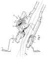
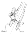
- 1 to 3 is the upper end of a filler neck 1, the lower end (not shown) of a vehicle fuel tank.
- a filler neck 1 In the upper end of the filler neck 1 an approximately pot-shaped insert 2 is inserted tightly, which reduced an opening 3 at its lower end Diameter for the passage of the filling tube 4 one Has nozzle (not shown).
- the opening 3 can be closed with the aid of a flap 5 hinged on one side, which by a spring 6 against the underside Edge of the opening is biased.
- the upper end of the filler neck 1 together with the insert 2 passes through with the interposition of a sealing collar 7 Opening 8 in a recessed area of a vehicle body 9.
- the reset area can be identified by an appropriate Body flap (not shown) are covered.
- a pressure finger 10 articulated which with Using an actuator 11 against the bottom of the Flap 5 can be acted upon (see Fig. 3).
- the pressure finger 10 is a two-armed lever in the example shown, and the Actuating device 11 comprises a pivotable, on its End provided with a spring-loaded pressure roller 12 Cam 13, which on the one lever arm of the pressure finger 10th presses and its other lever arm against the bottom of the Flap 5 presses (Fig. 3).
- the pressure finger shown and actuator construction is any other Form of pressing device for the flap 5 possible.
- the cam 13 is pivoted via a shaft 14 which can be obtained from a suitable e.g. electrical, hydraulic or pneumatic (not shown) servo motor driven becomes. Manual operation is also possible.
- the flap 5 For a possible after pulling off the filling pipe 4 above the flap 5 remaining fuel excess in the Letting the tank drain out protrudes into the movement path 15 of the Flap 5 in the area before its closed position has a locking projection 16.
- the locking projection 16 is by a radially inward directed grooves in a spring tongue 17 formed on the edge the opening 3 is clamped in the axial direction.
- the locking device combines all for the construction of one ORVR system required fluid circuit elements and still some more necessary in connection with vehicle tanks Elements, as explained in more detail below.
- the drive shaft 14 of the actuator 11 is in the example shown the control shaft of a 5/2-way valve 19, which contains a combined rotary and face slide 19 '.
- the rotary and face slide 19 ' has a control plate 20, which are arranged centrally around the shaft 14 Control holes 21 to 23 is provided, which with connection holes 24 to 26 in a fixed, on the control plate 20th brought into alignment (not shown) end plate can be.
- the face plate is part of a rotary and slide valve 19 'in stock, towards the filler neck interior open socket 27, which in the wall of the filler neck 1 is formed.
- connection holes 24 to 26 and the connection opening 30 are with respect to the connection holes 24 to 26 and the connection opening 30 arranged so that in the relief position shown in FIGS. 1 and 2 Flap 5, the connection holes 24 to 26 closed and the Connection opening 30 is connected to the inside of the filler neck, whereas in the loading position shown in FIG Flap 5, the connection holes 24 to 26 with the filler neck inside are connected and the connection opening 30 is closed is.
- connection opening 30 is a collecting line for fuel vapors connected, which to a fuel vapor receiver (not shown) leads with an activated carbon filter to the absorption of Is equipped with fuel vapors.
- the collecting container is during operation of the vehicle from combustion supply gases which flushes the fuel residues from the Detach the activated carbon filter and incinerate it.
- the Components and the functionality of this system are the Known specialist.
- the connection opening 30 and the subsequent The collecting line has a sufficiently large flow cross-section, around the amount of fuel vapor generated during refueling (Fig. 1) to be able to dissipate.
- connection hole is 24 with a second one leading to the collecting container Collection line of smaller flow cross-section connected.
- a rollover valve is switched on in the second collecting line. The rollover valve closes under gravity at one Rollover and prevents fuel from escaping via the fuel vapor collecting line and the collecting container.
- connection bores 25 and 26 serve for the Connect one from the top of the vehicle tank Pressure equalization line and one from a gas collection room overflow line outgoing from the top of the vehicle tank.
- the pressure compensation line (connection bore 25) is in driving mode (Fig. 3) over the filler neck interior and the second Collection line connected to the fuel vapor collection container.
- the function of the overfill line (connection bore 26) is known to the expert; it is closed during the refueling process and allows an air supply to be built up in the gas collection space of the vehicle tank. After the refueling process the air supply is vented into the upper end of the filler neck, so that fuel runs into the tank in the filler neck.
- valve functions described can be not only with the help of the shown turning and Slide valve achieve, rather any, multi-way valve known in the art can be used.
- the Invention is also suitable for applications in which an overfill line is dispensed with, in which case a corresponding one reduced multi-way valve is used.
- the connection holes for the pressure compensation line (25) and the second collecting line (24) could also be used directly while driving, i.e. without intermediate connection via the filler neck inside, be connected to each other.
Landscapes
- Engineering & Computer Science (AREA)
- Life Sciences & Earth Sciences (AREA)
- Sustainable Development (AREA)
- Sustainable Energy (AREA)
- Chemical & Material Sciences (AREA)
- Combustion & Propulsion (AREA)
- Transportation (AREA)
- Mechanical Engineering (AREA)
- Cooling, Air Intake And Gas Exhaust, And Fuel Tank Arrangements In Propulsion Units (AREA)
- Nozzles (AREA)
Abstract
Description
Die vorliegende Erfindung betrifft eine Verschlußvorrichtung
gemäß dem Oberbegriff des Anspruchs 1. Eine derartige Vorrichtung
ist aus der DE-A-43 43 498 bekannt.The present invention relates to a closure device
according to the preamble of
Derzeit müssen Verschlußvorrichtungen für Fahrzeugtank-Einfüllstutzen mit zusätzlichen, gesonderten Fluidschaltungselementen kombiniert werden, um alle Funktionen und Betriebszustände eines Fahrzeugtanks abzudecken. Beispielsweise wird ein Unter- bzw. Überdruckventil benötigt, um den Fahrzeugtank zwecks Druckausgleichs zu Be- oder Entlüften. Verantwortungsbewußter Umgang mit der Umwelt und neuere gesetzliche Anforderungen haben zudem die Entwicklung sogenannter ORVR-Systeme vorangetrieben (Onboard Refuelling Vapor Recovery Systems), mit welchen die beim Betanken auftretenden Kraftstoffdämpfe - unabhängig von einer allfälligen Absaugung über die Gaspendelleitung der Zapfsäule - sowie die im Fahrbetrieb über das Überdruckventil entweichenden Dämpfe am Fahrzeug ("on board") in einem mit einem Aktivkohlefilter ausgestatteten Auffangbehälter aufgefangen werden. Der Auffangbehälter wird im Fahrbetrieb von den Verbrennungszufuhrgasen durchspült, welche die Kraftstoffrückstände aus dem Aktivkohlefilter herauslösen und der Verbrennung zuführen. Es sind daher weitere Ventile erforderlich, welche beim Betanken entsprechende Absaug- bzw. Auffangöffnungen und im Fahrbetrieb entsprechende Druckausgleichsöffnungen freigeben.Currently, closure devices for vehicle tank filler necks are required with additional, separate fluid circuit elements can be combined to all functions and operating states of a vehicle tank. For example, a Vacuum or pressure relief valve required to the vehicle tank to equalize pressure for ventilation. Responsible Dealing with the environment and newer legal requirements have also driven the development of so-called ORVR systems (Onboard Refueling Vapor Recovery Systems), with which the fuel vapors that occur during refueling - regardless of any suction via the Gas suspension line of the petrol pump - as well as that when driving vapors escaping the pressure relief valve on the vehicle ("on board ") in a collecting container equipped with an activated carbon filter to be caught. The collecting container is in the Flushing driving operation of the combustion supply gases, which remove the fuel residue from the activated carbon filter and incinerate it. Additional valves are therefore required which appropriate suction or Collection openings and corresponding pressure equalization openings during driving release.
Neueste Vorschriften verlangen überdies einen vollkommen drucklosen Betrieb des Fahrzeugtanks, um die Emission von Kraftstoffdämpfen noch weiter zu reduzieren. Die bisher verwendeten Über- und Unterdruckventile für die Druckausgleichsverbindung zum Auffangbehälter können daher nicht mehr verwendet werden und müssen durch gesonderte Schaltventile ersetzt werden, welche die Druckausgleichsverbindung im Fahrbetrieb freigeben.The latest regulations also require you completely depressurized operation of the vehicle tank to reduce the emission of Reduce fuel vapors even further. The previously used Overpressure and underpressure valves for the pressure compensation connection can therefore no longer be used for the collection container are and must be replaced by separate switching valves, which release the pressure compensation connection while driving.
Der bereits weitverbreitete Einsatz eines sogenannten Überfüllventiles, welches ein Überfüllen des Tankes bis in den Einfüllstutzen hinein verhindert, erhöht die Anzahl der Fluidschaltungselemente noch weiter. Ein von der Klappe betätigtes Überfüllventil ist z.B. aus der EP-A-0 464 420 bekannt.The already widespread use of a so-called Overfill valves, which overfill the tank into the Prevents filler neck into it, increases the number of fluid circuit elements further. One operated by the flap Overfill valve is e.g. known from EP-A-0 464 420.
Die Erfindung setzt sich zum Ziel, eine Verschlußvorrichtung der einleitend genannten Art so weiterzubilden, daß sie alle für die Funktionsweise eines Fahrzeugtanks erforderlichen Fluidschaltungselemente enthält. Dieses Ziel wird erfindungsgemäß dadurch erreicht, daß das Mehrwegeventil in einer anderen Stellung den Einfüllstutzen unterhalb der Klappe mit einer weiteren, zum Auffangbehälter führenden Auffangleitung größeren Strömungsquerschnittes verbindet, daß die Klappe zusätzlich mit Hilfe einer Anpreßeinrichtung in Schließrichtung belastbar ist, und daß die Betätigungseinrichtung das Mehrwegeventil in der Belastungsstellung der Klappe in die genannte eine Stellung steuert, hingegen in der Entlastungsstellung der Klappe in die genannte andere Stellung steuer.The invention aims to provide a closure device of the type mentioned in the introduction so that they all necessary for the functioning of a vehicle tank Contains fluid circuit elements. This goal is achieved according to the invention achieved in that the multi-way valve in another Position the filler neck below the flap with a further, larger collecting line leading to the collecting container Flow cross-section connects that the flap with Can be loaded in the closing direction with the help of a pressure device, and that the actuator the multi-way valve in the Load position of the flap in said one position controls, however, in the relief position of the flap in the other position mentioned tax.
Die erfindungsgemäße Verschlußvorrichtung vereint die Funktionen eines Einfüllstutzenverschlusses, eines ORVR-Ventiles und eines Druckausgleichventiles, die gemeinsam mit der Freigabe bzw. dem Verschließen der Klappe gesteuert werden, welche aufgrund der Anpreßeinrichtung selbst als dichter Stutzenverschluß dient.The closure device according to the invention combines the Functions of a filler neck closure, an ORVR valve and a pressure compensation valve, which together with the Release or closing the flap can be controlled, which itself due to the pressure device as a denser Neck closure serves.
Gemäß einer besonders bevorzugten Ausführungsform der Erfindung wird vorgesehen, daß das Mehrwegeventil in der genannten einen Stellung den Einfüllstutzen unterhalb der Klappe mit einer von einem Gasauffangraum des Fahrzeugtankes ausgehenden Überfülleitung verbindet. Dadurch wird auch die Funktion eines Überfüllventiles integriert.According to a particularly preferred embodiment of the invention it is provided that the multi-way valve in the above one position with the filler neck below the flap one starting from a gas collection space of the vehicle tank Overfill line connects. This also functions as a Overfill valves integrated.
Eine weitere vorteilhafte Ausführungsform der Erfindung zeichnet sich dadurch aus, daß das Mehrwegeventil ein kombiniertes Dreh- und Planschieberventil ist, wobei die genannte weitere Auffangleitung am Umfang, hingegen die Druckausgleichsleitung, die genannte eine Auffangleitung und gegebenenfalls die Überfülleitung in der Stirnplatte einer den Dreh- und Planschieber lagernden, zum Einfüllstutzen hin offenen Buchse münden. Diese Konstruktion berücksichtigt den Platzbedarf der Steueröffnung der großdurchmeßrigen ersten Auffangleitung, welche die beim Tanken anfallenden Kraftstoffdämpfe ableiten muß. Another advantageous embodiment of the invention is characterized in that the multi-way valve is a combined Rotary and face slide valve is, the said additional collecting line on the circumference, on the other hand the pressure compensation line, the said a collecting line and if necessary the overfill pipe in the front plate of the rotary and face slide open socket towards the filler neck. This construction takes into account the space requirements of the Control opening of the large-diameter first collecting line, which derive the fuel vapors generated during refueling got to.
Besonders vorteilhaft ist dabei, wenn bei einer Verschlußvorrichtung, bei welcher die Betätigungseinrichtung einen am Anpreßfinger angreifenden Nocken aufweist, der Nocken auf der Betätigungswelle des Dreh- und Planschiebers sitzt, was eine kompakte Anordnung ergibt.It is particularly advantageous if, in the case of a closure device, in which the actuator on Pressing finger attacking cam, the cam on the Actuating shaft of the rotary and face slide sits what a compact arrangement results.
Die Erfindung wird nachstehend an Hand eines in den Zeichnungen
dargestellten Ausführungsbeispieles näher erläutert. In
den Zeichnungen zeigen die
Fig. 1 bis 3 die Verschlußvorrichtung im Längsschnitt während
des Tankvorganges, am Ende des Tankvorganges und im Fahrbetrieb.The invention is explained below with reference to an embodiment shown in the drawings. In the drawings, the
Fig. 1 to 3, the closure device in longitudinal section during the refueling process, at the end of the refueling process and while driving.
In den Fig. 1 bis 3 ist das obere Ende eines Einfüllstutzens
1 gezeigt, dessen (nicht dargestelltes) unteres Ende zu
einem Fahrzeug-Kraftstofftank führt. In das obere Ende des Einfüllstutzens
1 ist ein etwa topfförmiger Einsatz 2 dicht eingesetzt,
welcher an seinem unteren Ende eine Öffnung 3 verringerten
Durchmessers für den Durchtritt des Füllrohres 4 einer
(nicht weiter dargestellten) Zapfpistole aufweist. Die Öffnung
3 ist mit Hilfe einer einseitig angelenkten Klappe 5 verschließbar,
welche durch eine Feder 6 gegen den unterseitigen
Rand der Öffnung vorgespannt ist.1 to 3 is the upper end of a
Das obere Ende des Einfüllstutzens 1 mitsamt dem Einsatz 2
durchsetzt unter Zwischenschaltung einer Dichtmanschette 7 eine
Öffnung 8 in einem zurückgesetzten Bereich einer Fahrzeugkarosserie
9. Der zurückgesetzte Bereich kann durch eine entsprechende
(nicht dargestellte) Karosserieklappe abgedeckt werden.The upper end of the
Zum dichten Verschließen der Öffnung 3 im Fahrbetrieb ist
neben der Klappe 5 ein Anpreßfinger 10 angelenkt, welcher mit
Hilfe einer Betätigungseinrichtung 11 gegen die Unterseite der
Klappe 5 beaufschlagbar ist (siehe Fig. 3). Der Anpreßfinger 10
ist bei dem gezeigten Beispiel ein zweiarmiger Hebel, und die
Betätigungseinrichtung 11 umfaßt einen verschwenkbaren, an seinem
Ende mit einer federbelasteten Andruckrolle 12 versehenen
Nocken 13, welcher auf den einen Hebelarm des Anpreßfingers 10
drückt und dessen anderen Hebelarm gegen die Unterseite der
Klappe 5 preßt (Fig. 3). Anstelle der gezeigten Anpreßfinger-
und Betätigungseinrichtungskonstruktion ist auch jede andere
Form von Anpreßeinrichtung für die Klappe 5 möglich.To seal the opening 3 while driving
next to the flap 5 a
Das Verschwenken des Nockens 13 erfolgt über eine Welle
14, die von einem geeigneten, z.B. elektrischen, hydraulischen
oder pneumatischen (nicht dargestellten) Servomotor angetrieben
wird. Auch eine Handbetätigung ist möglich.The
Um einen allfälligen, nach dem Abziehen des Füllrohres 4
oberhalb der Klappe 5 verbleibenden Kraftstoffüberschuß in den
Tank abfließen zu lassen, ragt in die Bewegungsbahn 15 der
Klappe 5 im Bereich vor ihrer Schließstellung ein Rastvorsprung
16. Der Rastvorsprung 16 wird durch eine radial einwärts
gerichtete Riefe in einer Federzunge 17 gebildet, die am Rand
der Öffnung 3 in Axialrichtung eingespannt ist. Durch das Einführen
des Füllrohres 4 (Fig. 1) wird die Klappe 5 an dem Rastvorsprung
16 vorbeigedrückt, wobei die Federzunge 17 elastisch
ausweicht. Beim Abziehen des Füllrohres 4 nach beendetem Tankvorgang,
wenn der Anpreßfinger 10 noch nicht betätigt ist
(Fig. 2), liegt die Klappe 5 vor dem Erreichen ihrer Schließstellung
am Rastvorsprung 16 auf, so daß ein kleiner Spalt 18
für den Ablauf des Restkraftstoffes verbleibt.For a possible after pulling off the
Die Verschlußvorrichtung vereint alle für den Aufbau eines
ORVR-Systems erforderlichen Fluidschaltungselemente und noch
einige weitere, im Zusammenhang mit Fahrzeugtanks notwendige
Elemente, wie im nachstehenden ausführlicher erläutert wird.
Die Antriebswelle 14 der Betätigungseinrichtung 11 ist bei dem
gezeigten Beispiel die Steuerwelle eines 5/2-Wegeventiles 19,
welches einen kombinierten Dreh- und Planschieber 19' enthält.
Der Dreh- und Planschieber 19' weist eine Steuerplatte 20 auf,
die mit zentrisch um die Welle 14 herum angeordneten
Steuerbohrungen 21 bis 23 versehen ist, welche mit Anschlußbohrungen
24 bis 26 in einer feststehenden, an der Steuerplatte 20
anliegenden (nicht gezeigten) Stirnplatte in Ausrichtung gebracht
werden können. Die Stirnplatte ist Teil einer den Dreh-
und Planschieber 19' lagernden, zum Einfüllstutzeninneren hin
offenen Buchse 27, welche in der Wandung des Einfüllstutzens 1
ausgeformt ist.The locking device combines all for the construction of one
ORVR system required fluid circuit elements and still
some more necessary in connection with vehicle tanks
Elements, as explained in more detail below.
The
Am Umfang der Steuerplatte 20 ragt eine halbzylindermantelförmige
Schürze 28 hoch, in der eine radiale Steueröffnung
29 ausgespart ist, welche mit einer Anschlußöffnung 30 am
Umfang der Buchse 27 ausgerichtet werden kann.A semicylinder jacket-shaped protrudes from the periphery of the control plate 20
Apron 28 high, in the
Die Steuerbohrungen 21 bis 23 und die Steueröffnung 29 des
Dreh- und Planschiebers 19' sind bezüglich der Anschlußbohrungen
24 bis 26 und der Anschlußöffnung 30 so angeordnet, daß in
der in den Fig. 1 und 2 gezeigten Entlastungsstellung der
Klappe 5 die Anschlußbohrungen 24 bis 26 verschlossen und die
Anschlußöffnung 30 mit dem Einfüllstutzeninneren verbunden ist,
wogegen in der in Fig. 3 gezeigten Belastungsstellung der
Klappe 5 die Anschlußbohrungen 24 bis 26 mit dem Einfüllstutzeninneren
verbunden sind und die Anschlußöffnung 30 verschlossen
ist.The
Die Belegung der Anschlußbohrungen 24 bis 26 und der
Anschlußöffnung 30 ist wie folgt. An die Anschlußöffnung 30 ist
eine Auffangleitung für Kraftstoffdämpfe angeschlossen, welche
zu einem (nicht dargestellten) Kraftstoffdampf-Auffangbehälter
führt, der mit einem Aktivkohlefilter zur Absorption der
Kraftstoffdämpfe ausgestattet ist. Der Auffangbehälter wird
während des Betriebes des Fahrzeuges von Verbrennungszufuhrgasen
durchspült, welche die Kraftstoffrückstände aus dem
Aktivkohlefilter herauslösen und der Verbrennung zuführen. Die
Komponenten und die Funktionsweise dieses Systems sind dem
Fachmann bekannt. Die Anschlußöffnung 30 und die anschließende
Auffangleitung haben ausreichend großen Strömungsquerschnitt,
um die während des Tankens (Fig. 1) anfallende Kraftstoffdampfmenge
abführen zu können.The assignment of the
Für den Fahrbetrieb (Fig. 3) wird dieser großdurchmeßrige Verbindungsweg verschlossen und ein Verbindungweg mit kleinerem Strömungsquerschnitt errichtet. Zu diesem Zweck ist die Anschlußbohrung 24 mit einer zweiten zum Auffangbehälter führenden Auffangleitung kleineren Strömungsquerschnittes verbunden. In die zweite Auffangleitung ist ein Überrollventil eingeschaltet. Das Überrollventil schließt schwerkraftgesteuert bei einem Fahrzeugüberschlag und verhindert ein Austreten des Kraftstoffes über die Kraftstoffdampf-Auffangleitung und den Auffangbehälter.For driving operation (Fig. 3) this is large-diameter Connection path closed and a connection path with a smaller one Flow cross section established. For this purpose the connection hole is 24 with a second one leading to the collecting container Collection line of smaller flow cross-section connected. A rollover valve is switched on in the second collecting line. The rollover valve closes under gravity at one Rollover and prevents fuel from escaping via the fuel vapor collecting line and the collecting container.
Die weiteren Anschlußbohrungen 25 und 26 dienen für den Anschluß einer von der Oberseite des Fahrzeugtanks ausgehenden Druckausgleichsleitung sowie einer von einem Gasauffangraum an der Oberseite des Fahrzeugtankes ausgehenden Überfülleitung. Die Druckausgleichsleitung (Anschlußbohrung 25) ist im Fahrbetrieb (Fig. 3) über das Einfüllstutzeninnere und die zweite Auffangleitung mit dem Kraftstoffdampf-Auffangbehälter verbunden. Die Funktion der Überfülleitung (Anschlußbohrung 26) ist dem Fachmann bekannt; sie ist während des Tankvorganges geschlossen und erlaubt den Aufbau eines Luftvorrates im Gasauffangraum des Fahrzeugtankes. Nach Beendigung des Tankvorganges wird der Luftvorrat in das obere Ende des Einfüllstutzens entlüftet, so daß Kraftstoff im Einfüllstutzen in den Tank rinnt.The further connection bores 25 and 26 serve for the Connect one from the top of the vehicle tank Pressure equalization line and one from a gas collection room overflow line outgoing from the top of the vehicle tank. The pressure compensation line (connection bore 25) is in driving mode (Fig. 3) over the filler neck interior and the second Collection line connected to the fuel vapor collection container. The function of the overfill line (connection bore 26) is known to the expert; it is closed during the refueling process and allows an air supply to be built up in the gas collection space of the vehicle tank. After the refueling process the air supply is vented into the upper end of the filler neck, so that fuel runs into the tank in the filler neck.
Selbstverständlich lassen sich die beschriebenen Ventilfunktionen nicht nur mit Hilfe des dargestellten Dreh- und Planschieberventiles erzielen, vielmehr kann jedes beliebige, in der Technik bekannte Mehrwegeventil eingesetzt werden. Die Erfindung eignet sich auch für Anwendungsfälle, in denen auf eine Überfülleitung verzichtet wird, in welchem Fall ein entsprechend reduziertes Mehrwegeventil eingesetzt wird. Die Anschlußbohrungen für die Druckausgleichsleitung (25) und die zweite Auffangleitung (24) könnten im Fahrbetrieb auch direkt, d.h. ohne Zwischenverbindung über das Einfüllstutzeninnere, miteinander verbunden werden.Of course, the valve functions described can be not only with the help of the shown turning and Slide valve achieve, rather any, multi-way valve known in the art can be used. The Invention is also suitable for applications in which an overfill line is dispensed with, in which case a corresponding one reduced multi-way valve is used. The connection holes for the pressure compensation line (25) and the second collecting line (24) could also be used directly while driving, i.e. without intermediate connection via the filler neck inside, be connected to each other.
Claims (4)
- Closure device for the filler neck (1) of a vehicle fuel tank, comprising an opening (3) for the passage of the filling hose (4) of a fuel pump nozzle, provided with a flap (5) which is pretensioned against the underside edge of the opening (3) by means of a spring (6), and a multiway valve (19) which, in a first position, connects a pressure-compensating line (25) connected to the vehicle fuel tank to a receiving line (24) leading to a fuel vapour receiver and provided with a roll-over valve, characterised in that, in a second position, the multiway valve (19) connects the filler neck (1) below the flap (5) to another receiving line (30) with a larger flow cross section leading to the receiver, that the flap (5) can additionally be loaded in the closing direction with the aid of a pressure means (10, 11) and that the pressure means (10, 11) directs the multiway valve (19) into the said first position in the loading position of the flap (5) and, on the other hand, into the said second position in the relief position of the flap (5).
- Closure device according to claim 1, characterised in that the multiway valve (19) connects the filler neck (1) below the flap (5) to an overfill line (26) departing from a gas-receiving space in the vehicle fuel tank in the said first position.
- Closure device according to claim 1 or claim 2, characterised in that the multiway valve (19) is a combined rotary slide and cross-slide valve, the said further receiving line (30) on the circumference and, on the other hand, the pressure-compensating line (25), the said first receiving line (24) and possibly the overfill line (26) opening into the end plate of a bushing (27) supporting the rotary and cross slide (19') of the valve and open towards the filler neck (1).
- Closure device according to claim 3, in which the pressure means (11) has a cam (13) engaging a pressure finger, characterised in that the cam (13) is secured to the actuating shaft (14) of the rotary and cross slide (19').
Applications Claiming Priority (4)
| Application Number | Priority Date | Filing Date | Title |
|---|---|---|---|
| AT189495 | 1995-11-21 | ||
| AT0189495A AT403142B (en) | 1995-11-21 | 1995-11-21 | LOCKING DEVICE FOR A VEHICLE TANK FILLER |
| AT1894/95 | 1995-11-21 | ||
| PCT/AT1996/000231 WO1997018966A1 (en) | 1995-11-21 | 1996-11-21 | Closure device for a vehicle tank filler pipe |
Publications (2)
| Publication Number | Publication Date |
|---|---|
| EP0804348A1 EP0804348A1 (en) | 1997-11-05 |
| EP0804348B1 true EP0804348B1 (en) | 2000-02-23 |
Family
ID=3523319
Family Applications (1)
| Application Number | Title | Priority Date | Filing Date |
|---|---|---|---|
| EP96938844A Expired - Lifetime EP0804348B1 (en) | 1995-11-21 | 1996-11-21 | Closure device for a vehicle tank filler pipe |
Country Status (5)
| Country | Link |
|---|---|
| US (1) | US5921424A (en) |
| EP (1) | EP0804348B1 (en) |
| AT (2) | AT403142B (en) |
| DE (1) | DE59604493D1 (en) |
| WO (1) | WO1997018966A1 (en) |
Families Citing this family (18)
| Publication number | Priority date | Publication date | Assignee | Title |
|---|---|---|---|---|
| AT406850B (en) * | 1998-10-12 | 2000-09-25 | Tesma Motoren Getriebetechnik | DRIVING DEVICE FOR A CLOSING DEVICE OF A VEHICLE TANK FILLING CONNECTOR |
| DE19934422B4 (en) * | 1999-07-22 | 2006-06-01 | Audi Ag | filler pipe |
| DE19956349B4 (en) * | 1999-11-24 | 2005-03-31 | Blau Kunststofftechnik Zweigniederlassung Der Tesma Europa Gmbh | tank closure |
| AT4281U1 (en) * | 2000-03-31 | 2001-05-25 | Tesma Motoren Getriebetechnik | FILLING PIPE |
| DE10326587A1 (en) * | 2003-06-13 | 2005-01-05 | Gresens, Dieter, Rojales | Device and method for securing a tank contents |
| DE10331073B4 (en) * | 2003-07-09 | 2007-07-12 | Alfmeier Präzision AG Baugruppen und Systemlösungen | Vehicle tank with a filler pipe |
| US7096899B2 (en) * | 2003-10-04 | 2006-08-29 | Alfmeier Prazision Ag Baugruppen | Automatic tank closure for a fuel tank |
| FR2861655B1 (en) * | 2003-10-31 | 2006-01-06 | Inergy Automotive Systems Res | DEVICE FOR FILLING A FILLING TUBE FROM A LIQUID TANK, TANK EQUIPPED WITH SUCH A DEVICE AND MOTOR VEHICLE COMPRISING SUCH A TANK |
| DE102004011753B3 (en) * | 2004-03-09 | 2005-09-29 | Tesma Europa Gmbh | filler cap |
| ATE409139T1 (en) * | 2005-02-10 | 2008-10-15 | Gerdes Gmbh | LID-LESS LOCKABLE SOCKET CLOSURE FOR A FILLER NECK OF A TANK OF A MOTOR VEHICLE |
| US7055557B1 (en) * | 2005-03-03 | 2006-06-06 | Eaton Corporation | Dual seal filler neck with air relief valve |
| US8371346B2 (en) * | 2010-08-09 | 2013-02-12 | Robert W. Schmidt | Apparatus for capturing fuel spillage and nozzle drip during refueling of a vehicle |
| DE102013100076A1 (en) * | 2013-01-07 | 2014-07-10 | Veritas Ag | filling head |
| DE202013103709U1 (en) * | 2013-08-15 | 2014-11-18 | KÖHLER AUTOMOBILTECHNIK GmbH | Ventilation system for fuel tanks |
| JP6128084B2 (en) * | 2014-09-09 | 2017-05-17 | トヨタ自動車株式会社 | Fuel tank fueling part structure |
| JP6561893B2 (en) | 2016-04-01 | 2019-08-21 | 豊田合成株式会社 | Fuel supply device |
| JP6426660B2 (en) * | 2016-06-21 | 2018-11-21 | 本田技研工業株式会社 | Fuel supply pipe structure |
| JP6488272B2 (en) * | 2016-12-15 | 2019-03-20 | 本田技研工業株式会社 | Fuel supply pipe oil supply structure |
Family Cites Families (8)
| Publication number | Priority date | Publication date | Assignee | Title |
|---|---|---|---|---|
| JPH081134Y2 (en) * | 1987-12-09 | 1996-01-17 | オーエム工業株式会社 | Car refueling pipe |
| US5056570A (en) * | 1990-03-26 | 1991-10-15 | Stant Inc. | Capless vehicle refueling system |
| DE4021218A1 (en) * | 1990-07-04 | 1992-01-09 | Blau Kg Kraftfahrzeugtech | TANK FUEL TUBE FOR A FUEL TANK |
| US5103877A (en) * | 1991-04-15 | 1992-04-14 | General Motors Corporation | Vapor-liquid separator for evaporative emissions control system |
| US5271438A (en) * | 1992-06-22 | 1993-12-21 | Stant Manufacturing Inc. | Capless vehicle refueling system with moving fill passageway |
| US5404906A (en) * | 1992-12-21 | 1995-04-11 | Nissan Motor Co., Ltd. | Fuel tank |
| US5437317A (en) * | 1993-02-04 | 1995-08-01 | Om Corporation | Ventilation line opening/closing means of fuel tank |
| AT403141B (en) * | 1995-09-19 | 1997-11-25 | Blau Automobiltechnik Gmbh | LOCKING DEVICE FOR A VEHICLE TANK FILLER |
-
1995
- 1995-11-21 AT AT0189495A patent/AT403142B/en not_active IP Right Cessation
-
1996
- 1996-11-21 WO PCT/AT1996/000231 patent/WO1997018966A1/en not_active Ceased
- 1996-11-21 US US08/875,271 patent/US5921424A/en not_active Expired - Lifetime
- 1996-11-21 DE DE59604493T patent/DE59604493D1/en not_active Expired - Lifetime
- 1996-11-21 AT AT96938844T patent/ATE189876T1/en active
- 1996-11-21 EP EP96938844A patent/EP0804348B1/en not_active Expired - Lifetime
Also Published As
| Publication number | Publication date |
|---|---|
| ATA189495A (en) | 1997-04-15 |
| DE59604493D1 (en) | 2000-03-30 |
| US5921424A (en) | 1999-07-13 |
| AT403142B (en) | 1997-11-25 |
| WO1997018966A1 (en) | 1997-05-29 |
| EP0804348A1 (en) | 1997-11-05 |
| ATE189876T1 (en) | 2000-03-15 |
Similar Documents
| Publication | Publication Date | Title |
|---|---|---|
| AT403142B (en) | LOCKING DEVICE FOR A VEHICLE TANK FILLER | |
| DE3742256C1 (en) | Device for collecting fuel vapors when refueling a fuel tank | |
| DE4012368C2 (en) | ||
| DE10064395C2 (en) | Level control system for a motor vehicle | |
| DE4109337A1 (en) | CAPLESS VEHICLE REFUELING DEVICE | |
| EP0464420A1 (en) | Filler neck for a fuel tank | |
| EP0320643B2 (en) | Fuel tank | |
| DE19911489B4 (en) | Device for controlling fluid flows during refueling | |
| AT407386B (en) | DEVICE FOR CONTROLLING GAS FLOWS AND LIQUID LEVELS IN AN ORVR FUELING SYSTEM | |
| DE19802078B4 (en) | Motor vehicle tank | |
| DE102006004630B4 (en) | Fuel tank | |
| EP1491120A1 (en) | Coupling unit of an espresso machine | |
| EP2031237A1 (en) | Injection nozzle for injecting fuel | |
| EP1165339B1 (en) | Filler neck for the fuel tank of a motor vehicle | |
| EP0843624B1 (en) | Multipurpose valve for a fuel tank filler neck | |
| EP0433586B1 (en) | Extraction system for welding apparatuses using a cooling element | |
| EP1049598B1 (en) | Device for preventing a fuel tank to be overfilled | |
| DE19956582C1 (en) | Ventilation unit for vehicle fuel tank; has directional control valve between ventilation line, operation ventilation unit and refuelling limiting valve and adsorption filter in ventilation line | |
| DE1655032A1 (en) | Braking device for articulated vehicles | |
| DE19642308A1 (en) | Vehicle fuel tank with venting regulator | |
| DE2406843C3 (en) | Pressure equalization arrangement for a vehicle fuel tank | |
| DE4335945A1 (en) | Suction device | |
| DE19500775C1 (en) | Device for ventilating and bleeding vehicle fuel tanks | |
| DE19934422B4 (en) | filler pipe | |
| AT402624B (en) | END PIECE FOR A VEHICLE TANK FILLER CONNECTOR END PIECE FOR A VEHICLE TANK FILLER CONNECTOR |
Legal Events
| Date | Code | Title | Description |
|---|---|---|---|
| PUAI | Public reference made under article 153(3) epc to a published international application that has entered the european phase |
Free format text: ORIGINAL CODE: 0009012 |
|
| 17P | Request for examination filed |
Effective date: 19970708 |
|
| AK | Designated contracting states |
Kind code of ref document: A1 Designated state(s): AT DE FR GB IT |
|
| 17Q | First examination report despatched |
Effective date: 19990119 |
|
| GRAG | Despatch of communication of intention to grant |
Free format text: ORIGINAL CODE: EPIDOS AGRA |
|
| GRAH | Despatch of communication of intention to grant a patent |
Free format text: ORIGINAL CODE: EPIDOS IGRA |
|
| GRAH | Despatch of communication of intention to grant a patent |
Free format text: ORIGINAL CODE: EPIDOS IGRA |
|
| ITF | It: translation for a ep patent filed | ||
| GRAA | (expected) grant |
Free format text: ORIGINAL CODE: 0009210 |
|
| AK | Designated contracting states |
Kind code of ref document: B1 Designated state(s): AT DE FR GB IT |
|
| REF | Corresponds to: |
Ref document number: 189876 Country of ref document: AT Date of ref document: 20000315 Kind code of ref document: T |
|
| GBT | Gb: translation of ep patent filed (gb section 77(6)(a)/1977) |
Effective date: 20000223 |
|
| REF | Corresponds to: |
Ref document number: 59604493 Country of ref document: DE Date of ref document: 20000330 |
|
| ET | Fr: translation filed | ||
| PG25 | Lapsed in a contracting state [announced via postgrant information from national office to epo] |
Ref country code: AT Free format text: LAPSE BECAUSE OF NON-PAYMENT OF DUE FEES Effective date: 20001121 |
|
| PLBE | No opposition filed within time limit |
Free format text: ORIGINAL CODE: 0009261 |
|
| STAA | Information on the status of an ep patent application or granted ep patent |
Free format text: STATUS: NO OPPOSITION FILED WITHIN TIME LIMIT |
|
| 26N | No opposition filed | ||
| REG | Reference to a national code |
Ref country code: GB Ref legal event code: IF02 |
|
| PGFP | Annual fee paid to national office [announced via postgrant information from national office to epo] |
Ref country code: FR Payment date: 20061124 Year of fee payment: 11 |
|
| PGFP | Annual fee paid to national office [announced via postgrant information from national office to epo] |
Ref country code: GB Payment date: 20061127 Year of fee payment: 11 |
|
| PGFP | Annual fee paid to national office [announced via postgrant information from national office to epo] |
Ref country code: IT Payment date: 20061130 Year of fee payment: 11 |
|
| GBPC | Gb: european patent ceased through non-payment of renewal fee |
Effective date: 20071121 |
|
| REG | Reference to a national code |
Ref country code: FR Ref legal event code: ST Effective date: 20080930 |
|
| PG25 | Lapsed in a contracting state [announced via postgrant information from national office to epo] |
Ref country code: GB Free format text: LAPSE BECAUSE OF NON-PAYMENT OF DUE FEES Effective date: 20071121 |
|
| PG25 | Lapsed in a contracting state [announced via postgrant information from national office to epo] |
Ref country code: FR Free format text: LAPSE BECAUSE OF NON-PAYMENT OF DUE FEES Effective date: 20071130 |
|
| PG25 | Lapsed in a contracting state [announced via postgrant information from national office to epo] |
Ref country code: IT Free format text: LAPSE BECAUSE OF NON-PAYMENT OF DUE FEES Effective date: 20071121 |
|
| PGFP | Annual fee paid to national office [announced via postgrant information from national office to epo] |
Ref country code: DE Payment date: 20131121 Year of fee payment: 18 |
|
| REG | Reference to a national code |
Ref country code: DE Ref legal event code: R119 Ref document number: 59604493 Country of ref document: DE |
|
| PG25 | Lapsed in a contracting state [announced via postgrant information from national office to epo] |
Ref country code: DE Free format text: LAPSE BECAUSE OF NON-PAYMENT OF DUE FEES Effective date: 20150602 |