EP0320617A2 - Régulateur pour pompes à injection de combustible - Google Patents
Régulateur pour pompes à injection de combustible Download PDFInfo
- Publication number
- EP0320617A2 EP0320617A2 EP19880118672 EP88118672A EP0320617A2 EP 0320617 A2 EP0320617 A2 EP 0320617A2 EP 19880118672 EP19880118672 EP 19880118672 EP 88118672 A EP88118672 A EP 88118672A EP 0320617 A2 EP0320617 A2 EP 0320617A2
- Authority
- EP
- European Patent Office
- Prior art keywords
- lever
- rocker arm
- spring
- speed
- stop
- Prior art date
- Legal status (The legal status is an assumption and is not a legal conclusion. Google has not performed a legal analysis and makes no representation as to the accuracy of the status listed.)
- Withdrawn
Links
Images

Classifications
-
- F—MECHANICAL ENGINEERING; LIGHTING; HEATING; WEAPONS; BLASTING
- F02—COMBUSTION ENGINES; HOT-GAS OR COMBUSTION-PRODUCT ENGINE PLANTS
- F02D—CONTROLLING COMBUSTION ENGINES
- F02D1/00—Controlling fuel-injection pumps, e.g. of high pressure injection type
- F02D1/02—Controlling fuel-injection pumps, e.g. of high pressure injection type not restricted to adjustment of injection timing, e.g. varying amount of fuel delivered
- F02D1/04—Controlling fuel-injection pumps, e.g. of high pressure injection type not restricted to adjustment of injection timing, e.g. varying amount of fuel delivered by mechanical means dependent on engine speed, e.g. using centrifugal governors
- F02D1/045—Controlling fuel-injection pumps, e.g. of high pressure injection type not restricted to adjustment of injection timing, e.g. varying amount of fuel delivered by mechanical means dependent on engine speed, e.g. using centrifugal governors characterised by arrangement of springs or weights
-
- F—MECHANICAL ENGINEERING; LIGHTING; HEATING; WEAPONS; BLASTING
- F02—COMBUSTION ENGINES; HOT-GAS OR COMBUSTION-PRODUCT ENGINE PLANTS
- F02D—CONTROLLING COMBUSTION ENGINES
- F02D1/00—Controlling fuel-injection pumps, e.g. of high pressure injection type
- F02D1/02—Controlling fuel-injection pumps, e.g. of high pressure injection type not restricted to adjustment of injection timing, e.g. varying amount of fuel delivered
- F02D1/08—Transmission of control impulse to pump control, e.g. with power drive or power assistance
- F02D1/10—Transmission of control impulse to pump control, e.g. with power drive or power assistance mechanical
-
- F—MECHANICAL ENGINEERING; LIGHTING; HEATING; WEAPONS; BLASTING
- F02—COMBUSTION ENGINES; HOT-GAS OR COMBUSTION-PRODUCT ENGINE PLANTS
- F02B—INTERNAL-COMBUSTION PISTON ENGINES; COMBUSTION ENGINES IN GENERAL
- F02B2275/00—Other engines, components or details, not provided for in other groups of this subclass
- F02B2275/14—Direct injection into combustion chamber
-
- Y—GENERAL TAGGING OF NEW TECHNOLOGICAL DEVELOPMENTS; GENERAL TAGGING OF CROSS-SECTIONAL TECHNOLOGIES SPANNING OVER SEVERAL SECTIONS OF THE IPC; TECHNICAL SUBJECTS COVERED BY FORMER USPC CROSS-REFERENCE ART COLLECTIONS [XRACs] AND DIGESTS
- Y02—TECHNOLOGIES OR APPLICATIONS FOR MITIGATION OR ADAPTATION AGAINST CLIMATE CHANGE
- Y02T—CLIMATE CHANGE MITIGATION TECHNOLOGIES RELATED TO TRANSPORTATION
- Y02T10/00—Road transport of goods or passengers
- Y02T10/10—Internal combustion engine [ICE] based vehicles
- Y02T10/12—Improving ICE efficiencies
Definitions
- the invention relates to a speed controller for fuel injection pumps according to the preamble of claim 1.
- an adjustable control spring acts against a speed-dependent force on a one-armed tensioning lever.
- the tensioning lever is connected to the starting lever, which is coupled to a quantity adjustment element of the fuel injection pump.
- the start lever In a first adjustment range, the start lever is pivoted by the speed-dependent force against the force of a starting spring supported on the rocker arm towards the rocker arm by the amount limited by a stop.
- the start and finger lever are pivoted against the force of a control spring.
- the problem set out in the aforementioned prior art is essentially solved in a technically simple manner.
- the invention is based on the idea of shortening the control slide travel and therefore the associated conveying end below the control slide travel at full load and in the final phase of the starting process to raise the slide travel to that at full load. This is advantageously achieved by lowering the injection quantity that is too high at low engine speeds with an otherwise identical injection pump.
- FIG. 1 shows the first example of a speed controller
- Figure 2 shows a further embodiment
- Figure 3 shows a third embodiment
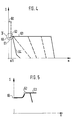
- Figure 4 shows the controller map for an all speed control
- FIG. 5 shows a greatly enlarged detail of the control map according to section 5 in FIG. 4.
- the speed controller according to the invention shown in FIG. 1 consists of a speed controller installed in a reciprocating piston distributor injection pump.
- the fuel injection pump has a pump piston 1 which delimits a pump working space and which, in a known manner, is set into a reciprocating and simultaneously rotating movement by a cam disk, not shown and driven by the internal combustion engine, against the force of a return spring, also not shown .
- the pump piston 1 On the pump piston 1 is arranged in the longitudinal direction of the pump piston displaceable, designed as a ring slide quantity adjustment element 2, which opens an outlet opening 4 of a discharge channel 3 connected to the pump work chamber in the course of the pressure stroke of the pump piston 1 depending on the position of the ring slide sooner or later, and thus that Conveying end or the delivery quantity delivered by the pump piston 1 into a pressure line, not shown, is determined.
- the fuel that flows out after being opened flows back into a suction chamber.
- the axial position of the quantity adjusting member 2 is controlled in relation to the position of the outlet opening 4 in the pump piston 1 by a one-armed start lever 5 of a speed regulator installed in a suction chamber of the pump serving to supply the pump work space with fuel.
- the controller consists of the start lever 5, a one-arm rocker arm 20 which can be pivoted in the same plane as the start lever, a control spring 25 and an idle spring 32, both of which are articulated to the rocker arm 20 and a speed signal transmitter 11.
- the speed signal transmitter 11 is represented by a not shown Gearbox proportional to the speed of the engine or Pump piston 1 driven and has a support body 12 which receives in a known manner in pocket guided flyweights 13 which engage with nose-shaped pressure arms 14 on the drive-side ends of the on the axis 72 of the speed signal generator 11 of the longitudinally displaceable adjusting sleeve.
- z. B hydraulically or pneumatically actuated actuators that attack at the same point of attack on the start lever 5 into consideration.
- the rocker arm 20 can be rotated about an axis 28 which is fixed to the housing, but which can also be adjustable by being displaced in the longitudinal direction of the pump piston, as indicated by arrows.
- An axis 6 is arranged on the rocker arm 20, to which the start lever is articulated.
- This start lever 5 extends in the direction of quantity adjustment member 2.
- the start lever 5 is cranked and has a spherical pin 9 serving as a driver, which engages in a recess 10 of the quantity adjustment member 2.
- the end 8 of the start lever 5 is therefore cranked to guide it around the axis 28 of the rocker arm 20 at a distance.
- the start spring is a leaf spring which is attached at one end to the start lever 5 and is supported at the other end on the rocker arm 20.
- the rocker arm 20 In the area of the end projecting beyond the axis 6, the rocker arm 20 has a bore 21 through which a bolt 22 is inserted.
- An intermediate spring 24 is arranged between a head 23 of the bolt 22, which bears against the rocker arm 20 in the position shown, and the rocker arm 20.
- a control spring 25 designed as a tension spring, the other end of which is hooked onto a lever 26 limited in its control path by a stop 27.
- an idle spring 32 acts on the rocker arm 20. This is hooked onto a connecting bolt 33.
- the connecting bolt 33 protrudes through a recess 34 in the rocker arm 20 and has a head 39 at the other end, which is designed as a stop.
- the other end of the idle spring 32 is suspended in an adjustment part 40, which is designed as an adjusting lever 15.
- the adjusting lever 15 can be adjusted by means of an adjusting screw 16 to change the preload of the idle spring 32 and works in parallel with the control spring 25.
- the speed-dependent force of the speed signal generator 11 pivots the start lever 5 counterclockwise in the first adjustment range against the force of the control spring 25, start spring 29 and the idle spring 32, as shown in FIG. 1, until the start lever 5 deforms only the start spring 29 on the one designed as a stop Axis 28 of the rocker arm 20 rests.
- the starter lever 5 and rocker arm 20 pivot clockwise about the axis 28 in a second adjustment range.
- Connected to this start lever 5 is the pin 9, which engages in the quantity adjustment element 2.
- the quantity adjustment element 2 is in the starting position of the start lever with a small delivery quantity and is then shifted to more delivery quantity in the first adjustment range, in order then to be adjusted again in the second adjustment range to a lower or constant delivery amount.
- FIG. 4 shows a functional diagram of this speed controller according to the invention, in which the pump speed in revolutions / per minute is shown on the abscissa and the path S of the quantity adjustment element 2 is shown on the ordinate.
- the dashed line of the fuel injection quantity was also drawn for previously known fuel injection pumps in the starting phase, where by ei ner high starting quantity according to point 60 after the start is reduced to full load quantity according to point 62.
- start-the stop head 44 With increasing speed-after start-the stop head 44 first comes to rest against the rocker arm 20. As a result, the stop head 44 against the force of the start spring 29 'to the contact of the first stop 36 may be shifted somewhat and with increasing speed until the stop head 44 on the intermediate lever 35 'moved further. Analogously to the intermediate lever from FIG. 2, the intermediate lever executes a counterclockwise tilt movement around the first stop 36 corresponding to the first adjustment range.
- the change in the path of the quantity adjusting element 2 according to the invention with a “negative starting quantity” is shown as a solid line 61.
- the path change according to the invention of the quantity adjustment path in the case of a “negative starting quantity” is shown again on an enlarged scale in FIG. 5.
- the centrifugal weights 5 are at rest and the adjusting sleeve 7 is in the lowest starting position.
- the start lever 5 and at the same time the quantity adjustment element 2 are pressed into the start position by the start spring 29, which corresponds to the reference point 65 in FIG. If the engine is started, the adjusting sleeve 7 of the speed signal transmitter 11 moves against the start lever 5, which moves against the force of the start spring 29.
- the rocker arm 20 is held by the control spring 25 during this initial movement of the adjusting sleeve 7 of the speed signal transmitter 11, so that the starting lever 5 pivots about the axis 6.
- This pivoting movement of the start lever 5 until it rests on the axis 28 of the rocker arm 20 corresponds to the first adjustment range.
- the quantity adjustment element 2 moves to a greater fuel delivery quantity and, at the end of this first adjustment range, reaches its full-load position indicated by position 63 in FIG. 5, in which the full-load injection quantity is conveyed by the pump piston.
- Starting lever 5 acts from the system on axis 28 like a two-armed lever, that is, with increasing movement of the adjusting sleeve 7 after the starting lever 5 bears against the axis 28, the starting lever 5 moves the quantity adjusting member 2 in the direction of a lower delivery quantity to regulate the fuel injection quantity.
- the speed is reduced when the speed-dependent force set by the pretensioning of the control spring is exceeded.
- the parts corresponding to the first exemplary embodiment are given the same name, and slightly modified parts are provided with an index line.
- This embodiment differs from that shown in FIG. 1 by a changing lever arrangement.
- the rocker arm 20 ' is pivotable about the axis 28.
- the rocker arm 20 ' engages the control spring 25.
- the start lever 5 ' is designed as a two-armed lever and also pivotable about the axis 28.
- One arm of the start lever 5 ' engages the quantity adjustment member 2, while the other arm extends almost parallel to the rocker arm 20'.
- an intermediate lever 35 is articulated to an axis 106, which extends to the axis 28 and between the starter lever 5' and the rocker arm 20 'lying a system for the adjusting sleeve 7.
- the intermediate lever 35 has a first stop 36 and a second stop 37, both of which are associated with the rocker arm 20 'and between which the adjusting sleeve 7 engages on the other side of the intermediate lever 35.
- the first stop 36 after the articulation point on the axis 106 of the intermediate lever 35 is raised compared to a straight connection between the stop 7 and the axis 106, that is to say it is upstream of the rocker arm 20.
- the intermediate lever 5 ' comes first with the first stop 36 and after a tilting movement around this first stop 36 only with its second stop 37 to rest on the rocker arm 20'.
- the start lever 5 ' carries out a pivoting movement counterclockwise away from the rocker arm 20.
- the first stop 36 is arranged on the angled contact surface 31 'of the start lever 5' and designed as a rivet, screw or the like with a corresponding hemispherical rivet head which serves as a stop surface.
- the starting spring 29, which is also designed as a leaf spring, is fastened to the intermediate lever 35 in the region of the first stop 36, the starting spring striving to pivot the intermediate lever 35 in the direction of the adjusting sleeve 7.
- the start lever 5 'and the intermediate lever 35 are initially in a position in which the quantity adjustment member 2 is set such that a fuel quantity below the full-load injection quantity is delivered.
- the start lever 5 'then pivots, moved by the intermediate lever 35 to the quantity adjustment member 2, as described above, to adjust the delivery rate according to full load.
- the full-load fuel injection quantity is then adjusted again.
- FIG. 3 shows a further development of the exemplary embodiment according to FIG. 2, in which the corresponding parts have the same names, modified parts are provided with index lines.
- a U-shaped bent part 42 is arranged at the end of the intermediate lever 35 'in the direction of axis 28 ⁇ .
- a stop bolt 43 is provided with a stop head 44.
- This has a first bearing 45 in a first bore 50 in the intermediate lever 5 ⁇ and a second bearing 46 coaxial with this first bore in a second bore 51 in the opposite cheek 47 of the U-shaped bent part 42.
- the stop bolt 43 has on the stop head opposite end of a stop 48 with which it is held by the starting spring 29 designed as a spiral spring in contact with the outside of the cheek 47.
- the spiral spring surrounds the stop bolt and is supported between the inside of the cheek 47 and the stop head 44.
- FIGS. 2 and 3 show modifications of FIG. 1 with an intermediate lever 35, by means of which the “negative starting quantity” can be set more finely, in particular by large changes in the actuating sleeve with small changes in the quantity of the adjusting element.
Applications Claiming Priority (2)
| Application Number | Priority Date | Filing Date | Title |
|---|---|---|---|
| DE19873743060 DE3743060A1 (de) | 1987-12-18 | 1987-12-18 | Drehzahlregler fuer kraftstoffeinspritzpumpen |
| DE3743060 | 1987-12-18 |
Publications (2)
| Publication Number | Publication Date |
|---|---|
| EP0320617A2 true EP0320617A2 (fr) | 1989-06-21 |
| EP0320617A3 EP0320617A3 (fr) | 1990-05-09 |
Family
ID=6342982
Family Applications (1)
| Application Number | Title | Priority Date | Filing Date |
|---|---|---|---|
| EP88118672A Withdrawn EP0320617A3 (fr) | 1987-12-18 | 1988-11-10 | Régulateur pour pompes à injection de combustible |
Country Status (5)
| Country | Link |
|---|---|
| US (1) | US4920938A (fr) |
| EP (1) | EP0320617A3 (fr) |
| JP (1) | JPH01200027A (fr) |
| KR (1) | KR890010406A (fr) |
| DE (1) | DE3743060A1 (fr) |
Cited By (2)
| Publication number | Priority date | Publication date | Assignee | Title |
|---|---|---|---|---|
| EP0624720A1 (fr) * | 1993-05-14 | 1994-11-17 | Robert Bosch Gmbh | Pompe d'injection de combustible pour moteurs à combustion interne |
| WO2005052342A2 (fr) * | 2003-11-27 | 2005-06-09 | Motorenfabrik Hatz Gmbh & Co. Kg | Regulateur de vitesse pour moteurs a combustion interne stationnaires |
Families Citing this family (4)
| Publication number | Priority date | Publication date | Assignee | Title |
|---|---|---|---|---|
| DE3844452A1 (de) * | 1988-12-31 | 1990-07-05 | Bosch Gmbh Robert | Verteilerkraftstoffeinspritzpumpe fuer brennkraftmaschinen |
| DE4117267A1 (de) * | 1991-05-27 | 1992-12-03 | Bosch Gmbh Robert | Kraftstoffeinspritzpumpe fuer brennkraftmaschinen |
| DE4443114A1 (de) * | 1994-12-03 | 1996-06-05 | Bosch Gmbh Robert | Kraftstoffeinspritzpumpe für Brennkraftmaschinen |
| JP5288636B2 (ja) * | 2010-09-27 | 2013-09-11 | 株式会社クボタ | ディーゼルエンジンの燃料調量装置 |
Citations (5)
| Publication number | Priority date | Publication date | Assignee | Title |
|---|---|---|---|---|
| FR2414628A1 (fr) * | 1978-01-17 | 1979-08-10 | List Hans | Pompe d'injection pour moteur diesel |
| JPS58133428A (ja) * | 1982-02-01 | 1983-08-09 | Nissan Motor Co Ltd | 燃料噴射ポンプの噴射量制御装置 |
| JPS6040734A (ja) * | 1983-08-12 | 1985-03-04 | Nippon Soken Inc | デイ−ゼルエンジンの燃料噴射制御装置 |
| EP0168613A1 (fr) * | 1984-07-13 | 1986-01-22 | Robert Bosch Gmbh | Régulateur de vitesse pour pompe à injection de combustible |
| DE3503034A1 (de) * | 1985-01-30 | 1986-07-31 | Robert Bosch Gmbh, 7000 Stuttgart | Steuereinrichtung fuer kraftstoffeinspritzpumpen von brennkraftmaschinen |
Family Cites Families (6)
| Publication number | Priority date | Publication date | Assignee | Title |
|---|---|---|---|---|
| DE2402374C2 (de) * | 1974-01-18 | 1983-05-26 | Robert Bosch Gmbh, 7000 Stuttgart | Drehzahlregler für Kraftstoffeinspritzpumpen von Brennkraftmaschinen |
| JPS5332239A (en) * | 1976-09-07 | 1978-03-27 | Nippon Denso Co Ltd | Speed regulator of centrifugal type for internal combustion engine |
| DE2802888A1 (de) * | 1978-01-24 | 1979-07-26 | Bosch Gmbh Robert | Drehzahlregler fuer kraftstoffeinspritzpumpen mit einer angleichung der einspritzmenge |
| JPS6131157Y2 (fr) * | 1981-03-12 | 1986-09-10 | ||
| DE3147701A1 (de) * | 1981-12-02 | 1983-06-16 | Robert Bosch Gmbh, 7000 Stuttgart | Stelleinrichtung fuer ein kraftstoffoerdermengenverstellglied einer kraftstoffeinspritzpumpe |
| IT1165500B (it) * | 1983-12-23 | 1987-04-22 | Piaggio & C Spa | Regolatore dell'alimentazione di un motore a ciclo diesel in fase di avviamento |
-
1987
- 1987-12-18 DE DE19873743060 patent/DE3743060A1/de not_active Withdrawn
-
1988
- 1988-11-10 EP EP88118672A patent/EP0320617A3/fr not_active Withdrawn
- 1988-12-07 US US07/280,806 patent/US4920938A/en not_active Expired - Fee Related
- 1988-12-17 KR KR1019880016888A patent/KR890010406A/ko not_active Application Discontinuation
- 1988-12-19 JP JP63318726A patent/JPH01200027A/ja active Pending
Patent Citations (5)
| Publication number | Priority date | Publication date | Assignee | Title |
|---|---|---|---|---|
| FR2414628A1 (fr) * | 1978-01-17 | 1979-08-10 | List Hans | Pompe d'injection pour moteur diesel |
| JPS58133428A (ja) * | 1982-02-01 | 1983-08-09 | Nissan Motor Co Ltd | 燃料噴射ポンプの噴射量制御装置 |
| JPS6040734A (ja) * | 1983-08-12 | 1985-03-04 | Nippon Soken Inc | デイ−ゼルエンジンの燃料噴射制御装置 |
| EP0168613A1 (fr) * | 1984-07-13 | 1986-01-22 | Robert Bosch Gmbh | Régulateur de vitesse pour pompe à injection de combustible |
| DE3503034A1 (de) * | 1985-01-30 | 1986-07-31 | Robert Bosch Gmbh, 7000 Stuttgart | Steuereinrichtung fuer kraftstoffeinspritzpumpen von brennkraftmaschinen |
Non-Patent Citations (2)
| Title |
|---|
| PATENT ABSTRACTS OF JAPAN, Band 7, Nr. 246 (M-253)[1391], 2. November 1983; & JP-A-58 133 428 (NISSAN) 09-08-1983 * |
| PATENT ABSTRACTS OF JAPAN, Band 9, Nr. 168 (M-396)[1891], 13. Juli 1985; & JP-A-60 040 734 (NIPPON JIDOSHA) 04-03-1985 * |
Cited By (3)
| Publication number | Priority date | Publication date | Assignee | Title |
|---|---|---|---|---|
| EP0624720A1 (fr) * | 1993-05-14 | 1994-11-17 | Robert Bosch Gmbh | Pompe d'injection de combustible pour moteurs à combustion interne |
| WO2005052342A2 (fr) * | 2003-11-27 | 2005-06-09 | Motorenfabrik Hatz Gmbh & Co. Kg | Regulateur de vitesse pour moteurs a combustion interne stationnaires |
| WO2005052342A3 (fr) * | 2003-11-27 | 2009-04-02 | Hatz Motoren | Regulateur de vitesse pour moteurs a combustion interne stationnaires |
Also Published As
| Publication number | Publication date |
|---|---|
| US4920938A (en) | 1990-05-01 |
| EP0320617A3 (fr) | 1990-05-09 |
| DE3743060A1 (de) | 1989-06-29 |
| KR890010406A (ko) | 1989-08-08 |
| JPH01200027A (ja) | 1989-08-11 |
Similar Documents
| Publication | Publication Date | Title |
|---|---|---|
| DE2308260C2 (de) | Fliehkraftdrehzahlregler für Einspritzbrennkraftmaschinen | |
| DE2224755C3 (de) | Fliehkraftdrehzahlregler für Einspritzbrennkraftmaschinen | |
| DE2656261C2 (de) | Fliehkraftdrehzahlregler für Einspritzbrennkraftmaschinen | |
| EP0273225B1 (fr) | Pompe d'injection de combustible pour moteurs à combustion interne | |
| EP0168613B1 (fr) | Régulateur de vitesse pour pompe à injection de combustible | |
| EP0320617A2 (fr) | Régulateur pour pompes à injection de combustible | |
| EP0162287B1 (fr) | Pompe d'injection de carburant pour moteurs à combustion interne | |
| DE2838919C2 (de) | Fliehkraftdrehzahlregler für Einspritzbrennkraftmaschinen | |
| DE3145233A1 (de) | Reglersystem | |
| DE2855889A1 (de) | Fliehkraftdrehzahlregler fuer einspritzbrennkraftmaschinen, insbesondere leerlauf-enddrehzahlregler fuer fahrzeugdieselmotoren | |
| DE4129837C2 (de) | Drehzahlregler für Kraftstoffeinspritzpumpen von Brennkraftmaschinen | |
| DE3019094C2 (de) | Verteilerkraftstoffeinspritzpumpe für eine Brennkraftmaschine | |
| DE2938200A1 (de) | Fliehkraftdrehzahlregler fuer einspritzbrennkraftmaschinen | |
| EP0328892B1 (fr) | Dispositif de réglage pour des pompes d'injection des moteurs diesels à correction du débit de combustible injecté en fonction de la pression de suralimentation | |
| DE1261355B (de) | Regeleinrichtung fuer eine Brennkraftmaschinen-Einspritzpumpe | |
| EP0209681B1 (fr) | Régulateur de vitesse de rotation pour pompes à injection de combustible | |
| DE814814C (de) | Fliehkraftregler fuer Brennkraftmaschinen | |
| EP0178441B1 (fr) | Régulateur de la vitesse de rotation pour pompes d'injection d'essence | |
| EP0158846A2 (fr) | Régulateur centrifuge pour moteurs à combustion interne à injection de combustible | |
| DE2811912A1 (de) | Kraftstoffeinspritzanlage | |
| EP0624720B1 (fr) | Pompe d'injection de combustible pour moteurs à combustion interne | |
| DE3018720A1 (de) | Regler fuer einspritzpumpen an brennkraftmaschinen | |
| DE3703628A1 (de) | Fliehkraftdrehzahlregler fuer einspritzpumpen | |
| EP0208898B1 (fr) | Régulateur de vitesse de rotation pour pompes à injection de combustible | |
| DE2900507A1 (de) | Dieseleinspritzpumpe mit schraegkantensteuerung und drehzahlregler |
Legal Events
| Date | Code | Title | Description |
|---|---|---|---|
| PUAI | Public reference made under article 153(3) epc to a published international application that has entered the european phase |
Free format text: ORIGINAL CODE: 0009012 |
|
| AK | Designated contracting states |
Kind code of ref document: A2 Designated state(s): DE FR GB |
|
| PUAL | Search report despatched |
Free format text: ORIGINAL CODE: 0009013 |
|
| AK | Designated contracting states |
Kind code of ref document: A3 Designated state(s): DE FR GB |
|
| 17P | Request for examination filed |
Effective date: 19900929 |
|
| 17Q | First examination report despatched |
Effective date: 19910212 |
|
| RAP3 | Party data changed (applicant data changed or rights of an application transferred) |
Owner name: ROBERT BOSCH GMBH |
|
| STAA | Information on the status of an ep patent application or granted ep patent |
Free format text: STATUS: THE APPLICATION HAS BEEN WITHDRAWN |
|
| 18W | Application withdrawn |
Withdrawal date: 19930625 |