EP0319176B1 - Dispositif de pesage avec capteur de force digital et enclos étanche - Google Patents
Dispositif de pesage avec capteur de force digital et enclos étanche Download PDFInfo
- Publication number
- EP0319176B1 EP0319176B1 EP88310890A EP88310890A EP0319176B1 EP 0319176 B1 EP0319176 B1 EP 0319176B1 EP 88310890 A EP88310890 A EP 88310890A EP 88310890 A EP88310890 A EP 88310890A EP 0319176 B1 EP0319176 B1 EP 0319176B1
- Authority
- EP
- European Patent Office
- Prior art keywords
- counterforce
- block
- weighing apparatus
- load cell
- load
- Prior art date
- Legal status (The legal status is an assumption and is not a legal conclusion. Google has not performed a legal analysis and makes no representation as to the accuracy of the status listed.)
- Revoked
Links
Images


Classifications
-
- G—PHYSICS
- G01—MEASURING; TESTING
- G01G—WEIGHING
- G01G3/00—Weighing apparatus characterised by the use of elastically-deformable members, e.g. spring balances
- G01G3/12—Weighing apparatus characterised by the use of elastically-deformable members, e.g. spring balances wherein the weighing element is in the form of a solid body stressed by pressure or tension during weighing
- G01G3/14—Weighing apparatus characterised by the use of elastically-deformable members, e.g. spring balances wherein the weighing element is in the form of a solid body stressed by pressure or tension during weighing measuring variations of electrical resistance
- G01G3/1402—Special supports with preselected places to mount the resistance strain gauges; Mounting of supports
- G01G3/1406—Special supports with preselected places to mount the resistance strain gauges; Mounting of supports combined with special measuring circuits
-
- G—PHYSICS
- G01—MEASURING; TESTING
- G01G—WEIGHING
- G01G3/00—Weighing apparatus characterised by the use of elastically-deformable members, e.g. spring balances
- G01G3/18—Temperature-compensating arrangements
Definitions
- This invention relates to weighing apparatus and more particularly to a modular "smart" digital load cell and the use of a rocker pin as a counterforce.
- rocker pin is a column with curved end surfaces and has been used in weighing applications for a number of years, usually as a load transmitting device.
- a principal advantage of the rocker pin is that it can be made self-erecting, that is, so that when the normally upright pin is deflected about its base or grounded end the pin will return to its upright position when the deflecting load is removed.
- the self-erecting feature is an advantage in weighing applications in which temporary side loads are encountered.
- the self-erecting feature is obtained by configuring the pin so that the radius of curvature of each end surface is greater than half the total height of the pin.
- the rocker pin is also simple to manufacture in that all shaping required is circular and can be accomplished by turning the pin on a lathe. No drilling, tapping or machining is required. The pin is, therefore, inexpensive to manufacture.
- a weighing apparatus according to the precharacterising clause of claim 1 is known.
- said analog outputs from cells including said counterforces are applied via a junction box to an instrumentation box including a switch for multiplexing, and an A/D-converter followed by a ⁇ P cooperating with a RAM, said instrumentation box having a display and a keyboard connected thereto. Digitization of the load signal from the cell and correction of the digital load representation is performed in said instrumention box which is a stand-alone unit separate from said cells.
- the various counterforces or load cells, respectively are combined with each other in such a way, that in case that a single counterforce has to be replaced, said counterforce has to be adapted to the circuitry and the other environments associated there-with, and the entire weighing apparatus, i.e. all the other counterforces and the entire circuitry have to be re-calibrated.
- Such a calibration normally includes physical adjustments applied to the counterforce of the transducer means and/or to the circuitry to be coupled to said transducers.
- the object underlying the invention is, therefore, to provide a digital load cell that is modular and requires no physical adjustments after manufacture, and is sealed to permit and require only digital analysis and correction from external source.
- the above object is, according to the invention, achieved in a weighing apparatus of claim 1.
- the load cell requires no physical adjustment within the enclosures after manufacture and can be controlled and corrected using the signal path through the enclosure.
- a number of such modular load cells in one or more scales can be connected to a common controller and together in a local area network.
- the counterforce may be a rocker pin and predetermined linearity correction factors may be stored and applied to the weight readings.
- GB-A-1 462 808 discloses a processing of weight information according to which digital means are associated to each transducer separately in order to increase flexibility in processing data derived therefrom.
- EP-0 106 099 A1 discloses to enclose one or more counterforces in order to seal them against environment.
- a load cell embodying the present invention includes a rocker pin counterforce 12 of stainless steel or the like.
- a printed circuit board 14 is attached to the counterforce and an enclosure generally designated 15 encloses the board and most of the counterforce.
- Printed circuit board 14 contains the electronic circuits associated with the load cell including an analog-to-digital converter and a microprocessor and is described more fully below.
- Printed circuit board 14 is secured to counterforce 12 by screws 17 extending through spacers into the body of the counterforce. The combination of counterforce, circuit board and enclosure produces the digital load cell generally designated 20.
- Enclosure 15 is generally cylindrical and includes upper and lower bowl-like members 21 and 22, respectively, both preferably of stainless steel.
- Each member 21, 22 has at its open end a flange 23, 24, respectively, extending radially outwardly from the rim of the member. The flanges 23, 24 are welded together to join the upper and lower members.
- Central openings 25, 26 are provided in the closed ends of members 21, 22 through which extend the outer end portions of counterforce 12.
- Each member 21, 22 is welded at the periphery of openings 25, 26 to a shoulder on counterforce 12 as shown at 27, 28.
- Upper member 21 is provided with a pair of radial openings 30 and 31.
- An electrical connector 33 extends through opening 30 and is welded to the wall portion of member 21 that defines opening 30.
- Vent tube 36 extends through opening 31 and is fixed in place by brazing to the wall of member 21. Vent tube 36 allows the interior of enclosure 15 to be purged and then sealed from the external atmosphere by blocking the vent tube.
- rocker pin counterforce 12 has the overall form of a cylindrical column symmetrical lengthwise about a transverse center line 50.
- a portion of a reduced diameter section 52 extends in each direction from center line 50 to merge with an upper body section 54 and a lower body section 55.
- An upper shoulder 57 to which upper enclosure member 21 is welded, extends from body section 54 to an upper neck 58 which terminates in an upper loading surface 60.
- a lower shoulder 62 to which lower enclosure member 22 is welded, extends from body section 55 to a lower neck 63 which terminates in a lower loading surface 65.
- Each loading surface 60, 65 has a radius of curvature greater than one-half the total height of the rocker pin in order to make the pin self-erecting, that is, so that when supported on one loading surface 60, 65 it will return to an upright position when a force deflecting it from that position is removed.
- a pair of tapped holes 68 are provided in upper body section 54 for receipt of screws 17 to attach circuit board 14 to the counterforce.
- Counterforce 12 may be formed in a very cost-efficient manner from a right circular cylindrical rod or bar turned on a lathe with, except for holes 68, no requirement for drilling, tapping or other machining.
- Reduced diameter section 52 on the counterforce provides a desired range of strain in that section when the rocker pin is under rated loads.
- a set of strain gauges and a temperature sensing resistor are arranged as shown in Figure 4 on the periphery of reduced section 52.
- a pair of compression sensing strain gauges 75, 76 are mounted at diametrically opposite locations on reduced section 52 below and above, respectively, center line 50 with their strain sensing elements oriented lengthwise of the rocker pin to sense compressive strain produced by loads applied to loading surfaces 60, 65.
- a pair of tension sensitive strain gauges 79, 80 are mounted at the same diametrically opposite locations as compression gauges 75, 76 but on opposite sides of center line 50 from the compression gauges.
- strain sensing elements of gauges 79 and 80 are generally aligned with transverse center line 50 to sense tensile strains manifested by an increase in the circumference of reduced section 52 when loading surfaces 60, 65 are loaded in compression.
- a temperature sensitive nickel resistor 82 is mounted on reduced section 52 midway between the two vertically aligned sets of strain gauges and aligned with transverse center line 50.
- the load cell of Figures 1 to 4 is assembled by first connecting printed circuit board 14 to counterforce 12 by means of screws 17 and connection of wiring between the counterforce and the printed circuit board.
- Connector 33 and vent tube 36 are welded or brazed to upper enclosure member 21.
- the counterforce and circuit board are fitted to upper enclosure member 21 and wiring connections made between the circuit board and connector 33.
- Upper member 21 is welded to shoulder 57 on counterforce 12 as shown at 27.
- Lower enclosure member 22 is then fitted to upper member 21 and the two welded together at flanges 23, 24.
- Lower member 22 is then welded to shoulder 62 on counterforce 12 as indicated at 28.
- the assembly is then purged through vent tube 36 and the vent tube is crimped and welded closed to hermetically seal the electronic circuits and the non load-contacting portions of counterforce 12 within enclosure 15.
- the result is a hermetically sealed, self-contained digital load cell which can and must be adjusted, compensated and further characterized only through connector 33 which connects the load cell to a computer or other controller. Accordingly, all analysis, corrections and adjustments can be made from a remote location without physical intervention with the load cell. This permits the load cell to be a modular, interchangeable building block in a weighing system.
- rocker pin counterforce 12 with strain gages or other transducers mounted thereon may, of course, be used as a load cell without a digital circuit board attached and/or being enclosed with the board. Likewise, other forms of counterforce may be used to form the modular digital load cells.
- a load is applied to loading surfaces 60 and 65 which produces primarily compression strains parallel to the longitudinal axis of the rocker pin sensed by strain gages 75 and 76.
- strain gages 75 and 76 Considerably less tensile strain is produced as radial expansion of reduced section 52.
- the tensile strain is sensed by gauges 79 and 80. Because the compressive strains are significantly larger than the tensile strains the output of the bridge circuit formed by strain gauges 75, 76, 79 and 80 is substantially nonlinear. As mentioned above, this has been a significant disadvantage in the past in the use of columnar load cells.
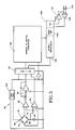
- the electrical circuit of the digital load cell 20 of Figures 1 to 4 includes strain gauges 75, 76, 79 and 80 connected in the electrical brige circuit 90.
- the bridge circuit provides an analog weight signal to a preamplifier 92.
- the weight signal from preamplifier 92 is coupled through an analog filter 94 to one input of an analog switch 96.
- the output of switch 96 is connected to the input of a multiple slope integrating analog-to-digital (A/D) converter 100.
- Nickel resistor 82 is connected in series with bridge circuit 90 and provides a signal through a preamplifier 101 to another input of analog switch 96.
- Excitation is provided to bridge circuit 90 by a power supply 103 which also provides a known reference voltage through analog switch 96 to multiple slope A/D 100.
- the output of A/D converter 100 is connected to a microprocessor 105, preferably an Intel 8344.
- Microprocessor 105 controls the operation of analog switch 96 to cause analog weight signals from bridge 90 and temperature indicating signals from nickel resistor 82 to be converted to digital form by A/D converter 100 and transmitted to microprocessor 105.
- Microprocessor 105 is provided with memory 105a including ROM, EEPROM and RAM for storage of programs and of data received from A/D converter 100 and from a remote controller or computer. Microprocessor 105 is also equipped with a serial interface unit 105b connected through a driver 107 and a receiver 108 to a bus or the like for communication with a controller or computer.
- memory 105a including ROM, EEPROM and RAM for storage of programs and of data received from A/D converter 100 and from a remote controller or computer.
- Microprocessor 105 is also equipped with a serial interface unit 105b connected through a driver 107 and a receiver 108 to a bus or the like for communication with a controller or computer.
- the system includes eight digital load cells 20 as described above supporting a platform 125 suitable for holding a vehicle such as a truck.
- the load cells 20 are connected together through a junction box 127 and through a bus 128 to a master controller 130.
- the master controller may be connected to one or more peripheral devices 132 such as a printer or host computer.
- the digital load cells 20 and master controller 130 are arranged and programmed to constitute a LAN (local area network) with master controller 130 performing as the master and the load cells 20 as slaves.
- the LAN preferably utilizes the Intel BITBUS communication system.
- master controller 130 includes a microprocessor 140, preferably an Intel 8344, provided with internal RAM memory 140a and a serial interface unit 140b.
- Microprocessor 140 is connected to bus 128 for communication with the digital load cells 20 through driver 142 and receiver 143 connected to serial interface unit 140b.
- Microprocessor 140 also communicates with an address/data bus 150 to which is connected a program memory 152, RAM 153, real time clock 154 and a pair of dual transmitters 156, 157.
- Transmitters 156 and 157 connect bus 150 to various peripheral devices such as a printer 160, host computer 161, bar code encoder 163 and a serial input/output line 164.
- a parallel input/output line 166 is also connected to bus 150 through a latch 167.
- Microprocessor 140 provides weight data to a seven digit vacuum fluorescent display 172 through a display control 174.
- a keyboard 180 is connected to microprocessor 140 through a keyboard drive 182 for manual selection and inputting of various modes and options during calibration and set up of the system and for making slight changes in operation of the system.
- a non-volatile programmable memory 183 is also connected to microprocessor 140 for the storage of various calibration constants and similar information determined during calibration and set up of the system.
- the master controller shown in Figure 8 is manufactured and sold by Toledo Scale Corporation, applicant of the present application, as a Model 8530 Digital Indicator.
- the master controller acting as a LAN master, polls the load cells, LAN satellites or slaves, at a desired rate to receive weight data from each load cell.
- the data from each load cell may be operated on in certain respects, summed with the data from other load cells of the scale and the result further operated on to produce the final displayed weight.
- each load cell or group of load cells sharing an A/D converter, could be connected individually to the master controller rather than through a common bus.
- the essential feature is that the master controller receive and operate on digital information from each of the multiple load cells.
- the digital load cells illustrated in Figures 1 to 5 are programmed to operate as slaves to a master controller or host computer and to respond to commands directed to it.
- the load cell may act alone with a controller or as one load cell in a multiple load cell scale or system with a common or master controller.
- Each load cell has a unique address stored in memory which, in the latter case, allows the master controller to send commands to it only. All load cells are provided during manufacture with the same address which, if necessary, is replaced with a unique address during set up of the scale.
- the digital load cell is also programmed to compensate its weight readings for temperature effects on zero and span, for span trim and for linearity and creep.
- the compensation algorithms employed including the values of the constants are stored in the load cell memory.
- the values of the constants are determined during manufacture of the load cell.
- the constants are determined by connecting the load cell to a host computer during manufacture, subjecting the load cell to the varying weights and temperature conditions required to provide data for use in the corrective algorithms and using the data to solve for the respective constants.
- the constants are then transmitted by the host computer to the load cell and stored in memory.
- W C D ⁇ W R (1 + W R ⁇ E) (1)
- W C is the weight corrected for linearity
- W R is the uncorrected weight reading
- D and E are constants.
- the values of the constants are determined by taking weight readings at half load and full load and inserting the values into the equation. If and are the values at half load and and are the values at full load and is set equal to then and The values of the constants D and E in these equations are then transmitted to the load cell for use in linearity corrections during operation.
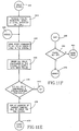
- FIG. 9A to 9M illustrates the operation of the digital load cell, whether connected in a single or multiple load cell system and in calibration or normal operation.
- operation is begun in the "silent" mode at block 251. This is essentially a local mode in that the controller or host computer has not yet initiated communication with the load cell.
- the load cell address is taken from memory and checked for validity. If the stored address was invalid an address of arbitrary value, for example, 1 or 240, is loaded at block 255. After the stored address has been determined to be valid or a new one assigned, operation proceeds directly or through point 254 to block 257 where a check is made for ROM errors and a flag is set if any such errors are found.
- a temperature reading is obtained from nickel resistor 82 in Figure 5 and stored for compensation use.
- a digital weight reading is taken and a negative out-of-range flag cleared.
- the weight reading is checked at block 262 to determine whether or not it is out of range. If not, operation proceeds through point 264 to block 268 ( Figure 9B) where a determination is made as to whether the data should be compensated or presented in its raw form. If, at block 262, the weight reading is determined to be out-of-range a flag is set at block 269 and operation proceeds through point 270 to block 272 ( Figure 9B) . Likewise, if the weight reading is not to be compensated as determined at block 268 operation jumps through points 270 to block 272.
- a subroutine is performed at block 275 to temperature compensate the zero and span coefficients.
- a subroutine "LINCOR" is utilized to correct the weight reading for nonlinearity as will be described below.
- Subroutines are performed at blocks 277 and 278, respectively, to modify the weight reading according to a span trim coefficient and to correct the weight reading for creep in the load cell.
- operation proceeds through point 319 to a series of inquiries to determine whether or not the message is one containing compensation data, such as algorithm compensation constants, to be stored in memory.
- compensation data such as algorithm compensation constants
- a determination is made as to whether or not the message includes temperature compensation data. If not, operation proceeds through point 323 to, in sequence, block 326 ( Figure 9H) to determine if the data is creep compensation data, point 327 and block 329 ( Figure 9J) to determine if the data is linearity compensation data, and point 330 and block 331 ( Figure 9K) to determine if the data is span trim calibration data.
- operation proceeds through point 333 to block 335 ( Figure 9G) where the data is stored in memory. A check is then made at block 336 to determine if the data load was successful. If so, operation proceeds through point 310 to block 311 to respond that the message command has been implemented and then through point 296 to block 295. If the data load was not successful, a response to that effect is sent at block 338 and operation proceeds through point 296 to block 295.
- Figures 10A and 10B illustrate the steps in subroutine LINCOR performed at block 276 ( Figure 9B) for providing a linearity correction to the weight reading.
- the subroutine is entered at point 350 ( Figure 10A) and proceeds to block 351 where the linearity compensation constants D and E are loaded. Operation then proceeds to block 353 where a check is made to determine if the constants were loaded correctly. If not, operation proceeds through point 354 to block 355 ( Figure 10B) where an error flag is set and operation returns through point 357 to the main program at block 277. If the linearity compensation constants were loaded satisfactorily as determined at block 353, operation proceeds to block 358 where a linearity-corrected weight reading is calculated and stored. Operation then returns through point 357 to block 277 in the main program.
- the flow chart of Figures 11A to 11L illustrates the operation of the master controller 130 in the scale of Figures 6 and 7.
- the number of load cells in the system is extracted from memory at block 403 and the information checked at block 405. If the number of load cells has not been entered and the cells identified set up mode will be selected at block 406 and operation will jump through point 407 to decision block 410 ( Figure 11B) to check for keyboard activity. If there is keyboard activity and the system is in set up mode as determined at block 412 operation jumps through point 413 to decision block 415 ( Figure 11C) to determine if the number of load cells and their addresses are known.
- operation proceeds to decision point 417 to determine if the keyboard indicates single/total key activity. If so, operation jumps through point 418 to blocks 420 and 421 ( Figure 11D) where an appropriate display is ordered and a single cell flag set or cleared according to whether one or more load cells are in the system. Operation then jumps back through point 423 to blocks 425 and 426 ( Figure 11C) where the number of load cells is entered and addresses assigned to them.
- the load cell addresses are assigned by connecting only the first load cell to the bus, addressing it as number 240 which is assigned to all load cells at manufacture and then instructing it to change that address to the newly assigned address.
- the second load cell in the system is then connected to the bus and the procedure repeated. This continues until all load cells have been connected to the bus and assigned addresses.
- operation proceeds through point 430 to blocks 432 and 433 ( Figure 11E) where a reset command is sent to all load cells followed by an order to supply data when polled. If any cell does not respond positively as determined at block 435 the address of the highest ranking non-responsive cell is displayed at block 436 to enable operator intervention, if necessary. Operation then jumps through point 423 to blocks 425 and 426 ( Figure 11C) where load cell addresses are again assigned and then returns through point 430 to blocks 432, 433 and 435. Operation proceeds around this loop until all load cells in the system have responded positively as determined at decision block 435.
- operation proceeds through point 440 to decision block 442 ( Figure 11F) to determine if the system has exited set up mode. If not operation jumps through point 445 to block 446 ( Figure 11G) to begin checking for the activation of one or more of a series of keys which command various set up functions. If a key command is detected at decision block 446 to reassign a load cell address, operation jumps through point 448 to the procedure illustrated in Figures 12A and 12B which will be described below. Reassignment of a load cell address may become necessary when, for example, a single load cell in the system of Figures 6 and 7 has been determined to be defective and must be replaced. In that case, a new load cell must be assigned the same address as that of the load cell replaced.
- operation proceeds through point 430 to blocks 432 and 433 ( Figure 11E) where the load cells are reset and reordered to supply data. If all cells do not respond positively as determined at block 435, operation proceeds through block 436 and point 423 to blocks 425 and 426 ( Figure 11C) to again assign load cell addresses and then returns through point 430 until, as determined at block 435 ( Figure 11E), all cells respond positively. Operation then proceeds through point 440 and decision block 442 ( Figure 11F) and through point 470 and block 472 ( Figure 11H) to again read all cells at block 475.
- the single cell flag is not set operation is begun at block 500 to adjust the weight readings from the load cells for load position and to sum the readings to obtain the total weight on the scale.
- the total weight register is cleared and at block 501 a register is set to N, the number of load cells in the system.
- the load position correction constant X for the highest numbered load cell in the system is fetched from memory at block 503 and loaded into register M. If the fetching of the load position constant X for load cell N was not successful as determined at block 505, the numeral 1 is loaded into register M at block 506 and operation continues.
- Operation proceeds in the same manner as described above until the weight readings from all of the load cells have been multiplied by the respective load position correction constants and summed in the total weight register. At that point, block 514 will determine that the readings from all load cells have been summed. The zero and span calibration constants will then be fetched from memory at block 517. If the memory fetch was not successful as determined at block 519 an error display will be made at block 520 and operation will return through point 407 to block 410 ( Figure 11B). If the memory fetch was successful operation proceeds through point 522 to block 525 ( Figure 11L) where the zero and span constants are applied to the weight reading. Then, at block 527, other operations are performed relating to auto-zero and tare. At block 528 the weight reading is rounded and truncated for display and at block 530 the final weight is displayed. Operation then returns through point 407 to block 410 ( Figure 11B) to check for keyboard activity and poll the load cells for weight readings.
- An important advantage of the present invention is the ability to replace one or more defective load cells in a multiple load cell scale. Since each load cell in a scale can be monitored and diagnosed individually a defective load cell can be easily found. When that happens, a new load cell is inserted into the system to replace the defective one and an address is assigned to the new load cell.
- Figures 12A and 12B illustrate the procedure for assigning the address to the new load cell.
- the procedure is entered through point 448 when a key command to reassign a load cell address has been detected at block 446 ( Figure 11G).
- the new load cell address which in this case would be the same as that of the removed defective load cell, is entered through the keyboard at block 575 in response to a prompting message from the display.
- an address of 240 is loaded into an address register and operation proceeds through point 579 to block 580.
- a load cell address change command and the new address are transmitted to the load cell address, in this case 240, in the address register. Then, at block 581 a determination is made as to whether or not a positive response was obtained from the addressed load cell. If so, the new address has been satisfactorily assigned and operation returns through point 445 to scanning the keyboard at block 446 ( Figure 11G). This would normally be the result when the replacement load cell is a new load cell since address 240 is loaded into all load cells at manufacture.
- the replacement load cell would not be a new load cell and could have a stored address other than 240. In that case, operation would proceed from decision block 581 to block 583 where the contents of the address register are decremented and then, at block 585, compared to zero. If the contents of the address register are not equal to zero operation returns through point 579 to transmit the address change command and new address to the decremented load cell address and then check at block 581 for a positive response. Operation proceeds in this manner until a positive response is obtained from the replacement load cell or until the contents of the address register have been determined to be equal to zero at block 585. In that case the display is caused at block 587 to indicate that no functioning load cell is attached to the system and operation returns through point 440 to block 442 ( Figure 11F).
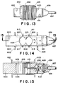
- Figures 13-15 and Figures 16 and 17 illustrate additional examples of modular digital load cells embodying this invention.
- a double guided beam counterforce 600 and two enclosure rings 602, 603 are cast in stainless steel.
- An upper beam 605 and a lower beam 606 are defined by a plurality of holes drilled through the stainless steel block to form the opening 608.
- a pair of strain gages 610, 611 are mounted on the upper beam 605 aligned along its center line in the conventional manner.
- a nickel resistor 615 is positioned between the gages and used for temperature sensing.
- Another pair of strain gages 617, 618 is mounted in the same fashion on lower beam 606. Pairs of tapped holes at 620, 621 are provided for mounting the counterforce to a load receiver at one end and a base at the other end.
- printed circuit boards 625, 626 are mounted on the sides of counterforce 600 and another circuit board 628 is mounted within a cavity 630 formed in one end of the counterforce.
- the circuit boards contain the analog and digital circuits required to make the load cell perform in a manner similar to the load cell of Figures 1 to 4.
- Suitable wiring is provided among the circuit boards and strain gages and to a connector 633 at the open end of cavity 630.
- a glass and metal seal 635 is soldered to counterforce 600 to close the open end of cavity 630.
- Seal 635 carries wiring terminals for mating with the wiring of connector 633. Wiring from the terminals of seal 635 is routed to a cable 637. Seal 635, the wiring and the end of cable 637 are enclosed by an epoxy seal 639.
- Printed circuit boards 625 and 626 along with the strain gage bearing portions of the dual beam counterforce 600 are enclosed and sealed by means of a tubular bellows 642.
- Bellows 642 is fitted over one end of counterforce 600 and positioned between rings 602 and 603.
- Bellows 642 is attached to rings 602 and 603 by welding the outer periphery of each ring to the inner periphery of the ends 650, 651 of the bellows 642.
- the basic load cell shown in Figures 16 and 17 is known as a torsion ring load cell.
- the counterforce generally indicated as 675 is formed of stainless steel and includes an outer ring 677 and a central hub 679 connected by an inner tapered diaphragm 680 and an outer tapered diaphragm 681 to a torsion ring 684.
- the outer rim is usually held stationary by bolts or the like and the load or force applied to hub 679. This loading produces circumferentially directed compressive strain on the upper portion of the torsion ring 684 and circumferentially directed tensile strain on the lower portion of the torsion ring.
- strain gages 687-690 are spaced at 90° intervals on the upper surface of torsion ring 684 with their strain sensing elements oriented circumferentially to sense compressive strains produced in the ring.
- strain gages only two being shown and identified as 692 and 693, are mounted on the lower surface of torsion ring 684 directly below the compression gages to sense tensile strains in the torsion ring.
- the strain gages are preferably connected in an electrical bridge circuit.
- Two holes 694a, 694b are provided through outer diaphragm 681 for passage of wiring from strain gages 687-690 to the cavity below torsion ring 684.
- a loading hole 695 is provided in hub 679 to facilitate the application of loads to the load cell.
- an annular circuit board 700 is fitted over the lower portion of hub 679 and secured thereto by glue or other suitable attaching means.
- Circuit board 700 contains the analog and digital electronic circuits required to make the load cell perform in a manner similar to the load cell of Figures 1-4.
- a cable nipple 701 is provided through an opening in outer rim 677 for transmission of information between the digital load cell and a controller or computer.
- the cavities above and below torsion ring 684 are closed and sealed by means of annular metal seals 704 and 705, such as stainless steel foil, welded or otherwise suitably attached to the inner periphery of outer rim 677 and the outer periphery of hub 679. If desired, the cavities above and below torsion ring 684 may be filled with an inert gas.
- the load cell is another modular, self-contained digital load cell which can and must be characterized and controlled only through cable nipple 701.
Landscapes
- Physics & Mathematics (AREA)
- General Physics & Mathematics (AREA)
- Measurement Of Force In General (AREA)
- Investigating Strength Of Materials By Application Of Mechanical Stress (AREA)
- Gas Exhaust Devices For Batteries (AREA)
- Testing Of Balance (AREA)
Claims (17)
- Appareil de pesage comprenant au moins un appui de réaction (12, 600, 675), un moyen transducteur (75, 76, 79, 80, 610, 611, 617, 618, 687, 688, 689, 690) monté sur ledit appui de réaction, un moyen de circuit (14, 625, 626, 630, 700) comprenant un moyen (100) pour produire des représentations numériques de charges appliquées audit appui de réaction, un moyen (105) pour appliquer au moins un facteur de correction auxdites représentations numériques, et un moyen (105, 105b, 107, 108) pour transmettre lesdites représentations numériques, ledit moyen de circuit (14, 625, 626, 630, 700) étant sensible à une commande externe, et un moyen (15, 642, 704) étant prévu pour former une enceinte étanche pour ledit moyen transducteur et ledit moyen de circuit.
- Appareil de pesage selon la revendication 1, caractérisé en ce que ledit moyen formant enceinte (15) comprend un moyen (33) réalisant un chemin à travers ledit moyen formant enceinte pour une communication externe avec ledit moyen de circuit.
- Appareil de pesage selon la revendication 1, ou 2, caractérisé en ce que ledit moyen de circuit (14, 625, 626, 630, 700) est fixé audit appui de réaction.
- Appareil de pesage selon la revendication 1, 2, ou 3, caractérisé en ce que ledit appui de réaction (12) est une tige à bascule et en ce que ledit facteur de correction corrige la non-linéarité desdites représentations numériques avec des charges variables sur ladite tige à bascule.
- Appareil de pesage selon la revendication 1, caractérisé en ce que ledit appui de réaction (600) est un appui de réaction à bras à double guidage.
- Appareil de pesage selon la revendication 1, caractérisé en ce que ledit appui de réaction (675) est un appui de réaction à anneau de torsion.
- Appareil de pesage selon l'une quelconque des revendications précédentes, caractérisé en ce que ledit moyen de circuit (14, 625, 626, 630, 700) comprend un moyen (82, 615, 101, 100) pour produire des représentations numériques de la température dudit appui de réaction, un moyen (105a) pour mémoriser un facteur de correction de température, et un moyen (105) pour utiliser lesdites représentations de température et ledit facteur de correction de température pour corriger lesdites représentations numériques de charge.
- Appareil de pesage selon l'une quelconque des revendications précédentes, caractérisé en ce qu'au moins un capteur de charge (20) comprend une colonne monobloc (12) ayant une surface d'appui incurvée (60, 65) à chaque extrémité, le rayon de courbure de chaque surface d'appui étant plus grand que la moitié de la hauteur de la colonne.
- Appareil de pesage selon la revendication 8, caractérisé en ce que ledit moyen transducteur (75, 76, 79, 80) comprend une première paire de jauges de contrainte (75, 76) pour détecter la contrainte de compression produite par lesdites charges et une seconde paire (79, 80) de jauges de contrainte pour détecter la contrainte de traction produite par lesdites charges, et un moyen de raccordement desdites jauges de contrainte en un circuit électrique en pont (90).
- Appareil de pesage selon la revendication 8, caractérisé en ce qu'il comprend un moyen (100) associé avec ladite colonne (12) pour fournir des représentations numériques d'une charge sur lesdites surfaces d'appui (60, 65), un moyen (105a) pour mémoriser une expression mathématique pour la correction de linéarité de la sortie dudit moyen transducteur, et un moyen (105) pour combiner lesdites représentations numériques avec ladite expression mathématique pour fournir des représentations numériques corrigées.
- Appareil de pesage selon l'une quelconque des revendications 1 à 9, caractérisé en ce que ledit appui de réaction est un appui de réaction à tige à bascule (12), et en ce qu'il comprend de plus un moyen (105a) pour mémoriser une expression mathématique pour la correction de linéarité de la sortie dudit appui de réaction, et un moyen (105) pour combiner lesdites représentations numériques avec ladite expression mathématique pour fournir des représentations numériques corrigées.
- Appareil de pesage selon la revendication 11, caractérisé en ce qu'il comprend un moyen de montage de circuit (17), fixé audit appui de réaction, pour monter ledit moyen de représentation numérique, ledit moyen de mémorisation, et ledit moyen de combinaison.
- Appareil de pesage selon la revendication 1, caractérisé par une pluralité de capteurs de charge (20), chaque capteur de charge (20) comprenant ledit appui de réaction (12), ledit moyen transducteur (75, 76, 79, 80), ledit moyen de circuit (14), ledit moyen formant enceinte (15, 642, 704), ledit moyen de chemin (33, 637, 701), et par un moyen de réception de charge (125) supporté par lesdits capteurs de charges, un moyen (127, 128) reliant lesdits capteurs de charge en un réseau local, un moyen (130) pour interroger lesdits capteurs de charge pour recevoir lesdites représentations numériques, et un moyen (132) pour combiner lesdites représentations numériques du poids total sur ledit moyen de réception de charge.
- Appareil de pesage selon la revendication 13, caractérisé en ce que les appuis de réaction sont des tiges à bascule (12).
- Appareil de pesage selon la revendication 13 ou 14, caractérisé en ce que ledit moyen de circuit (14) comprend un moyen (105, 150a) pour appliquer au moins un facteur de correction auxdites représentations numériques.
- Appareil de pesage selon l'une quelconque des revendications précédentes, caractérisé en ce que ledit moyen de circuit (14) comprend un moyen (105a) pour mémoriser lesdites représentations numériques, et un moyen (105b) sensible à des instructions externes pour transmettre les représentations numériques mémorisées.
- Appareil de pesage selon l'une quelconque des revendications précédentes, caractérisé en ce que ledit moyen de circuit (14) du, ou de chaque, capteur de charge comprend un moyen (105a) sensible à des instructions externes pour mémoriser une adresse affectée de manière externe pour le capteur de charge.
Applications Claiming Priority (2)
| Application Number | Priority Date | Filing Date | Title |
|---|---|---|---|
| US126272 | 1987-11-30 | ||
| US07/126,272 US4815547A (en) | 1987-11-30 | 1987-11-30 | Load cell |
Publications (3)
| Publication Number | Publication Date |
|---|---|
| EP0319176A2 EP0319176A2 (fr) | 1989-06-07 |
| EP0319176A3 EP0319176A3 (fr) | 1991-03-13 |
| EP0319176B1 true EP0319176B1 (fr) | 1993-03-31 |
Family
ID=22423934
Family Applications (1)
| Application Number | Title | Priority Date | Filing Date |
|---|---|---|---|
| EP88310890A Revoked EP0319176B1 (fr) | 1987-11-30 | 1988-11-18 | Dispositif de pesage avec capteur de force digital et enclos étanche |
Country Status (10)
| Country | Link |
|---|---|
| US (1) | US4815547A (fr) |
| EP (1) | EP0319176B1 (fr) |
| JP (1) | JP2709837B2 (fr) |
| CN (1) | CN1016640B (fr) |
| AR (1) | AR245820A1 (fr) |
| AU (1) | AU599884B2 (fr) |
| BR (1) | BR8806267A (fr) |
| CA (1) | CA1304761C (fr) |
| DE (1) | DE3879892T2 (fr) |
| MX (1) | MX165666B (fr) |
Cited By (9)
| Publication number | Priority date | Publication date | Assignee | Title |
|---|---|---|---|---|
| EP0319202A2 (fr) * | 1987-11-30 | 1989-06-07 | Mettler-Toledo, Inc. | Balance compensée avec multiples capteurs de charge |
| DE4417228A1 (de) * | 1994-05-17 | 1995-11-23 | Michael Dr Altwein | Dehnungsmeßstreifen-Meßanordnung, Verwendung derselben und Modulationsverstärker für derartige Meßanordnungen |
| GB2307054A (en) * | 1995-11-06 | 1997-05-14 | Lf Whaler Ltd | Automatic poultry weigher |
| EP0800064A2 (fr) * | 1996-04-01 | 1997-10-08 | Hottinger Baldwin Messtechnik Gmbh | Capteur de pesage de forme allongé |
| AU683329B2 (en) * | 1994-03-01 | 1997-11-06 | Mettler-Toledo, Inc. | Load cell with modular calibration components |
| US6216542B1 (en) | 1997-05-28 | 2001-04-17 | K-Tron Technologies Inc. | Monolithic force sensor |
| WO2003078938A2 (fr) * | 2002-03-18 | 2003-09-25 | Mettler-Toledo Gmbh | Capteur de force, dispositif de montage pour un capteur de force et balance associee |
| US6655421B2 (en) | 2001-08-29 | 2003-12-02 | Yamato Scale Company, Limited | Weight-based, multiple filler filling machine |
| RU2455556C2 (ru) * | 2004-12-24 | 2012-07-10 | Эебас ЮКей Лимитид | Шарнирно-неподвижная опора (варианты), способ ее изготовления, способ измерения нагрузок, летательный аппарат и способы модернизации и оценки эксплуатационных характеристик летательного аппарата или его составляющей части |
Families Citing this family (97)
| Publication number | Priority date | Publication date | Assignee | Title |
|---|---|---|---|---|
| US5086879A (en) * | 1989-03-24 | 1992-02-11 | Spectra-Physics, Inc. | Scale calibration/zeroing in data gathering system |
| US4909338A (en) * | 1989-06-12 | 1990-03-20 | Ncr Corporation | Method and apparatus for scale calibration and weighing |
| US4955441A (en) * | 1989-09-26 | 1990-09-11 | Toledo Scale Corporation | Load cell mounting for rotational control |
| US5131482A (en) * | 1989-12-28 | 1992-07-21 | General Electrodynamics | Self-contained weighing system and method |
| CA2038404C (fr) * | 1990-05-16 | 1995-08-22 | Neil C. Griffen | Methode et appareil de pesage a compensation d'hysteresis |
| JP2518966B2 (ja) * | 1990-11-28 | 1996-07-31 | 株式会社テック | 電子秤 |
| JPH04130047U (ja) * | 1991-03-09 | 1992-11-30 | シンポ工業株式会社 | ロードセル |
| US5442146A (en) | 1992-04-03 | 1995-08-15 | Weigh-Tronix, Inc. | Counting scale and load cell assembly therefor |
| DE4344565C1 (de) * | 1993-12-24 | 1995-03-23 | Schenck Ag Carl | Vorrichtung zum Messen von Lasten |
| DE4402655C1 (de) * | 1994-01-29 | 1995-04-20 | Sartorius Gmbh | Elektrische Waage mit Korrektur des Feuchteeinflusses |
| FR2719408B1 (fr) * | 1994-04-29 | 1998-05-07 | Fmc Corp | Transducteur de force à sortie numérique pour dispositif d'équilibrage de roue. |
| US5910645A (en) * | 1994-05-11 | 1999-06-08 | Hottinger Baldwin Messtechnik Gmbh | Method and apparatus for making load cells less sensitive to off-center load applications |
| DE4416442A1 (de) * | 1994-05-11 | 1995-11-16 | Hottinger Messtechnik Baldwin | Verfahren und Vorrichtung zum Abgleich eines Meßkörpers eines Meßwertaufnehmers |
| DE69500919T2 (de) * | 1994-11-29 | 1998-06-10 | M & M Electric Service Co Inc | Festkörper-Faserbandsensor |
| DE9419696U1 (de) * | 1994-12-13 | 1995-02-02 | Hottinger Messtechnik Baldwin | Wägezellenanordnung |
| US5629489A (en) * | 1995-02-06 | 1997-05-13 | Weigh-Tronix, Inc. | Load cell assembly with linearization and common mode discrimination of complementary force-responsive signals |
| US5837946A (en) * | 1995-06-16 | 1998-11-17 | Weigh-Tronix, Inc. | Force sensitive scale and dual load sensor cell for use therewith |
| US5606516A (en) * | 1995-08-07 | 1997-02-25 | Fairbanks Scales Inc. | Digitally compensated hydraulic scale system |
| US5780783A (en) * | 1995-09-19 | 1998-07-14 | Heider; Leon J. | Vehicle load weighing system |
| US5841077A (en) * | 1995-12-01 | 1998-11-24 | Kolaci; Rudolph J. | Digital load cell assembly |
| US5814771A (en) * | 1996-02-16 | 1998-09-29 | Structural Instrumentation, Inc. | On-board microprocessor controlled load weighing system |
| US5837945A (en) * | 1996-04-24 | 1998-11-17 | Hardy Instruments, Inc. | Refuse weighing system and method |
| JP3681249B2 (ja) * | 1996-08-23 | 2005-08-10 | 大和製衡株式会社 | 計量及び包装システム |
| JP3681248B2 (ja) * | 1996-08-23 | 2005-08-10 | 大和製衡株式会社 | 計量システム |
| CA2186094A1 (fr) * | 1996-09-20 | 1998-03-21 | Walter Kostiuk | Systeme de pesage dynamique |
| US5805466A (en) * | 1996-11-27 | 1998-09-08 | Motorola Inc. | Device and method for calibrating a signal |
| DE10005445C2 (de) | 1999-02-08 | 2002-08-14 | Takata Corp | Diagnoseverfahren für eine Sitzlastmessvorrichtung |
| US6459050B1 (en) * | 1999-09-20 | 2002-10-01 | Ut-Battelle, Inc. | Method and appartus for converting static in-ground vehicle scales into weigh-in-motion systems |
| US6639156B2 (en) * | 1999-12-30 | 2003-10-28 | Tom J. Luke | Method and device for monitoring inventory |
| JP2001330507A (ja) * | 2000-05-23 | 2001-11-30 | Yazaki Corp | センサユニット、及びセンサユニット調整システム |
| DE10041251B4 (de) * | 2000-08-23 | 2010-03-11 | HBM Wägetechnik GmbH | Eichfähiges Wägesystem und Verfahren zur Ermittlung eichpflichtiger Meßwertdaten |
| US6566613B1 (en) | 2000-11-03 | 2003-05-20 | Enzo Gesuita | Control system for multihead weigher |
| JP4743959B2 (ja) * | 2000-12-26 | 2011-08-10 | 大和製衡株式会社 | ロードセル |
| JP4766771B2 (ja) * | 2001-04-26 | 2011-09-07 | 大和製衡株式会社 | ロードセル |
| US6822172B2 (en) * | 2001-05-23 | 2004-11-23 | Mettler-Toledo, Inc. | Combined vehicle scale through the use of lateral connections |
| US6552278B2 (en) * | 2001-09-10 | 2003-04-22 | Weigh-Tronix Inc. | Multiple load sensing multi-load cell scale and method |
| US6919516B2 (en) * | 2002-01-08 | 2005-07-19 | Mettler-Toledo | RF multiple load cell scale |
| EP1347278B1 (fr) * | 2002-03-18 | 2005-08-03 | Mettler-Toledo GmbH | Transducteur de mesure de force pour une balance et balance |
| ATE301280T1 (de) * | 2002-03-18 | 2005-08-15 | Mettler Toledo Gmbh | Modulare kraftmesszelle für eine waage und waage |
| DE10221628B4 (de) * | 2002-05-15 | 2005-06-23 | Sartorius Ag | Kraftmesssystem mit mehreren Kraftmesszellen und mit einer Schaltung zur Errechnung eines Gesamtsignals |
| DE10227121C1 (de) * | 2002-06-13 | 2003-11-27 | Bizerba Gmbh & Co Kg | Verfahren zum Austausch digitaler Wägezellen |
| US20050086133A1 (en) * | 2003-01-08 | 2005-04-21 | Scherer William H. | System and method for sensing and analyzing inventory levels and consumer buying habits |
| ITMO20030134A1 (it) * | 2003-05-09 | 2004-11-10 | Cooperativa Bilanciai Cam Pogalliano A R Soc | Sistema di pesatura |
| US7009118B2 (en) * | 2003-05-13 | 2006-03-07 | Dynamic Datum Llc | Vehicle load weighing system and load cells for such systems |
| US7423225B1 (en) * | 2004-11-09 | 2008-09-09 | Intercomp Company | Weigh in motion technology |
| US20060137914A1 (en) * | 2004-12-23 | 2006-06-29 | Osmos S.A. | Method and device for measuring the weight applied to the ground by at least one axle |
| US7487066B2 (en) * | 2005-04-28 | 2009-02-03 | Caterpillar Inc. | Classifying a work machine operation |
| US7953559B2 (en) * | 2005-04-28 | 2011-05-31 | Caterpillar Inc. | Systems and methods for maintaining load histories |
| CN100567912C (zh) * | 2005-06-07 | 2009-12-09 | 株式会社岛津制作所 | 称重单元式电子秤 |
| JP4829305B2 (ja) * | 2005-10-12 | 2011-12-07 | ヴィポテック ヴィーゲ−ウント ポジティオニエルシステーメ ゲーエムベーハー | 受け固定具のついた秤量セル |
| DE102005055755B4 (de) * | 2005-11-21 | 2019-12-12 | Wipotec Wiege- Und Positioniersysteme Gmbh | Vorrichtung zum Wiegen mit mehreren Wägezellen |
| US7472599B2 (en) * | 2006-06-30 | 2009-01-06 | Caterpillar Inc. | Strain sensing device |
| US7908928B2 (en) * | 2006-10-31 | 2011-03-22 | Caterpillar Inc. | Monitoring system |
| AU2008255547A1 (en) * | 2007-05-28 | 2008-12-04 | Loadsense Technologies Corporation | A portable modular scale system |
| CA2689921A1 (fr) * | 2007-05-29 | 2008-12-04 | Loadsense Technologies Corporation | Palette avec balance |
| CN101680801B (zh) * | 2007-06-07 | 2013-09-25 | 梅特勒-托利多公开股份有限公司 | 多重测力装置、测力模块以及用于状态监测的方法 |
| MX2009012522A (es) * | 2007-06-07 | 2009-12-09 | Mettler Toledo Ag | Metodo para monitorear la condicion de un dispositivo de medicion de fuerza, dispositivo de medicion de fuerza y modulo de medicion de fuerza. |
| US8597505B2 (en) | 2007-09-13 | 2013-12-03 | Fresenius Medical Care Holdings, Inc. | Portable dialysis machine |
| US8105487B2 (en) | 2007-09-25 | 2012-01-31 | Fresenius Medical Care Holdings, Inc. | Manifolds for use in conducting dialysis |
| US8240636B2 (en) | 2009-01-12 | 2012-08-14 | Fresenius Medical Care Holdings, Inc. | Valve system |
| US9199022B2 (en) | 2008-09-12 | 2015-12-01 | Fresenius Medical Care Holdings, Inc. | Modular reservoir assembly for a hemodialysis and hemofiltration system |
| US9308307B2 (en) | 2007-09-13 | 2016-04-12 | Fresenius Medical Care Holdings, Inc. | Manifold diaphragms |
| US9358331B2 (en) | 2007-09-13 | 2016-06-07 | Fresenius Medical Care Holdings, Inc. | Portable dialysis machine with improved reservoir heating system |
| CA2960103C (fr) | 2007-11-29 | 2020-03-10 | Fredenius Medical Care Holdings, Inc. | Systeme et procede pour realiser une hemodialyse et une hemofiltration |
| GB0806918D0 (en) * | 2008-04-16 | 2008-05-21 | Airbus Uk Ltd | Method and apparatus for monitoring a structure |
| EP2120023B1 (fr) * | 2008-05-15 | 2012-04-18 | Mettler-Toledo AG | Cellule de pesage encapsulée dotée d'un réglage de la charge angulaire |
| MX343532B (es) | 2008-10-07 | 2016-11-09 | Fresenius Medical Care Holdings Inc | Sistema de cebado y metodo para sistemas de dialisis. |
| CA2928208A1 (fr) | 2008-10-30 | 2010-06-03 | Fresenius Medical Care Holdings, Inc. | Systeme de dialyse portatif modulaire |
| JP5233622B2 (ja) * | 2008-12-02 | 2013-07-10 | アイシン精機株式会社 | 車両シート用乗員荷重センサ |
| DE102008064169B4 (de) * | 2008-12-22 | 2013-07-18 | Hottinger Baldwin Messtechnik Gmbh | Wägezelle |
| US8191434B2 (en) | 2009-04-03 | 2012-06-05 | Mettler-Toledo, LLC | Device and method for temperature compensation testing of digital load cells |
| IT1395823B1 (it) * | 2009-05-27 | 2012-10-26 | Ecomembrane Srl | Misuratore di livello di riempimento per gasometri a membrana |
| US8237066B2 (en) | 2009-12-30 | 2012-08-07 | Mettler-Toledo, LLC | Weighing apparatus employing load cells of different capacity |
| DE102010014152B4 (de) | 2010-04-07 | 2015-12-24 | Hottinger Baldwin Messtechnik Gmbh | Wägezelle |
| FR2971843B1 (fr) * | 2011-02-21 | 2013-09-06 | Precia | Capteur de contraintes pour installation de pesage electronique |
| JP5730650B2 (ja) * | 2011-04-14 | 2015-06-10 | 大和製衡株式会社 | コンベヤスケール用ロードセル |
| CN103674212B (zh) | 2012-09-19 | 2017-11-28 | 梅特勒-托利多有限公司 | 测力计称重模块 |
| ES2719124T3 (es) * | 2012-12-20 | 2019-07-08 | Hoffmann La Roche | Sistema de gestión de líquidos y/o sólidos a granel |
| US9201036B2 (en) | 2012-12-21 | 2015-12-01 | Fresenius Medical Care Holdings, Inc. | Method and system of monitoring electrolyte levels and composition using capacitance or induction |
| US9157786B2 (en) | 2012-12-24 | 2015-10-13 | Fresenius Medical Care Holdings, Inc. | Load suspension and weighing system for a dialysis machine reservoir |
| DK2954333T3 (da) * | 2013-02-07 | 2017-03-20 | Kistler Holding Ag | Method for producing an acceleration sensor |
| US9713559B2 (en) | 2013-03-15 | 2017-07-25 | Stryker Corporation | Medical support apparatus |
| US20140263389A1 (en) * | 2013-03-15 | 2014-09-18 | David Michael Perozek | Apparatus and methods for a semi-automatic pill counting tray |
| US9354640B2 (en) | 2013-11-11 | 2016-05-31 | Fresenius Medical Care Holdings, Inc. | Smart actuator for valve |
| DE202015002361U1 (de) * | 2014-06-16 | 2015-06-17 | Francotyp-Postalia Gmbh | Verbesserungen an einer dynamischen Waage mit mehreren Wägeschalen |
| CN104154984A (zh) * | 2014-08-22 | 2014-11-19 | 济南金钟电子衡器股份有限公司 | 一种应用于液压翻板汽车衡的新型称重指示器 |
| US10330522B2 (en) | 2015-12-17 | 2019-06-25 | Stryker Corporation | Person support apparatus with exit detection system and/or scale system |
| US10527509B2 (en) | 2016-09-29 | 2020-01-07 | FUTEK Advanced Sensor Technology | Hermetically sealed sensor |
| US10898400B2 (en) * | 2016-12-01 | 2021-01-26 | Stryker Corporation | Person support apparatuses with load cells |
| ES2620954B2 (es) * | 2016-12-23 | 2018-04-18 | Universidad De Alicante | Bancada inteligente para ambulancias |
| US10830025B2 (en) * | 2017-11-09 | 2020-11-10 | Baker Hughes, A Ge Company, Llc | Ultrasonic weld between components of an electrical submersible pump assembly |
| US20190162579A1 (en) * | 2017-11-29 | 2019-05-30 | Agalmic Inc. | Modular weight scale system |
| US11491062B2 (en) | 2019-04-18 | 2022-11-08 | Stryker Corporation | Patient handling apparatus with load sensor |
| US11067432B2 (en) * | 2019-05-24 | 2021-07-20 | Mettler-Toledo, LLC | Weighing instrument using a general-purpose computer as the primary display and data entry |
| US11709091B2 (en) * | 2020-04-24 | 2023-07-25 | Truthio, LLC | Remote monitoring of vehicle scale for failure prediction |
| US20220002107A1 (en) * | 2020-07-01 | 2022-01-06 | CSG Holding, Inc. | Webtension transducer load cell with integrated data interface |
| DE102021002729B3 (de) | 2021-05-26 | 2022-04-21 | Hottinger Brüel & Kjaer GmbH | Präzisions-Pendellaststütze |
Citations (1)
| Publication number | Priority date | Publication date | Assignee | Title |
|---|---|---|---|---|
| EP0171237A2 (fr) * | 1984-08-06 | 1986-02-12 | Mettler-Toledo, Inc. | Balance avec compensation d'erreurs |
Family Cites Families (18)
| Publication number | Priority date | Publication date | Assignee | Title |
|---|---|---|---|---|
| US3621927A (en) * | 1970-04-27 | 1971-11-23 | Ormond Alfred N | Unitary load cell |
| US3891870A (en) * | 1971-11-23 | 1975-06-24 | James Patrick Corbett | Rotating piezoelectric transducer mounting |
| JPS5331955Y2 (fr) * | 1972-04-13 | 1978-08-08 | ||
| GB1462808A (en) * | 1974-08-14 | 1977-01-26 | Avery Ltd W T | Processing of weight information |
| US4044920A (en) * | 1976-02-02 | 1977-08-30 | Chore-Time Equipment, Inc. | Load cell and control for bulk bin |
| JPS5817238Y2 (ja) * | 1977-05-16 | 1983-04-07 | 東芝テック株式会社 | ロ−ドセルの防水装置 |
| US4248317A (en) * | 1979-09-10 | 1981-02-03 | Cardinal Scale Manufacturing Company | Load cell apparatus |
| JPS56164932A (en) * | 1980-05-23 | 1981-12-18 | Toyo Baldwin:Kk | System for prevention of error of shearing type measuring beam supported at both ends |
| FR2505496A1 (fr) * | 1981-05-11 | 1982-11-12 | Toux Jacques | Dispositif capteur de force pour appareil de mesure et appareil de mesure, notamment appareil de pesage, equipe d'un tel dispositif |
| EP0106900B1 (fr) * | 1982-09-24 | 1985-12-18 | Carl Schenck Ag | Transducteur de mesure de force |
| JPS6122247U (ja) * | 1984-07-16 | 1986-02-08 | 花王株式会社 | 鋳型用心金 |
| JPS61201127A (ja) * | 1985-03-04 | 1986-09-05 | Hitachi Ltd | エンジン制御装置 |
| GB8507261D0 (en) * | 1985-03-20 | 1985-04-24 | Avery Ltd W & T | Load cells |
| US4609062A (en) * | 1985-07-19 | 1986-09-02 | Colt Industries Operating Corp. | Heavy-duty industrial weighing scale |
| US4703216A (en) * | 1985-09-12 | 1987-10-27 | Corbett James P | Oscillating crystal transducer systems |
| US4738324A (en) * | 1987-02-24 | 1988-04-19 | Borchard John S | Self-adjusting weighing system |
| US4799558A (en) * | 1987-06-12 | 1989-01-24 | Toledo Scale Corporation | Digital load shift compensation |
| US4804052A (en) * | 1987-11-30 | 1989-02-14 | Toledo Scale Corporation | Compensated multiple load cell scale |
-
1987
- 1987-11-30 US US07/126,272 patent/US4815547A/en not_active Expired - Lifetime
-
1988
- 1988-10-20 CA CA000580813A patent/CA1304761C/fr not_active Expired - Lifetime
- 1988-11-09 MX MX013729A patent/MX165666B/es unknown
- 1988-11-16 AU AU25651/88A patent/AU599884B2/en not_active Expired
- 1988-11-18 DE DE88310890T patent/DE3879892T2/de not_active Revoked
- 1988-11-18 EP EP88310890A patent/EP0319176B1/fr not_active Revoked
- 1988-11-22 AR AR88312524A patent/AR245820A1/es active
- 1988-11-28 JP JP63298432A patent/JP2709837B2/ja not_active Expired - Lifetime
- 1988-11-29 BR BR888806267A patent/BR8806267A/pt not_active IP Right Cessation
- 1988-11-30 CN CN88108281A patent/CN1016640B/zh not_active Expired
Patent Citations (1)
| Publication number | Priority date | Publication date | Assignee | Title |
|---|---|---|---|---|
| EP0171237A2 (fr) * | 1984-08-06 | 1986-02-12 | Mettler-Toledo, Inc. | Balance avec compensation d'erreurs |
Cited By (11)
| Publication number | Priority date | Publication date | Assignee | Title |
|---|---|---|---|---|
| EP0319202A2 (fr) * | 1987-11-30 | 1989-06-07 | Mettler-Toledo, Inc. | Balance compensée avec multiples capteurs de charge |
| EP0319202A3 (en) * | 1987-11-30 | 1990-11-14 | Toledo Scale Corporation | Compensated multiple load cell scale |
| AU683329B2 (en) * | 1994-03-01 | 1997-11-06 | Mettler-Toledo, Inc. | Load cell with modular calibration components |
| DE4417228A1 (de) * | 1994-05-17 | 1995-11-23 | Michael Dr Altwein | Dehnungsmeßstreifen-Meßanordnung, Verwendung derselben und Modulationsverstärker für derartige Meßanordnungen |
| US5777235A (en) * | 1994-05-17 | 1998-07-07 | Altwein; Michael | Strain gage measuring arrangement, use of same, and modulation amplifier for such measuring arrangements |
| GB2307054A (en) * | 1995-11-06 | 1997-05-14 | Lf Whaler Ltd | Automatic poultry weigher |
| EP0800064A2 (fr) * | 1996-04-01 | 1997-10-08 | Hottinger Baldwin Messtechnik Gmbh | Capteur de pesage de forme allongé |
| US6216542B1 (en) | 1997-05-28 | 2001-04-17 | K-Tron Technologies Inc. | Monolithic force sensor |
| US6655421B2 (en) | 2001-08-29 | 2003-12-02 | Yamato Scale Company, Limited | Weight-based, multiple filler filling machine |
| WO2003078938A2 (fr) * | 2002-03-18 | 2003-09-25 | Mettler-Toledo Gmbh | Capteur de force, dispositif de montage pour un capteur de force et balance associee |
| RU2455556C2 (ru) * | 2004-12-24 | 2012-07-10 | Эебас ЮКей Лимитид | Шарнирно-неподвижная опора (варианты), способ ее изготовления, способ измерения нагрузок, летательный аппарат и способы модернизации и оценки эксплуатационных характеристик летательного аппарата или его составляющей части |
Also Published As
| Publication number | Publication date |
|---|---|
| CN1016640B (zh) | 1992-05-13 |
| EP0319176A2 (fr) | 1989-06-07 |
| AU2565188A (en) | 1989-06-01 |
| CN1034428A (zh) | 1989-08-02 |
| AR245820A1 (es) | 1994-02-28 |
| EP0319176A3 (fr) | 1991-03-13 |
| JPH01250028A (ja) | 1989-10-05 |
| US4815547A (en) | 1989-03-28 |
| AU599884B2 (en) | 1990-07-26 |
| BR8806267A (pt) | 1989-08-15 |
| CA1304761C (fr) | 1992-07-07 |
| MX165666B (es) | 1992-11-27 |
| JP2709837B2 (ja) | 1998-02-04 |
| DE3879892D1 (de) | 1993-05-06 |
| DE3879892T2 (de) | 1993-10-28 |
Similar Documents
| Publication | Publication Date | Title |
|---|---|---|
| EP0319176B1 (fr) | Dispositif de pesage avec capteur de force digital et enclos étanche | |
| US5076375A (en) | Load cell | |
| US4804052A (en) | Compensated multiple load cell scale | |
| US20040026135A1 (en) | RF multiple load cell scale | |
| EP0295067B2 (fr) | Dispositif numérique pour compenser le déplacement de charge | |
| JP4990360B2 (ja) | コーナー荷重センサ付き上皿秤 | |
| US5004058A (en) | Weigh scale using multiple digital load cells | |
| US4967384A (en) | Highly accurate weighing system | |
| US5515737A (en) | Weighing apparatus | |
| US4313509A (en) | Weighing apparatus | |
| JPH01501503A (ja) | 一体のディジタル温度補償手段を備えた圧力トランスジューサ | |
| EP1623194B1 (fr) | Systeme de pesage | |
| US5644492A (en) | Method for compensation of weighing errors in an electronic scale | |
| JPS63273028A (ja) | 重量検出装置 | |
| EP1098177A2 (fr) | Dispositif automatique d'étalonnage d'une masse d'éprouve sous-multiple et multiple | |
| US5475384A (en) | Remote addressable transducer provided with automatic calibration and digital compensation | |
| CN1062036A (zh) | 一种对多测力计秤进行负荷位置补偿的方法 | |
| JPH08178737A (ja) | ロードセル式はかり | |
| CN1061282A (zh) | 测力计 | |
| JP4845793B2 (ja) | 計量装置の補正方法 | |
| Carrozza | Revamping of the automation and measurement systems of a steel mill and uncertainty evaluation | |
| JP2738102B2 (ja) | 電子天びんシステム | |
| JPS63193021A (ja) | 遠隔操作型電子天秤 | |
| JP2019032248A (ja) | マルチロードセル式台秤およびマルチロードセル式台秤の製造方法 | |
| KR19980015025A (ko) | 호퍼스케일 교정방법 및 그 장치 |
Legal Events
| Date | Code | Title | Description |
|---|---|---|---|
| PUAI | Public reference made under article 153(3) epc to a published international application that has entered the european phase |
Free format text: ORIGINAL CODE: 0009012 |
|
| AK | Designated contracting states |
Kind code of ref document: A2 Designated state(s): BE CH DE FR GB LI NL SE |
|
| PUAL | Search report despatched |
Free format text: ORIGINAL CODE: 0009013 |
|
| AK | Designated contracting states |
Kind code of ref document: A3 Designated state(s): BE CH DE FR GB LI NL SE |
|
| 17P | Request for examination filed |
Effective date: 19910705 |
|
| RAP1 | Party data changed (applicant data changed or rights of an application transferred) |
Owner name: METTLER-TOLEDO, INC. |
|
| 17Q | First examination report despatched |
Effective date: 19911114 |
|
| GRAA | (expected) grant |
Free format text: ORIGINAL CODE: 0009210 |
|
| AK | Designated contracting states |
Kind code of ref document: B1 Designated state(s): BE CH DE FR GB LI NL SE |
|
| REF | Corresponds to: |
Ref document number: 3879892 Country of ref document: DE Date of ref document: 19930506 |
|
| ET | Fr: translation filed | ||
| PLBI | Opposition filed |
Free format text: ORIGINAL CODE: 0009260 |
|
| PLBI | Opposition filed |
Free format text: ORIGINAL CODE: 0009260 |
|
| 26 | Opposition filed |
Opponent name: K-TRON TECHNOLOGIES, INC. Effective date: 19931222 Opponent name: GEC AVERY LIMITED Effective date: 19931222 Opponent name: CARL SCHENCK AG Effective date: 19931222 Opponent name: HOTTINGER BALDWIN MESSTECHNIK GMBH Effective date: 19931222 |
|
| 26 | Opposition filed |
Opponent name: BIZERBA-WERKE WILHELM KRAUT GMBH & CO. KG Effective date: 19931223 Opponent name: K-TRON TECHNOLOGIES, INC. Effective date: 19931222 Opponent name: GEC AVERY LIMITED Effective date: 19931222 Opponent name: CARL SCHENCK AG Effective date: 19931222 Opponent name: HOTTINGER BALDWIN MESSTECHNIK GMBH Effective date: 19931222 |
|
| PLAB | Opposition data, opponent's data or that of the opponent's representative modified |
Free format text: ORIGINAL CODE: 0009299OPPO |
|
| NLR1 | Nl: opposition has been filed with the epo |
Opponent name: BIZERBA-WERKE WILHELM KRAUT GMBH & CO. KG Opponent name: K-TRON TECHNOLOGIES INC. Opponent name: GEC AVERY LIMITED. Opponent name: CARL SCHENK AG. Opponent name: HOTTINGER BALDWIN MESSTECHNIK GMBH. |
|
| R26 | Opposition filed (corrected) |
Opponent name: HOTTINGER BALDWIN MESSTECHNIK GMBH * 931222 CARL S Effective date: 19931222 |
|
| NLXE | Nl: other communications concerning ep-patents (part 3 heading xe) |
Free format text: PAT.BUL.08/94: CORR.:K-TRON TECHNOLOGIES, INC./WIRTH GALLO MESSTECHNIK AG. |
|
| EAL | Se: european patent in force in sweden |
Ref document number: 88310890.4 |
|
| RDAH | Patent revoked |
Free format text: ORIGINAL CODE: EPIDOS REVO |
|
| APAC | Appeal dossier modified |
Free format text: ORIGINAL CODE: EPIDOS NOAPO |
|
| APAE | Appeal reference modified |
Free format text: ORIGINAL CODE: EPIDOS REFNO |
|
| PGFP | Annual fee paid to national office [announced via postgrant information from national office to epo] |
Ref country code: SE Payment date: 19981105 Year of fee payment: 11 |
|
| PGFP | Annual fee paid to national office [announced via postgrant information from national office to epo] |
Ref country code: FR Payment date: 19981110 Year of fee payment: 11 |
|
| PLBQ | Unpublished change to opponent data |
Free format text: ORIGINAL CODE: EPIDOS OPPO |
|
| PLAB | Opposition data, opponent's data or that of the opponent's representative modified |
Free format text: ORIGINAL CODE: 0009299OPPO |
|
| PGFP | Annual fee paid to national office [announced via postgrant information from national office to epo] |
Ref country code: GB Payment date: 19981120 Year of fee payment: 11 |
|
| PGFP | Annual fee paid to national office [announced via postgrant information from national office to epo] |
Ref country code: NL Payment date: 19981126 Year of fee payment: 11 |
|
| PGFP | Annual fee paid to national office [announced via postgrant information from national office to epo] |
Ref country code: DE Payment date: 19981130 Year of fee payment: 11 |
|
| PGFP | Annual fee paid to national office [announced via postgrant information from national office to epo] |
Ref country code: CH Payment date: 19981210 Year of fee payment: 11 |
|
| R26 | Opposition filed (corrected) |
Opponent name: HOTTINGER BALDWIN MESSTECHNIK GMBH * 931222 CARL S Effective date: 19931222 |
|
| PGFP | Annual fee paid to national office [announced via postgrant information from national office to epo] |
Ref country code: BE Payment date: 19990119 Year of fee payment: 11 |
|
| NLR1 | Nl: opposition has been filed with the epo |
Opponent name: BIZERBA-WERKE WILHELM KRAUT GMBH & CO. KG Opponent name: K-TRON TECHNOLOGIES, INC./ WIRTH GALLO MESSTECHNIK Opponent name: GEC AVERY LIMITED Opponent name: CARL SCHENCK AG Opponent name: HOTTINGER BALDWIN MESSTECHNIK GMBH |
|
| PLBQ | Unpublished change to opponent data |
Free format text: ORIGINAL CODE: EPIDOS OPPO |
|
| PLAB | Opposition data, opponent's data or that of the opponent's representative modified |
Free format text: ORIGINAL CODE: 0009299OPPO |
|
| APAC | Appeal dossier modified |
Free format text: ORIGINAL CODE: EPIDOS NOAPO |
|
| R26 | Opposition filed (corrected) |
Opponent name: HOTTINGER BALDWIN MESSTECHNIK GMBH * 19931222 CARL Effective date: 19931222 |
|
| RDAG | Patent revoked |
Free format text: ORIGINAL CODE: 0009271 |
|
| STAA | Information on the status of an ep patent application or granted ep patent |
Free format text: STATUS: PATENT REVOKED |
|
| RAP2 | Party data changed (patent owner data changed or rights of a patent transferred) |
Owner name: METTLER-TOLEDO, INC. |
|
| 27W | Patent revoked |
Effective date: 19990309 |
|
| GBPR | Gb: patent revoked under art. 102 of the ep convention designating the uk as contracting state |
Free format text: 990309 |
|
| REG | Reference to a national code |
Ref country code: CH Ref legal event code: PL |
|
| NLR1 | Nl: opposition has been filed with the epo |
Opponent name: BIZERBA-WERKE WILHELM KRAUT GMBH & CO. KG Opponent name: K-TRON TECHNOLOGIES, INC./ WIRTH GALLO MESSTECHNIK Opponent name: GEC AVERY LIMITED Opponent name: CARL SCHENCK AG Opponent name: HOTTINGER BALDWIN MESSTECHNIK GMBH |
|
| NLR2 | Nl: decision of opposition | ||
| NLT2 | Nl: modifications (of names), taken from the european patent patent bulletin |
Owner name: METTLER-TOLEDO, INC. |
|
| APAH | Appeal reference modified |
Free format text: ORIGINAL CODE: EPIDOSCREFNO |
|
| PLAB | Opposition data, opponent's data or that of the opponent's representative modified |
Free format text: ORIGINAL CODE: 0009299OPPO |