EP0316632A2 - Procédé et dispositif pour l'impression de matériau en bande - Google Patents
Procédé et dispositif pour l'impression de matériau en bande Download PDFInfo
- Publication number
- EP0316632A2 EP0316632A2 EP88117881A EP88117881A EP0316632A2 EP 0316632 A2 EP0316632 A2 EP 0316632A2 EP 88117881 A EP88117881 A EP 88117881A EP 88117881 A EP88117881 A EP 88117881A EP 0316632 A2 EP0316632 A2 EP 0316632A2
- Authority
- EP
- European Patent Office
- Prior art keywords
- screen printing
- printing stencil
- web
- length
- stencil
- Prior art date
- Legal status (The legal status is an assumption and is not a legal conclusion. Google has not performed a legal analysis and makes no representation as to the accuracy of the status listed.)
- Granted
Links
Images

Classifications
-
- B—PERFORMING OPERATIONS; TRANSPORTING
- B41—PRINTING; LINING MACHINES; TYPEWRITERS; STAMPS
- B41F—PRINTING MACHINES OR PRESSES
- B41F15/00—Screen printers
- B41F15/08—Machines
- B41F15/0831—Machines for printing webs
- B41F15/0845—Machines for printing webs with flat screens
- B41F15/085—Machines for printing webs with flat screens with a stationary screen and a moving squeegee
Definitions
- the invention relates to a method and a device for batch printing of web-like material according to the preambles of claims 1 and 4, respectively.
- the counterpressure roller is displaced with respect to the web-shaped material during the printing process, it is necessary that the portion of the web-shaped material entering the printing unit via a deflecting roller into the printing unit and the portion of the counterpressure roller which runs relatively away from the printing unit from the counterpressure roller along a part of their circumferential loop-like material, at least in the area within which the counterpressure roller is displaced during the pressure stroke, run parallel to one another and the printing unit having the squeegee and counterpressure roller and deflection roller moves during the pressure stroke parallel to the sections of the section of the web-shaped material printed during the pressure stroke becomes.
- the sheet-like material has to be introduced into the printing unit from above and led out of it, as is the case, for example, in the process according to EU-PS 0 003 983 and US-PS 4,425,554.
- Such guiding of the web-like material in the printing station is not always possible, however, because there must be space in the area below the printing station for the web-like material to pass through.
- the web-shaped material naturally also experiences a change in its dimension transverse to the longitudinal extent under the influence of the aforementioned influences.
- this change is negligible in view of the small width of the web in relation to its longitudinal extent, especially since the length of the printed image in the transverse direction is normally considerably shorter than in the longitudinal direction of the web-like material.
- the invention is based inter alia on the object of designing and improving the method and device of the type described at the outset in such a way that the web-shaped material can be guided out of the printing unit at an acute angle relative to the screen printing stencil, without additional space for the web-shaped Material in the area below the screen printing template would be needed. It should be possible to introduce the web-shaped material into the printing unit without special precautions being necessary to guide the material past the screen printing stencil. In addition, it should be possible to adapt the length of the printed image to be applied to the web-like material to a predetermined length without great outlay in terms of process technology and / or apparatus, in particular if this predetermined length for the printed image does not correspond to the length of the printed image, which is copied into the screen printing template.
- the invention proposes that the screen printing stencil is arranged at an acute angle to the course of the path by which the Counter pressure roller is moved during the printing process, so that there is a length difference between the printed image copied into the screen printing stencil and its projection onto the path of the counter pressure roller, the screen printing stencil during the printing process compared to the counter pressure roller essentially perpendicular to the course of the path of the counter pressure roller and at the same time in Printing direction is shifted essentially parallel to its plane by a distance, the extent of which corresponds to the difference between the printed image copied into the screen printing stencil and its projection onto the distance of the counterpressure roller.
- the web sections adjacent to the respective printing unit can run in a direction which can be selected depending on the procedural and mechanical requirements.
- the sections of the web-shaped material adjacent to the printing unit will run horizontally, since this leads to a particularly advantageous arrangement of the interacting parts in a screen printing machine which has two or more printing stations. Because the screen printing stencil is moved parallel to its main plane during the printing process, the difference between the length of the printed image copied into the screen printing stencil on the one hand and the length of the projection of the same on the path covered by the counterpressure roller and the squeegee during the printing stroke on the other hand compensated.
- the procedure can be such that the extent of the displacement of the screen printing stencil, which takes place essentially parallel to its plane, to adjust the length of the the web-shaped material using the screen printing template to be applied to a length specified on the web-shaped material is selected in accordance with the difference between the length of the printed image copied into the screen-printing template and the length given on the web-shaped material for the printing image to be applied, so that the extent of the parallel displacement deviates from the normal extent which arises when only the difference between the printed image copied into the screen printing stencil and its projection onto the distance of the counterpressure roller is taken into account.
- the extent of the parallel shift thus experiences an increase , if the length of the printed image predetermined on the web-shaped material in the longitudinal direction thereof is greater than the corresponding extension of the printed image copied into the screen printing stencil.
- the extent of the parallel displacement of the screen printing stencil is reduced if the extent of the print image to be applied to the web-shaped material in the longitudinal direction of the web-shaped material is shorter than the length of the printed image copied into the screen printing stencil.
- a device for printing web-shaped material in the screen printing process with at least one screen printing stencil, at least one doctor blade and a counter-pressure roller interacting therewith can be used, which during the application of the printed image on the web-shaped material in relation to the screen printing stencil in the printing direction by one Distance is moved.
- the screen printing stencil is arranged at an acute angle with respect to the path along which the counterpressure roller is moved, with a length difference between the printed image copied into the screen printing stencil and its projection onto the path of the counterpressure roller and the screen printing stencil along the counterpressure roller during the printing process a guide means experiences a displacement substantially perpendicular to the distance of the counterpressure roller and thereby a longitudinal displacement parallel to its plane, the extent of the difference in length between which is copied into the screen printing stencil Print image and its projection on the distance of the counter pressure roller corresponds.
- the arrangement can be such that the guide means, along which the screen printing stencil is guided substantially perpendicular to the distance of the counterpressure roller during its movement, can be adjusted to adapt the length of the print image to be applied to the web-shaped material to a predetermined length on the web-shaped material , so as to adapt the extent of the parallel displacement of the screen printing stencil to the difference between the length of the printed image copied into the screen printing stencil and the length predefined on the web-shaped material for the printed image to be applied.
- the guide means has at least one guide bar which, in its normal position, forms an angle with the vertical which is equal to half the angle by which the screen printing stencil is inclined with respect to the distance of the counterpressure roller, and in a plane which is arranged parallel to the distance by which the counterpressure roller is displaced and perpendicular to the plane of the screen printing stencil and can be pivoted and locked in a certain position.
- the normal position is the position of the guide bar at which the print image to be applied to the web-like material has an extension in the longitudinal direction of the web which is the same as the corresponding extension of the print image located in the screen printing stencil, so that the parallel displacement of the screen printing stencil during the printing process merely does so serves to compensate for the difference in length due to the inclination of the screen printing stencil between the printed image copied into the screen printing stencil on the one hand and the projection thereof onto the distance covered by the counterpressure roller during the printing process on the other hand.
- the arrangement can be such that the frame of the screen printing stencil or any parts connected to it is or are provided with at least one group of three interacting rollers which abut the guide bar and are supported by a common holder which is in one plane, which is perpendicular to the plane of the screen printing stencil and parallel to the distance by which the counterpressure roller is displaced, is pivotally attached to the frame of the screen printing stencil or to an extension of the same.
- the three roles can automatically adapt to the respective course of the guide bar when the inclination of the guide bar changes.
- the counter-pressure roller can be carried by a reciprocating carriage which is provided with a sliding guide for the screen printing stencil, the sliding guide including an angle with the course of the path of the carriage which is equal to the angle at which the screen printing stencil is opposite the Distance of the carriage is inclined.
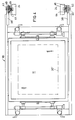
- the device shown in FIGS. 1 and 2 essentially consists of a screen printing stencil device 10, which has a screen printing stencil 11 arranged within a frame 12 and interacts with a doctor blade 14 and a counter pressure roller 16. Squeegee 14 and counter-pressure roller 16 are carried by a common carriage 18 which is arranged such that it can be moved back and forth in the horizontal plane and is guided on bars 20. The latter are attached to vertical stands 22 which are connected to the machine frame 24.
- the carriage 18 is driven by a crank mechanism 15, the crank 17 of which is arranged to be pivotable about an axis 19.
- the carriage 18 is provided with a horizontal guide slot 21 extending transversely to the spars 20, into which a pin 23 of the crank arm 17 engages.
- the counter pressure roller 16 is assigned a guide roller 26 which is also carried by the carriage 18. Both rollers 16 and 26 serve to guide the material 28 to be printed, which is web-shaped and is printed in batches when the web 28 between two Transport steps stand still.
- the web-shaped material 28 to be printed can be drawn off from a supply roll and rolled up again after printing.
- the screen printing stencil device 10 is inclined by an angle 34 (FIG. 3) relative to the horizontal distance 30, which the carriage 18 and thus the counter-pressure roller 16 can be displaced in the direction of the arrow 32 during the printing stroke, as in the embodiment shown in the drawing Is 15 °.
- the carriage 18 is provided with a sliding guide 36 for the screen printing stencil device 10.
- This slide guide 36 is also arranged at an angle of 15 ° to the horizontal, that is to say corresponding to the angle 34 with respect to the spars 20, which determine the course of the distance by which the carriage 18 with the counter-pressure roller and doctor blade 14 during the pressure stroke in the direction of arrow 32 is moved.
- the screen printing stencil device 10 is also provided at the lower end region with two lateral, downwardly projecting extensions 38, each of which carries a holder 40 which can be pivoted about an axis 41 on the respective extension 38 in a vertical plane running parallel to the spars 20 is appropriate.
- Each bracket 40 carries three rollers, which are arranged in the manner shown in Figures 1 and 2 of the drawing to each other and each cooperate with a guide bar 42 such that two rollers 44 on one side and the roller 46 on the other side of the bar 42 are located and bear against the bar 42 such that the rollers 44, 46 and thus the parts carrying them can be easily moved along the bar 42. Since the rollers 44 and 46 each have holder 40 and extension 38 with the sieve Printing stencil device 10 are connected, the strips 42 thus represent a guide for the screen printing stencil.
- the counter-pressure roller 16 brings the portion of the web-shaped material to be printed into contact with the screen printing stencil 11, the doctor blade 14, which is also attached to the carriage 18, applying the printing ink through the printing stencil to produce the print image on the web-shaped material.
- the length of the printed image 30 ⁇ copied into the screen printing stencil 22 is equal to the length of the distance 30 by which the counter-pressure roller 16 is moved during the printing stroke. Due to the inclined arrangement of the screen printing stencil 11 with respect to the course of the path 30, the projection of the printed image 30 ′ copied into the screen printing stencil 11 onto the path 30 is shorter.
- FIG. 3 of the drawing shows the geometric relationships between the movement path 30 of the counterpressure roller 16 and the screen printing stencil 11 or the printed image 30 'located therein.
- An arrangement of the screen printing stencil device 10, in which the screen printing stencil 11 runs parallel to the distance which is carried out by the counterpressure roller 16 during the printing stroke, is undesirable since the oblique arrangement of the screen printing stencil device 10 is approximately horizontal with the printed section of the web-like material 28 in the course of the printing stroke, that is to say the movement of the counterpressure roller 16 in the direction of the arrow 32, causes the web-shaped material 28 to be properly detached from the screen printing stencil as soon as the web-shaped material 28 provided with the ink application during the printing stroke causes the area between screen printing stencil 11 and counterpressure roller 16 leaves.
- the inclined arrangement of the screen printing stencil device 10 enables the color to be properly distributed over the area of the screen printing stencil 11 provided with the printed image and the ink to be collected in the lower area of the screen printing stencil. This also favors good print quality.
- the angle of inclination 34 is 15 °, in many applications this is a kind of optimum between the aforementioned printing requirements and the length difference caused by the inclination of the screen printing stencil relative to the distance 30 between this distance and the printed image 30 'projected onto it, that in the screen printing stencil is copied in.
- This difference in length must be compensated during the printing process if it is to be prevented that the printed image appearing on the web-shaped material 28 only has the length of the projection of the printed image 30 ⁇ on the path 30, and would therefore be shorter than the actual length of the one copied into the screen printing stencil 11 Print image corresponds to 30 ⁇ .
- This compensation is achieved in that the screen printing stencil device 10 with the screen printing stencil 11 experiences a shift parallel to its main plane during the printing process, that is to say during the printing stroke carried out by the counterpressure roller 16.
- This parallel displacement which overlaps the upward displacement of the screen printing stencil device 10 caused by the slide bearings 36, takes place, based on the illustration in FIGS. 1 to 3, from left to right, that is to say essentially in the direction in which the pressure roller 16 moves during the pressure stroke.
- Fig. 3 shows that at the beginning of the printing process, the screen printing stencil 11 assumes a position in which the left end of the printed image 30 ⁇ copied into it lies at the starting point of the stroke which the counter-pressure roller 16 carries out along the path 30 during the printing process. In this position, the printed image 30 ⁇ ends before the end of this distance 30. Because of the displacement of the screen printing stencil device 10 to the right is the right end of the printed image 30 'copied into the screen printing stencil 11 at the end of the printing stroke and also at the end of the path 30.
- the path 30' which runs parallel to the screen printing stencil 11, denotes the distance between the left end of the in the screen printing stencil copied print image 30sent at the beginning of the printing process on the one hand, i.e.
- the angle of inclination 48 of the guide strips 42 must each be half of the angle 34 by which the screen printing stencil device 10 is inclined relative to the path 30 or the spars 20. Therefore, the angle 48 is 7.5 ° if the angle 34 is 15 °.
- the guide strips 42 are pivotably attached to the screen printing machine about an axis 50, which is located near the lower end of the respective strip, in a vertical plane which runs parallel to the path 30.
- the angle 48, which the guide strips 42 form with the vertical, can thus be changed by correspondingly pivoting the strips 42. This is expedient, if necessary even if the length 30 'of the printed image copied into the screen printing stencil differs from the desired length of the printed image to be applied to the web-shaped material. This can occur if the web-like material is printed two or more times and the time intervals between the individual Printing processes are so large that the web-shaped material undergoes a change in its length between two passes through the printing press.
- the print image already applied to material 58 in the first pass becomes shorter, with the result that the new print image to be applied must also be shorter than the length 30 ⁇ of the one in the template located print image corresponds.
- This is also effected by a corresponding pivoting of the guide strips 42 about the respective pivot axis 50, but in the opposite direction, that is to say in the sense of a reduction in the angle 48, so that the parallel displacement carried out by the screen printing stencil device during the printing process becomes correspondingly shorter.
- the extent of the parallel displacement corresponds in this case to the difference between the path section for the compensation of the length difference 30 ⁇ -30 resulting from the angle 34 and the path section that the adaptation of the length of the printed image 30sent copied into the screen printing stencil to the length of the printed image serves on the web-shaped material.
- the extent to which the guide strips 42 are pivoted out of their normal position is very small. It will normally be on the order of, for example, +1 ° to 3 °. However, this is sufficient to achieve the required adaptation of the length of the newly applied print image to the print image which has already become longer or shorter due to the change in length of the web-shaped material 28 and is already on the material 28.
- the changes in length of the print image to be applied are in any case so small, at least in relation to the total length of the print image to be produced, that the quality of the overall print image, which is composed of several individual print images, does not suffer.
- the invention can also be used when it comes to the production of a printed image which is only produced in a single printing process, that is to say is not composed of a plurality of individual printed images.
- the invention makes it possible to take into account a later change in length of the web-shaped material from the outset in such a way that by adjusting the screen printing stencil or the guide means accordingly, a somewhat longer or shorter print image is applied to the web-shaped material than the desired print image length corresponds.
- the extent to which the printed image applied to the web-shaped material is shorter or longer compared to the desired printed image length can correspond to the extent of the change in length which the web undergoes at a later point in time, for example during a subsequent drying process.
- the web will shrink, that is to say become somewhat shorter, so that the printed image applied to the web-shaped material is somewhat longer, namely in accordance with the extent to which the web-shaped material shrinks, than the desired printed image length.
- the printed image copied into the screen printing stencil accordingly longer.
- this would not take into account the fact that, for example, when the material from which the web to be printed is made changes, the extent of the change in length which occurs, for example due to the heat treatment already mentioned, may change. This can be done by adjusting the screen printing template accordingly or the guide for this are taken into account, but not by changing the length of the printed image copied into the screen printing stencil.
- the finished print image is composed of several individual print images
- the screen printing template or the guide for it to be applied correspondingly longer or shorter such that after the length of the web-like material has changed, the length of the first individual printed image essentially corresponds to the desired length.
Landscapes
- Engineering & Computer Science (AREA)
- Mechanical Engineering (AREA)
- Printing Methods (AREA)
- Screen Printers (AREA)
Applications Claiming Priority (2)
| Application Number | Priority Date | Filing Date | Title |
|---|---|---|---|
| DE19873738836 DE3738836A1 (de) | 1987-11-16 | 1987-11-16 | Verfahren und vorrichtung zum bedrucken von bahnfoermigem material |
| DE3738836 | 1987-11-16 |
Publications (3)
| Publication Number | Publication Date |
|---|---|
| EP0316632A2 true EP0316632A2 (fr) | 1989-05-24 |
| EP0316632A3 EP0316632A3 (en) | 1990-05-16 |
| EP0316632B1 EP0316632B1 (fr) | 1993-04-14 |
Family
ID=6340576
Family Applications (1)
| Application Number | Title | Priority Date | Filing Date |
|---|---|---|---|
| EP88117881A Expired - Lifetime EP0316632B1 (fr) | 1987-11-16 | 1988-10-27 | Procédé et dispositif pour l'impression de matériau en bande |
Country Status (3)
| Country | Link |
|---|---|
| US (1) | US4809605A (fr) |
| EP (1) | EP0316632B1 (fr) |
| DE (3) | DE8717654U1 (fr) |
Families Citing this family (2)
| Publication number | Priority date | Publication date | Assignee | Title |
|---|---|---|---|---|
| US5735806A (en) * | 1996-02-23 | 1998-04-07 | Leibovic; Stephen J. | Wrist traction apparatus |
| US20060222828A1 (en) * | 2005-04-01 | 2006-10-05 | John Boyle & Company, Inc. | Recyclable display media |
Family Cites Families (13)
| Publication number | Priority date | Publication date | Assignee | Title |
|---|---|---|---|---|
| US2623456A (en) * | 1948-03-24 | 1952-12-30 | Mccormick William Philip | Stenciling machine |
| US2991711A (en) * | 1954-09-24 | 1961-07-11 | Frank Sche Eisenwerke Ag | Fully automatic silk-screen printing machine |
| US3101665A (en) * | 1961-08-03 | 1963-08-27 | Gardner V Hall | Silk screen printing press |
| US4063502A (en) * | 1975-11-17 | 1977-12-20 | Cunningham Leroy G | Squeegee and flood-bar drive with screen lift |
| SE398076B (sv) * | 1976-09-28 | 1977-12-05 | Svecia Silkscreen Maskiner Ab | Stenciltryckmaskin |
| DE2810690A1 (de) * | 1978-03-11 | 1979-09-20 | Kammann Maschf Werner | Siebdruckverfahren und vorrichtung zu dessen durchfuehrung |
| DE2932099A1 (de) * | 1979-08-08 | 1981-02-26 | Kammann Maschf Werner | Siebdruckmaschine |
| DE2940113A1 (de) * | 1979-10-03 | 1981-06-25 | Werner Kammann Maschinenfabrik GmbH, 4980 Bünde | Verfahren zum bedrucken eines objektes und siebdruckvorrichtung zur durchfuehrung des verfahrens |
| DE2943893C2 (de) * | 1979-10-31 | 1984-12-20 | Gerhard Ing.(grad.) 4800 Bielefeld Klemm | Vorrichtung zum Bedrucken von Warenbahnen mit einer Siebdruckstation |
| US4520726A (en) * | 1982-10-18 | 1985-06-04 | Societe D'exploitation Des Machines Dubuit | Flat silk-screen printing machine with movable pivoted support |
| DE3334444A1 (de) * | 1983-09-23 | 1985-04-11 | Gerhard 4800 Bielefeld Klemm | Siebdruckmaschine |
| US4493254A (en) * | 1983-10-31 | 1985-01-15 | Lawson Printing Machines Company, Inc. | Screen printing machine and drive system therefor |
| FR2570022B1 (fr) * | 1984-09-11 | 1988-09-23 | David Bernard | Machine de serigraphie |
-
1987
- 1987-11-16 DE DE8717654U patent/DE8717654U1/de not_active Expired
- 1987-11-16 DE DE19873738836 patent/DE3738836A1/de not_active Withdrawn
-
1988
- 1988-01-28 US US07/149,263 patent/US4809605A/en not_active Expired - Lifetime
- 1988-10-27 DE DE8888117881T patent/DE3880264D1/de not_active Expired - Fee Related
- 1988-10-27 EP EP88117881A patent/EP0316632B1/fr not_active Expired - Lifetime
Also Published As
| Publication number | Publication date |
|---|---|
| DE8717654U1 (de) | 1989-09-21 |
| DE3880264D1 (de) | 1993-05-19 |
| EP0316632A3 (en) | 1990-05-16 |
| EP0316632B1 (fr) | 1993-04-14 |
| US4809605A (en) | 1989-03-07 |
| DE3738836A1 (de) | 1989-05-24 |
Similar Documents
| Publication | Publication Date | Title |
|---|---|---|
| DE4224235C5 (de) | Breiten-Einstellvorrichtung für eine Papierbahn, sowie damit ausgestattete Rotationspresse | |
| EP0362976B1 (fr) | Dispositif pour alimenter un matériau en bande à une station de traitement | |
| DE4327646C5 (de) | Breiten-Einstellverfahren für eine Papierbahn sowie damit ausgerüstete lithographische Rotationspresse | |
| DE2810690C2 (fr) | ||
| DE3830724C2 (fr) | ||
| EP0135618B1 (fr) | Machine de sérigraphie | |
| EP1595837A1 (fr) | Structure de pliage et procédé pour le traitement d'une bande | |
| EP0316632B1 (fr) | Procédé et dispositif pour l'impression de matériau en bande | |
| DE2619800C2 (de) | Trockenvorrichtung für Druckmaschinen | |
| DE3336792C2 (fr) | ||
| DE2612275A1 (de) | Druckerpresse zur verwendung in verbindung mit taschenherstellungsmaschinen | |
| DE3503715C2 (fr) | ||
| DE2632022A1 (de) | Vorrichtung zum erzeugen eines gleichmaessigen spannungszustandes in einer warenbahn | |
| DE1224334B (de) | Siebdruckverfahren und -vorrichtung | |
| DE2026050A1 (de) | Verfahren zum Herstellen mehrerer Bahn einheiten | |
| DE2365668C3 (de) | Vorrichtung zur Verarbeitung bahnförmigen Materials mit einem Rotationsdruckwerk | |
| DE19838983A1 (de) | Siebdruckvorrichtung | |
| EP0421138B1 (fr) | Dispositif de recouvrement pour tissu pour imprimer au pochoir | |
| DE3225375A1 (de) | Vorrichtung zum ausrichten zum zwecke des faden- und/oder druckgeraden trennens einer verzogenen bahnfoermigen ware, insbesondere einer textilbahn | |
| DE2113843A1 (de) | Druckvorrichtung | |
| DE517501C (de) | Zylinderschnellpresse mit hin und her schwingendem Druckzylinder | |
| EP0123049B1 (fr) | Machine à imprimer comportant un cylindre d'impression, en particulier machine sérigraphique | |
| DE1177464B (de) | Verfahren und Anordnung zum fortlaufenden Bearbeiten von fuer Formularsaetze bestimmten Papierbahnen | |
| DE8304988U1 (de) | Mit Gegendruckwalze arbeitende Druckmaschine, vorzugsweise Siebdruckmaschine | |
| DE2430472C2 (de) | Wagen an Rotationsdruckrnaschinen |
Legal Events
| Date | Code | Title | Description |
|---|---|---|---|
| PUAI | Public reference made under article 153(3) epc to a published international application that has entered the european phase |
Free format text: ORIGINAL CODE: 0009012 |
|
| AK | Designated contracting states |
Kind code of ref document: A2 Designated state(s): DE ES FR GB IT |
|
| PUAL | Search report despatched |
Free format text: ORIGINAL CODE: 0009013 |
|
| AK | Designated contracting states |
Kind code of ref document: A3 Designated state(s): DE ES FR GB IT |
|
| 17P | Request for examination filed |
Effective date: 19901108 |
|
| 17Q | First examination report despatched |
Effective date: 19920930 |
|
| GRAA | (expected) grant |
Free format text: ORIGINAL CODE: 0009210 |
|
| ITF | It: translation for a ep patent filed | ||
| AK | Designated contracting states |
Kind code of ref document: B1 Designated state(s): DE ES FR GB IT |
|
| PG25 | Lapsed in a contracting state [announced via postgrant information from national office to epo] |
Ref country code: ES Free format text: THE PATENT HAS BEEN ANNULLED BY A DECISION OF A NATIONAL AUTHORITY Effective date: 19930414 |
|
| REF | Corresponds to: |
Ref document number: 3880264 Country of ref document: DE Date of ref document: 19930519 |
|
| GBT | Gb: translation of ep patent filed (gb section 77(6)(a)/1977) |
Effective date: 19930527 |
|
| ET | Fr: translation filed | ||
| ITTA | It: last paid annual fee | ||
| PLBE | No opposition filed within time limit |
Free format text: ORIGINAL CODE: 0009261 |
|
| STAA | Information on the status of an ep patent application or granted ep patent |
Free format text: STATUS: NO OPPOSITION FILED WITHIN TIME LIMIT |
|
| 26N | No opposition filed | ||
| PGFP | Annual fee paid to national office [announced via postgrant information from national office to epo] |
Ref country code: GB Payment date: 19991027 Year of fee payment: 12 |
|
| PG25 | Lapsed in a contracting state [announced via postgrant information from national office to epo] |
Ref country code: GB Free format text: LAPSE BECAUSE OF NON-PAYMENT OF DUE FEES Effective date: 20001027 |
|
| PGFP | Annual fee paid to national office [announced via postgrant information from national office to epo] |
Ref country code: FR Payment date: 20001027 Year of fee payment: 13 |
|
| GBPC | Gb: european patent ceased through non-payment of renewal fee |
Effective date: 20001027 |
|
| PG25 | Lapsed in a contracting state [announced via postgrant information from national office to epo] |
Ref country code: FR Free format text: LAPSE BECAUSE OF NON-PAYMENT OF DUE FEES Effective date: 20020628 |
|
| REG | Reference to a national code |
Ref country code: FR Ref legal event code: ST |
|
| PGFP | Annual fee paid to national office [announced via postgrant information from national office to epo] |
Ref country code: DE Payment date: 20041229 Year of fee payment: 17 |
|
| PG25 | Lapsed in a contracting state [announced via postgrant information from national office to epo] |
Ref country code: IT Free format text: LAPSE BECAUSE OF NON-PAYMENT OF DUE FEES Effective date: 20051027 |
|
| PG25 | Lapsed in a contracting state [announced via postgrant information from national office to epo] |
Ref country code: DE Free format text: LAPSE BECAUSE OF NON-PAYMENT OF DUE FEES Effective date: 20060503 |