EP0313954B1 - Verriegelungsanordnung für zwei Schaltgeräte, vorzugsweise Schütze - Google Patents
Verriegelungsanordnung für zwei Schaltgeräte, vorzugsweise Schütze Download PDFInfo
- Publication number
- EP0313954B1 EP0313954B1 EP88117260A EP88117260A EP0313954B1 EP 0313954 B1 EP0313954 B1 EP 0313954B1 EP 88117260 A EP88117260 A EP 88117260A EP 88117260 A EP88117260 A EP 88117260A EP 0313954 B1 EP0313954 B1 EP 0313954B1
- Authority
- EP
- European Patent Office
- Prior art keywords
- locking
- guide housing
- arrangement according
- locking arrangement
- heart
- Prior art date
- Legal status (The legal status is an assumption and is not a legal conclusion. Google has not performed a legal analysis and makes no representation as to the accuracy of the status listed.)
- Expired - Lifetime
Links
- 230000001681 protective effect Effects 0.000 title 1
- 230000003213 activating effect Effects 0.000 claims 1
- 230000004913 activation Effects 0.000 claims 1
- 238000013459 approach Methods 0.000 description 3
- 230000008878 coupling Effects 0.000 description 3
- 238000010168 coupling process Methods 0.000 description 3
- 238000005859 coupling reaction Methods 0.000 description 3
- 230000005540 biological transmission Effects 0.000 description 1
- 230000015572 biosynthetic process Effects 0.000 description 1
- 230000007246 mechanism Effects 0.000 description 1
- 238000010079 rubber tapping Methods 0.000 description 1
Images
Classifications
-
- H—ELECTRICITY
- H01—ELECTRIC ELEMENTS
- H01H—ELECTRIC SWITCHES; RELAYS; SELECTORS; EMERGENCY PROTECTIVE DEVICES
- H01H50/00—Details of electromagnetic relays
- H01H50/16—Magnetic circuit arrangements
- H01H50/18—Movable parts of magnetic circuits, e.g. armature
- H01H50/32—Latching movable parts mechanically
- H01H50/323—Latching movable parts mechanically for interlocking two or more relays
Definitions
- the invention relates to a locking arrangement for two switching devices, which are coupled via a locking body in such a way that when a switching device is actuated, the other switching device acting in the opposite sense on the locking body is locked in its actuating movement, the essentially heart-shaped locking body with the tip of the heart in a guide housing which can be fastened separately from the switching devices is guided, the heart wings being operatively connected to the actuating means of the switching devices via plunger and adjusting means.
- the guide housing is firmly screwed to the mounting plate via a U-bracket.
- the switching devices here contactors, are provided with two-armed levers which are pivotally connected to the actuating means of the contactor between a support point on the contactor housing and the connection with the plungers guided in the guide housing. Adjusting screws are provided on the ends of the levers connected to the tappets, which can be secured with lock nuts.
- the heart-shaped locking body is suspended from a spring in the guide housing. Due to the spring here, however, a certain amount of play cannot be switched off, so that relatively large distances for the plunger have to be accepted, which is achieved by the elaborately arranged levers.
- the invention is therefore based on the object of providing an arrangement of the type mentioned above which can be used in a versatile manner with a simple structure without lever transmission and simple adjustment possibility.
- the adjusting means consist of collar screws screwed into slides guided in the guide housing, which are rigidly connected to the tappets via their collar in the direction of movement and that the heart wings are essentially rigidly connected to the tappets via drivers in the direction of movement .
- a simple connection of the slide to the actuating means can be achieved if the slides are positively coupled via approaches which engage in the actuating means of the switching devices.
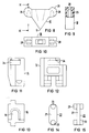
- feet which are adjustable in length are arranged on the guide housing, it being possible to simply attach the feet if they can be pivoted into a toothing of the guide housing prior to attachment to the mounting plate and the feet are fitted with a C- gripping part of trapezoidal form of the two-part guide housing, it is possible to dispense with connecting means of the housing parts.
- the height adjustment in relation to different contactors can be achieved in a simple manner here in that the feet on the bottom of the C-shaped part and the trapezoidal projections on the surface facing away from the housing are provided with locking teeth.
- a simple coupling between the plunger and locking body, which is effective in both directions of movement, can be achieved if the drivers are H-shaped and are inserted transversely to the direction of movement into adapted recesses in the plunger and locking body.
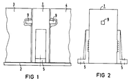
- the locking arrangement 1 is fastened on the mounting plate 2 between two contactors 3 and 4.
- feet 5 are used, which - as shown in FIG. 3 - can be pivoted into a toothing 6 before assembly.
- the setting position is indicated by dashed lines in FIG.
- the feet 5 are supported on brackets 7 of the guide housing 8 of the locking arrangement 1 and are then screwed to the mounting plate 2 with fastening screws, not shown.
- the length of the feet 5 determines the point of engagement of the shoulder 9, which engage in the actuator for the contactors 3, 4, not shown in detail.
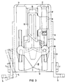
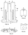
- the feet can also be formed with a C-shaped part 30, as shown in FIG. 19.
- This C-shaped part can connect trapezoidal projections 31 of the two guide housing parts 8a and 8b to one another, as shown in FIG.
- the projections 31 can here be formed on the side facing away from the guide housing with a toothing as a toothed strip, which cooperate with further catches provided on the bottom of the C-shaped part 30.
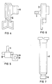
- the heart-shaped locking body 10 is guided with the heart tip 11 on the locking curve 12 in the guide housing 8. Furthermore, the slide 13 and the plunger 14 are slidably mounted in the guide housing. The slides 13 engage with the lugs 9 through guide slots 15 in the two halves of the guide housing 8. A lateral projection 16 on the slide 13 serves for connection to the respective plunger 14.
- the collar screw 17 is used for this purpose. The collar 18 is inserted into a laterally open recess 19 of the plunger 14 after it has been self-tapping Screw was screwed into the hole 20 in the formation 16.
- an H-shaped driver 22 is provided, which is inserted with one of the H-arms 23 into a hammer head-shaped recess 24 in the plunger 14 transversely to the direction of actuation.
- the other H-arms 23 are inserted into a corresponding recess 25 in the heart wings 26 and in such a way that the web 27 of the heart shape can be passed through the slot 28 in the heart wing 26.
- the connection is made in such a way that the plunger 14 slide on the curved surface 29 when the locking body moves and this more or less in both directions of movement of the plunger 14. This positive connection of the slide 13, plunger 14 and locking body 10 pulls the locking body back into the central position without the need for an additional spring.
- the locking body 11 is also removed from the locking curve 12, ie the heads of the collar screws come out through the actuation holes 21 of the guide housing.
- the length of the collar screws 17 is now selected such that after the collar screws have been screwed in in the direction of the mounting surface of the locking arrangement, until the surface of the head is flush with the surface of the guide housing, the predetermined one Position of the heart-shaped locking body 10 to the locking curve 12 is present, as can be seen for example from FIG. 3.
Landscapes
- Physics & Mathematics (AREA)
- Electromagnetism (AREA)
- Switch Cases, Indication, And Locking (AREA)
- Transmission Devices (AREA)
- Mechanisms For Operating Contacts (AREA)
- Infusion, Injection, And Reservoir Apparatuses (AREA)
Applications Claiming Priority (2)
| Application Number | Priority Date | Filing Date | Title |
|---|---|---|---|
| DE8714499U DE8714499U1 (de) | 1987-10-30 | 1987-10-30 | Verriegelungsbaustein für zwei Schaltgeräte, vorzugsweise Schütze |
| DE8714499U | 1987-10-30 |
Publications (2)
| Publication Number | Publication Date |
|---|---|
| EP0313954A1 EP0313954A1 (de) | 1989-05-03 |
| EP0313954B1 true EP0313954B1 (de) | 1992-05-06 |
Family
ID=6813610
Family Applications (1)
| Application Number | Title | Priority Date | Filing Date |
|---|---|---|---|
| EP88117260A Expired - Lifetime EP0313954B1 (de) | 1987-10-30 | 1988-10-17 | Verriegelungsanordnung für zwei Schaltgeräte, vorzugsweise Schütze |
Country Status (4)
| Country | Link |
|---|---|
| US (1) | US4883927A (enExample) |
| EP (1) | EP0313954B1 (enExample) |
| JP (1) | JPH0739141Y2 (enExample) |
| DE (2) | DE8714499U1 (enExample) |
Cited By (2)
| Publication number | Priority date | Publication date | Assignee | Title |
|---|---|---|---|---|
| DE29706431U1 (de) * | 1997-04-10 | 1997-06-12 | Siemens AG, 80333 München | Verriegelungsbaustein für Schütze |
| DE29706428U1 (de) * | 1997-04-10 | 1997-06-12 | Siemens AG, 80333 München | Verriegelungsbaustein |
Families Citing this family (8)
| Publication number | Priority date | Publication date | Assignee | Title |
|---|---|---|---|---|
| DE3813100A1 (de) * | 1988-04-19 | 1989-11-02 | Asea Brown Boveri | Kombination zweier elektrischer schaltgeraete mit einer deren einschaltmoeglichkeit beeinflussenden sperrvorrichtung |
| FR2643190B1 (fr) * | 1989-02-16 | 1996-04-26 | Merlin Gerin | Module d'interverrouillage de deux appareils electriques a boitier moule miniature |
| JP2923736B2 (ja) * | 1994-08-18 | 1999-07-26 | 春日電機株式会社 | 多段階操作インタ−ロック付押釦開閉器 |
| DE19548480C1 (de) * | 1995-12-22 | 1997-05-22 | Siemens Ag | Schaltgeräteeinheit |
| CN1258794C (zh) | 1999-09-27 | 2006-06-07 | 西门子公司 | 接触器装置 |
| JP5018905B2 (ja) * | 2010-01-27 | 2012-09-05 | 富士電機機器制御株式会社 | 電磁接触器ユニット |
| BR112014011657A2 (pt) * | 2011-11-17 | 2017-05-02 | Abb Ab | mecanismo de intertravamento |
| JP7314807B2 (ja) * | 2020-01-21 | 2023-07-26 | 富士電機機器制御株式会社 | 電磁接触器 |
Family Cites Families (4)
| Publication number | Priority date | Publication date | Assignee | Title |
|---|---|---|---|---|
| US3149210A (en) * | 1961-03-13 | 1964-09-15 | Allen Bradley Co | Mechanical interlock |
| DE1902103A1 (de) * | 1969-01-16 | 1970-08-13 | Bogen Gmbh W | Magnetkopf |
| DE7926469U1 (de) * | 1979-09-18 | 1979-12-13 | Siemens Ag, 1000 Berlin Und 8000 Muenchen | Verriegelungseinrichtung für Kontaktträger |
| DE2951356C2 (de) * | 1979-12-20 | 1985-05-09 | Brown, Boveri & Cie Ag, 6800 Mannheim | Vorrichtung zur mechanischen Einschaltsperrung eines von zwei Schaltorganen, solange sich das andere Schaltorgan in eingeschalteter Stellung befindet |
-
1987
- 1987-10-30 DE DE8714499U patent/DE8714499U1/de not_active Expired
-
1988
- 1988-10-17 EP EP88117260A patent/EP0313954B1/de not_active Expired - Lifetime
- 1988-10-17 DE DE8888117260T patent/DE3870805D1/de not_active Expired - Lifetime
- 1988-10-28 JP JP1988141878U patent/JPH0739141Y2/ja not_active Expired - Lifetime
- 1988-10-28 US US07/264,200 patent/US4883927A/en not_active Expired - Fee Related
Cited By (2)
| Publication number | Priority date | Publication date | Assignee | Title |
|---|---|---|---|---|
| DE29706431U1 (de) * | 1997-04-10 | 1997-06-12 | Siemens AG, 80333 München | Verriegelungsbaustein für Schütze |
| DE29706428U1 (de) * | 1997-04-10 | 1997-06-12 | Siemens AG, 80333 München | Verriegelungsbaustein |
Also Published As
| Publication number | Publication date |
|---|---|
| JPH0739141Y2 (ja) | 1995-09-06 |
| US4883927A (en) | 1989-11-28 |
| DE3870805D1 (de) | 1992-06-11 |
| EP0313954A1 (de) | 1989-05-03 |
| DE8714499U1 (de) | 1988-01-21 |
| JPH0171831U (enExample) | 1989-05-15 |
Similar Documents
| Publication | Publication Date | Title |
|---|---|---|
| DE69810553T2 (de) | Einrichtung zum Halten der Position von zwei Bauteilen mit steigbügelartiger Befestigungsvorrichtung | |
| EP0606564A1 (de) | Verstelleinrichtung zur Ausrichtung eines Schubkastens, Auszuges oder dergleichen | |
| EP0313954B1 (de) | Verriegelungsanordnung für zwei Schaltgeräte, vorzugsweise Schütze | |
| DE1959155C3 (de) | Elektrischer Schnappschalter | |
| EP0173756B1 (de) | Kontaktvorrichtung | |
| EP3225133A1 (de) | Höhenverstellbare armlehne | |
| DE3149518A1 (de) | Sicherheitsgurtsystem fuer kraftfahrzeuge | |
| EP0209832A2 (de) | Druckknopfbetätigter Überstromschutzschalter | |
| WO1991018173A1 (de) | Möbelscharnier | |
| DE3228803A1 (de) | Skibremse | |
| DE3151019A1 (de) | Vorrichtung zum befestigen des oberen umlenkbeschlages fuer einen dreipunktsicherheitsgurt an der karosserie eines kraftfahrzeuges | |
| EP0761132A1 (de) | Verstelleinrichtung zur Ausrichtung eines auf Laufschienen gelagerten Schubkastens, Auszuges oder dergleichen | |
| DE3713775A1 (de) | Tastenschalter | |
| DE3225862A1 (de) | Vorrichtung zur stufenweisen hoehenverstellung und befestigung des oberen umlenkbeschlages fuer einen sicherheitsgurt | |
| DE2425520A1 (de) | Schiebeschalter | |
| DE2144756C3 (de) | Fernbetätigungsvorrichtung, insbesondere für Kraftfahrzeugtürschlösser | |
| EP3311695A1 (de) | Rasteinrichtung und längenverstellbare stütze | |
| DE4025068C2 (enExample) | ||
| DE2754300C3 (de) | Schaltkopf für einen Endschalter | |
| DE1263136B (de) | Stoesselschnappschalter mit zwei Ein-Stellungen und einer dazwischenliegenden Aus-Stellung | |
| DE2056446A1 (de) | Ein Aus Schalter mit Freiauslosung | |
| DE2816185A1 (de) | Rasteinrichtung fuer einen drucktastenschalter | |
| EP0278894B1 (de) | Mechanische Verriegelungseinrichtung für elektrische Schaltgeräte | |
| DE3324253A1 (de) | Tastenschalter | |
| DE3136872C2 (enExample) |
Legal Events
| Date | Code | Title | Description |
|---|---|---|---|
| PUAI | Public reference made under article 153(3) epc to a published international application that has entered the european phase |
Free format text: ORIGINAL CODE: 0009012 |
|
| AK | Designated contracting states |
Kind code of ref document: A1 Designated state(s): CH DE FR GB IT LI SE |
|
| 17P | Request for examination filed |
Effective date: 19890627 |
|
| 17Q | First examination report despatched |
Effective date: 19911009 |
|
| GRAA | (expected) grant |
Free format text: ORIGINAL CODE: 0009210 |
|
| AK | Designated contracting states |
Kind code of ref document: B1 Designated state(s): CH DE FR GB IT LI SE |
|
| REF | Corresponds to: |
Ref document number: 3870805 Country of ref document: DE Date of ref document: 19920611 |
|
| ITF | It: translation for a ep patent filed | ||
| ET | Fr: translation filed | ||
| GBT | Gb: translation of ep patent filed (gb section 77(6)(a)/1977) | ||
| PLBE | No opposition filed within time limit |
Free format text: ORIGINAL CODE: 0009261 |
|
| STAA | Information on the status of an ep patent application or granted ep patent |
Free format text: STATUS: NO OPPOSITION FILED WITHIN TIME LIMIT |
|
| 26N | No opposition filed | ||
| PGFP | Annual fee paid to national office [announced via postgrant information from national office to epo] |
Ref country code: CH Payment date: 19940118 Year of fee payment: 6 |
|
| PGFP | Annual fee paid to national office [announced via postgrant information from national office to epo] |
Ref country code: GB Payment date: 19940916 Year of fee payment: 7 |
|
| PG25 | Lapsed in a contracting state [announced via postgrant information from national office to epo] |
Ref country code: LI Effective date: 19941031 Ref country code: CH Effective date: 19941031 |
|
| EAL | Se: european patent in force in sweden |
Ref document number: 88117260.5 |
|
| REG | Reference to a national code |
Ref country code: CH Ref legal event code: PL |
|
| PG25 | Lapsed in a contracting state [announced via postgrant information from national office to epo] |
Ref country code: GB Effective date: 19951017 |
|
| GBPC | Gb: european patent ceased through non-payment of renewal fee |
Effective date: 19951017 |
|
| PGFP | Annual fee paid to national office [announced via postgrant information from national office to epo] |
Ref country code: SE Payment date: 19961022 Year of fee payment: 9 |
|
| PG25 | Lapsed in a contracting state [announced via postgrant information from national office to epo] |
Ref country code: SE Free format text: LAPSE BECAUSE OF NON-PAYMENT OF DUE FEES Effective date: 19971018 |
|
| EUG | Se: european patent has lapsed |
Ref document number: 88117260.5 |
|
| PGFP | Annual fee paid to national office [announced via postgrant information from national office to epo] |
Ref country code: FR Payment date: 20001027 Year of fee payment: 13 |
|
| PGFP | Annual fee paid to national office [announced via postgrant information from national office to epo] |
Ref country code: DE Payment date: 20001218 Year of fee payment: 13 |
|
| PG25 | Lapsed in a contracting state [announced via postgrant information from national office to epo] |
Ref country code: FR Free format text: LAPSE BECAUSE OF NON-PAYMENT OF DUE FEES Effective date: 20020628 |
|
| PG25 | Lapsed in a contracting state [announced via postgrant information from national office to epo] |
Ref country code: DE Free format text: LAPSE BECAUSE OF NON-PAYMENT OF DUE FEES Effective date: 20020702 |
|
| REG | Reference to a national code |
Ref country code: FR Ref legal event code: ST |
|
| PG25 | Lapsed in a contracting state [announced via postgrant information from national office to epo] |
Ref country code: IT Free format text: LAPSE BECAUSE OF NON-PAYMENT OF DUE FEES;WARNING: LAPSES OF ITALIAN PATENTS WITH EFFECTIVE DATE BEFORE 2007 MAY HAVE OCCURRED AT ANY TIME BEFORE 2007. THE CORRECT EFFECTIVE DATE MAY BE DIFFERENT FROM THE ONE RECORDED. Effective date: 20051017 |