EP0313771B1 - Balkengleisbremse zum Abbremsen von Eisenbahnwaggons - Google Patents
Balkengleisbremse zum Abbremsen von Eisenbahnwaggons Download PDFInfo
- Publication number
- EP0313771B1 EP0313771B1 EP88114489A EP88114489A EP0313771B1 EP 0313771 B1 EP0313771 B1 EP 0313771B1 EP 88114489 A EP88114489 A EP 88114489A EP 88114489 A EP88114489 A EP 88114489A EP 0313771 B1 EP0313771 B1 EP 0313771B1
- Authority
- EP
- European Patent Office
- Prior art keywords
- intermediate layers
- segment
- braking
- cover plate
- lubricant
- Prior art date
- Legal status (The legal status is an assumption and is not a legal conclusion. Google has not performed a legal analysis and makes no representation as to the accuracy of the status listed.)
- Expired - Lifetime
Links
- 230000001050 lubricating effect Effects 0.000 claims description 6
- 238000004080 punching Methods 0.000 claims 1
- 239000000314 lubricant Substances 0.000 description 31
- 229910000831 Steel Inorganic materials 0.000 description 4
- 238000013016 damping Methods 0.000 description 4
- 238000000034 method Methods 0.000 description 4
- 239000010959 steel Substances 0.000 description 4
- 239000000463 material Substances 0.000 description 2
- RYGMFSIKBFXOCR-UHFFFAOYSA-N Copper Chemical compound [Cu] RYGMFSIKBFXOCR-UHFFFAOYSA-N 0.000 description 1
- 208000002599 Smear Layer Diseases 0.000 description 1
- XAGFODPZIPBFFR-UHFFFAOYSA-N aluminium Chemical compound [Al] XAGFODPZIPBFFR-UHFFFAOYSA-N 0.000 description 1
- 229910052782 aluminium Inorganic materials 0.000 description 1
- 230000015572 biosynthetic process Effects 0.000 description 1
- 230000001680 brushing effect Effects 0.000 description 1
- 229910052802 copper Inorganic materials 0.000 description 1
- 239000010949 copper Substances 0.000 description 1
- 238000011161 development Methods 0.000 description 1
- 230000018109 developmental process Effects 0.000 description 1
- 230000000694 effects Effects 0.000 description 1
- 239000003925 fat Substances 0.000 description 1
- 238000005755 formation reaction Methods 0.000 description 1
- 230000005484 gravity Effects 0.000 description 1
- 239000003673 groundwater Substances 0.000 description 1
- 230000003137 locomotive effect Effects 0.000 description 1
- 230000005923 long-lasting effect Effects 0.000 description 1
- 239000007769 metal material Substances 0.000 description 1
- 239000003921 oil Substances 0.000 description 1
- 230000001737 promoting effect Effects 0.000 description 1
- 230000001105 regulatory effect Effects 0.000 description 1
Images


Classifications
-
- B—PERFORMING OPERATIONS; TRANSPORTING
- B61—RAILWAYS
- B61K—AUXILIARY EQUIPMENT SPECIALLY ADAPTED FOR RAILWAYS, NOT OTHERWISE PROVIDED FOR
- B61K7/00—Railway stops fixed to permanent way; Track brakes or retarding apparatus fixed to permanent way; Sand tracks or the like
- B61K7/02—Track brakes or retarding apparatus
- B61K7/04—Track brakes or retarding apparatus with clamping action
Definitions
- the invention relates to a bar track brake for braking railway wagons, each with two bars on either side of a rail, or with two bars on both sides of a rail, which have on their side facing the wagon wheel one or more elongated recesses for receiving at least one strip-shaped segment , which is arranged interchangeably in the relevant recess, with at least one recess being arranged in the relevant segment on the side facing the wagon wheel, in which a cover plate and a plurality of intermediate layers are interchangeable and interchangeable and z. B. are held by screws on the segment and the segments are to be made slidable with the help of a lubricant on their side facing the wagon wheel.
- segmented bar brakes consist of a continuously rolled brake carrier, on the braking surfaces of which individual steel segments are screwed over the entire length. These segments are about 400 mm long and can be isolated from the actual brake carrier with a 5 mm thick damping plate.
- a bar track brake according to the preamble of claim 1 of this patent application is previously known from EP-A-0011317, in which the segments are constructed in a sandwich-like manner and are formed from individual horizontally superimposed plates which are made of different materials.
- This "sandwich package" thus formed as a segment is connected by several screws to a brake carrier made of steel.
- This segment brake beam wears out relatively quickly and only has a narrow area of application for supply brakes. If the running-in speed is over 2 m / s, such brake shoes cannot be used.
- the invention has for its object to improve a bar track brake according to the preamble of claim 1 to the effect that the unpleasant screeching and squeaking noises can practically no longer occur at all speeds occurring in practice.
- a lubricant device is assigned to the segment in question, which, depending on consumption, delivers the lubricant to the braking surface facing the wagon wheel. This makes it possible to automatically lubricate the braking surfaces of the segments, so that the unpleasant screeching and squeaking noises even at speeds below 2 m / s, for. B. at 1.5 m / s, can no longer occur.
- a bar track brake designed according to the invention When using a bar track brake designed according to the invention, it is therefore in your hand to lubricate the braking surfaces of the segments only when a braking process actually occurs. So you don't need lubricants from the outset, e.g. B. pastes or fats, thick to apply to the braking surfaces, in the hope that they would stay here for a longer period of time.
- lubricant consumption only occurs when the lubricant is actually needed during the braking process. This also protects the environment, since oils and greases seep into the subsoil if the segments are lubricated in an uncontrolled manner and could damage the groundwater.
- a bar track brake designed according to the invention can thus reliably avoid the unpleasant squeaking and screeching noises when braking down railroad cars over all speed ranges that occur in practice.
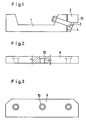
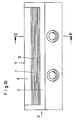
- the reference numeral 1 denotes a beam support, to which a plurality of strip-shaped segments 2 are assigned in its longitudinal direction, which are connected to the beam support 1 by screws. Only one of these screws can be seen in FIG. 1 and has been designated with the reference number 3.
- the Damping element 4 is intended to dampen vibrations and can be made of plastic or another metallic material than the beam support 1 and the segments 2, both of which are forged or rolled from steel.
- Each segment 2 has a recess 5 which is approximately square or rectangular in cross section on its upper side.
- a plurality of sheet-like or sheet-like bodies are arranged, specifically an upper cover sheet 6 and a plurality of sheet-shaped items of equal size located below it Intermediate layers 7.
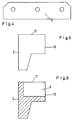
- the number of intermediate layers 7 can be greater or less than nine.
- the thickness of the intermediate layers 7 is considerably smaller than the thickness of the cover plate 6 and can only be about 1/10 to 1/5 of the cover plate 6.
- Both the cover plate 6 and the intermediate layers 7 are made of steel in the illustrated embodiments, but can also be made of different materials, for example aluminum, copper or plastic.
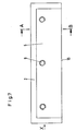
- cover plate 6 The entire package of cover plate 6 and intermediate layers 7 thus formed is held by a plurality of screws 8 (FIG. 8) which are screwed into threaded through bores 9.
- the cover plate 6 has depressions 10, in which the screw heads are each arranged flush with the upper edge 11 of the segments 2.
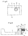
- a lubricating layer 12 is formed as a depot between the intermediate layers 7.
- the lubricant oozes out of this depot to the braking surface 13 and thereby prevents the unpleasant squeaking and screeching across all speed ranges of the railway wagons.
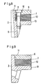
- the beam carrier 1 is assigned a depot chamber 14 for the lubricant, which is connected to the spaces between the intermediate layers 7 via a channel 15 and an extension 16.
- a filling channel 17 is connected to the depot chamber 14, in which a screw 18 is adjustably arranged in order to press the lubricant to the braking surface 13.
- a lubricant pump 19 is provided, which is connected via a line 20 and a connection fitting 21 to a channel 22, which optionally opens into a depot chamber 14, which in turn extends via the extension 16 to the spaces between the intermediate layers 7 is connected, thereby promoting lubricant to the braking surface 13.
- the lubricant pump 19 can also be connected to a plurality of depot chambers, which delivers lubricant to various braking surfaces, for example to a number of further bar track brakes, via a plurality of lines (not shown). It is also possible to connect a plurality of pumps 19 in parallel, which deliver the lubricant to the different braking surfaces 13.
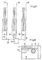
- the intermediate layer 7 is assigned a plurality of depots 23 in the form of a lattice-like structure in which the lubricant is located.
- This can be a sieve-like or otherwise designed sheet with which the lubricant is assigned.
- a sieve-like body 24 is provided for storing the lubricant
- one or more intermediate layers are provided with corrugations 25 which also serve as depots for the lubricant. All the depots, corrugations and sieve-like formations are connected to the intermediate spaces of the intermediate layers 7 and thus to the braking surface 13, so that lubricant can reach the braking surface 13 from here.
- a pump 26 is assigned a plurality - in the present case three - beam track brakes 27, 28 and 29, the depot chambers of which are directed to the relevant ones via lines 30, 31 and 32 and branch lines 34, 35, 36, 37, 38 and 39 Lubricant chambers or depots and thus also connected to the braking surfaces 13 (not shown).
- the pump 26 can be controlled according to a certain program or depending on the braking frequency of the wagons and then deliver suitable lubricant to the braking surfaces 13 so that they remain lubricated continuously.
Landscapes
- Engineering & Computer Science (AREA)
- Mechanical Engineering (AREA)
- Braking Arrangements (AREA)
Priority Applications (1)
| Application Number | Priority Date | Filing Date | Title |
|---|---|---|---|
| AT88114489T ATE66878T1 (de) | 1987-10-29 | 1988-09-05 | Balkengleisbremse zum abbremsen von eisenbahnwaggons. |
Applications Claiming Priority (2)
| Application Number | Priority Date | Filing Date | Title |
|---|---|---|---|
| DE19873736580 DE3736580A1 (de) | 1987-10-29 | 1987-10-29 | Balkengleisbremse zum abbremsen von eisenbahnwaggons |
| DE3736580 | 1987-10-29 |
Publications (2)
| Publication Number | Publication Date |
|---|---|
| EP0313771A1 EP0313771A1 (de) | 1989-05-03 |
| EP0313771B1 true EP0313771B1 (de) | 1991-09-04 |
Family
ID=6339297
Family Applications (1)
| Application Number | Title | Priority Date | Filing Date |
|---|---|---|---|
| EP88114489A Expired - Lifetime EP0313771B1 (de) | 1987-10-29 | 1988-09-05 | Balkengleisbremse zum Abbremsen von Eisenbahnwaggons |
Country Status (4)
| Country | Link |
|---|---|
| EP (1) | EP0313771B1 (cg-RX-API-DMAC10.html) |
| AT (1) | ATE66878T1 (cg-RX-API-DMAC10.html) |
| DE (1) | DE3736580A1 (cg-RX-API-DMAC10.html) |
| ES (1) | ES2023991B3 (cg-RX-API-DMAC10.html) |
Families Citing this family (6)
| Publication number | Priority date | Publication date | Assignee | Title |
|---|---|---|---|---|
| DE3930332C2 (de) * | 1989-09-11 | 1997-08-14 | Siemens Ag | Bremsbalken für Balkengleisbremsen mit segmentierten Verschleißelementen |
| SI20202A (sl) * | 1999-03-10 | 2000-10-31 | Bojan Pav�nik | Protihrupna naprava za tirnične zavore |
| DE10240668A1 (de) * | 2002-09-04 | 2004-03-18 | Cww-Gerko Akustik Gmbh | Balkengleisbremse |
| DE102005054832B3 (de) * | 2005-11-15 | 2007-08-23 | ThyssenKrupp Präzisionsschmide GmbH | Gleisbremse für Schienenfahrzeuge |
| DE202011110091U1 (de) * | 2011-10-07 | 2012-11-22 | Sona Blw Präzisionsschmiede Gmbh | Gleisbremse für Schienenfahrzeuge |
| SI25377A (sl) * | 2017-02-07 | 2018-08-31 | Bojan PAVČNIK | Lamela tirnega elementa, prednostno tirne zavore in postopek njene uporabe |
Family Cites Families (8)
| Publication number | Priority date | Publication date | Assignee | Title |
|---|---|---|---|---|
| US3874298A (en) * | 1972-11-01 | 1975-04-01 | Gen Signal Corp | Noise suppression system for car retarders |
| GB1482999A (en) * | 1973-12-15 | 1977-08-17 | Thyssen Huette Ag | Brake beams for beam-type rail brakes |
| GB1479595A (en) * | 1974-10-29 | 1977-07-13 | Swindells J | Pumps and lubricating devices including pumps |
| US4003451A (en) * | 1975-06-30 | 1977-01-18 | Qiv Incorporated | Low noise brake shoe for track retarder |
| DE2555722B1 (de) * | 1975-12-11 | 1977-05-18 | Andreas Radermacher | An einer fahrschiene angeordnete schienenschmiervorrichtung |
| US4088078A (en) * | 1976-06-04 | 1978-05-09 | Westinghouse Air Brake Company | Lubricating apparatus for reducing squeal noise of a railroad car wheel when passing through a car retarder |
| CH634514A5 (de) * | 1978-11-16 | 1983-02-15 | Schweizerische Bundesbahnen | Balkengleisbremse. |
| DE7930282U1 (de) * | 1979-10-25 | 1980-04-10 | Radermacher, Andreas, 5376 Nettersheim | Fahrschiene mit bohrungen zur zufuhr von schmiermitteln |
-
1987
- 1987-10-29 DE DE19873736580 patent/DE3736580A1/de active Granted
-
1988
- 1988-09-05 AT AT88114489T patent/ATE66878T1/de active
- 1988-09-05 ES ES88114489T patent/ES2023991B3/es not_active Expired - Lifetime
- 1988-09-05 EP EP88114489A patent/EP0313771B1/de not_active Expired - Lifetime
Also Published As
| Publication number | Publication date |
|---|---|
| DE3736580C2 (cg-RX-API-DMAC10.html) | 1990-05-17 |
| ATE66878T1 (de) | 1991-09-15 |
| DE3736580A1 (de) | 1989-05-18 |
| EP0313771A1 (de) | 1989-05-03 |
| ES2023991B3 (es) | 1992-02-16 |
Similar Documents
| Publication | Publication Date | Title |
|---|---|---|
| DE2816561C3 (de) | System aus Schienenrad und Gleis für Schienenfahrzeuge | |
| EP2190624B1 (de) | Radsatzpresse | |
| EP2552761B1 (de) | Schienenfahrzeug mit variabler achsgeometrie | |
| EP0313771B1 (de) | Balkengleisbremse zum Abbremsen von Eisenbahnwaggons | |
| EP2339197B1 (de) | Scheibenbremse, Bremssattel einer solchen Bremse, sowie Verfahren zum Herstellen eines solchen Bremssattels | |
| AT410808B (de) | Schotterloser oberbau für den schienengebundenen verkehr | |
| DE102011115089A1 (de) | Gleisbremse für Schienenfahrzeuge | |
| EP1572386A1 (de) | Walzwerk mit mitteln zum wechsel von walzen | |
| DE102017200811B3 (de) | Elektrodynamische Gleisbremse | |
| EP1834042B1 (de) | Maschine zur erneuerung eines gleises | |
| DE2608372C2 (de) | Fahrbare Gleisbaumaschine zum Verdichten des Schotters unterhalb der Schwellen eines Gleises | |
| DE3930332A1 (de) | Bremsbalken fuer balkengleisbremsen mit segmentierten verschleisselementen | |
| DE202010018220U1 (de) | Schmiervorrichtung für eine Radlenkervorrichtung | |
| DE102013108864A1 (de) | Kraftfahrzeugpalette sowie Herstellungssystem und Verfahren zum Herstellen einer Kraftfahrzeugpalette | |
| EP0752341A1 (de) | Fahrzeug | |
| DE2007951B2 (de) | Vorrichtung an fahrbaren Maschinen zum Seitwärtsverschieben eines Gleises | |
| EP0843632B1 (de) | Bremsenanordnung mit einem gebogenen richtungsgleis | |
| DE604350C (cg-RX-API-DMAC10.html) | ||
| AT140886B (de) | Eisenbahnrad od. dgl. | |
| EP0252153B1 (de) | Verfahren und anordnung zur regelung der geschwindigkeit von bahnfahrzeugen | |
| DE3420505A1 (de) | Eisenbahnweiche | |
| DE2340779A1 (de) | Hydraulische bremsvorrichtung fuer schienenfahrzeuge | |
| DE1605382C (de) | Gleis Bremsvorrichtung fur die Abbremsung von Schienenfahrzeugen | |
| DE4122457A1 (de) | Stuetzanordnung fuer gleise | |
| AT506162A2 (de) | Ablaufanlage |
Legal Events
| Date | Code | Title | Description |
|---|---|---|---|
| PUAI | Public reference made under article 153(3) epc to a published international application that has entered the european phase |
Free format text: ORIGINAL CODE: 0009012 |
|
| 17P | Request for examination filed |
Effective date: 19880920 |
|
| AK | Designated contracting states |
Kind code of ref document: A1 Designated state(s): AT BE CH ES FR GB GR IT LI LU NL SE |
|
| 17Q | First examination report despatched |
Effective date: 19900213 |
|
| GRAA | (expected) grant |
Free format text: ORIGINAL CODE: 0009210 |
|
| AK | Designated contracting states |
Kind code of ref document: B1 Designated state(s): AT BE CH ES FR GB GR IT LI LU NL SE |
|
| PG25 | Lapsed in a contracting state [announced via postgrant information from national office to epo] |
Ref country code: GR Free format text: LAPSE BECAUSE OF FAILURE TO SUBMIT A TRANSLATION OF THE DESCRIPTION OR TO PAY THE FEE WITHIN THE PRESCRIBED TIME-LIMIT Effective date: 19910904 |
|
| REF | Corresponds to: |
Ref document number: 66878 Country of ref document: AT Date of ref document: 19910915 Kind code of ref document: T |
|
| ITF | It: translation for a ep patent filed | ||
| GBT | Gb: translation of ep patent filed (gb section 77(6)(a)/1977) | ||
| ET | Fr: translation filed | ||
| REG | Reference to a national code |
Ref country code: ES Ref legal event code: FG2A Ref document number: 2023991 Country of ref document: ES Kind code of ref document: B3 |
|
| PLBE | No opposition filed within time limit |
Free format text: ORIGINAL CODE: 0009261 |
|
| STAA | Information on the status of an ep patent application or granted ep patent |
Free format text: STATUS: NO OPPOSITION FILED WITHIN TIME LIMIT |
|
| 26N | No opposition filed | ||
| EPTA | Lu: last paid annual fee | ||
| EAL | Se: european patent in force in sweden |
Ref document number: 88114489.3 |
|
| PGFP | Annual fee paid to national office [announced via postgrant information from national office to epo] |
Ref country code: GB Payment date: 19950825 Year of fee payment: 8 |
|
| PGFP | Annual fee paid to national office [announced via postgrant information from national office to epo] |
Ref country code: FR Payment date: 19950911 Year of fee payment: 8 |
|
| PGFP | Annual fee paid to national office [announced via postgrant information from national office to epo] |
Ref country code: CH Payment date: 19950913 Year of fee payment: 8 |
|
| PGFP | Annual fee paid to national office [announced via postgrant information from national office to epo] |
Ref country code: AT Payment date: 19950914 Year of fee payment: 8 |
|
| PGFP | Annual fee paid to national office [announced via postgrant information from national office to epo] |
Ref country code: SE Payment date: 19950918 Year of fee payment: 8 |
|
| PGFP | Annual fee paid to national office [announced via postgrant information from national office to epo] |
Ref country code: NL Payment date: 19950922 Year of fee payment: 8 |
|
| PGFP | Annual fee paid to national office [announced via postgrant information from national office to epo] |
Ref country code: ES Payment date: 19950928 Year of fee payment: 8 |
|
| PGFP | Annual fee paid to national office [announced via postgrant information from national office to epo] |
Ref country code: LU Payment date: 19951001 Year of fee payment: 8 |
|
| PGFP | Annual fee paid to national office [announced via postgrant information from national office to epo] |
Ref country code: BE Payment date: 19951011 Year of fee payment: 8 |
|
| PG25 | Lapsed in a contracting state [announced via postgrant information from national office to epo] |
Ref country code: LU Free format text: LAPSE BECAUSE OF NON-PAYMENT OF DUE FEES Effective date: 19960905 Ref country code: GB Effective date: 19960905 Ref country code: AT Effective date: 19960905 |
|
| PG25 | Lapsed in a contracting state [announced via postgrant information from national office to epo] |
Ref country code: SE Effective date: 19960906 Ref country code: ES Free format text: LAPSE BECAUSE OF THE APPLICANT RENOUNCES Effective date: 19960906 |
|
| PG25 | Lapsed in a contracting state [announced via postgrant information from national office to epo] |
Ref country code: LI Effective date: 19960930 Ref country code: FR Effective date: 19960930 Ref country code: CH Effective date: 19960930 Ref country code: BE Effective date: 19960930 |
|
| BERE | Be: lapsed |
Owner name: THYSSEN INDUSTRIE A.G. UMFORMTECHNIK/BERGBAUTECHN Effective date: 19960930 |
|
| PG25 | Lapsed in a contracting state [announced via postgrant information from national office to epo] |
Ref country code: NL Effective date: 19970401 |
|
| GBPC | Gb: european patent ceased through non-payment of renewal fee |
Effective date: 19960905 |
|
| REG | Reference to a national code |
Ref country code: CH Ref legal event code: PL |
|
| NLV4 | Nl: lapsed or anulled due to non-payment of the annual fee |
Effective date: 19970401 |
|
| EUG | Se: european patent has lapsed |
Ref document number: 88114489.3 |
|
| REG | Reference to a national code |
Ref country code: FR Ref legal event code: ST |
|
| REG | Reference to a national code |
Ref country code: FR Ref legal event code: ST |
|
| REG | Reference to a national code |
Ref country code: ES Ref legal event code: FD2A Effective date: 19991007 |
|
| PG25 | Lapsed in a contracting state [announced via postgrant information from national office to epo] |
Ref country code: IT Free format text: LAPSE BECAUSE OF NON-PAYMENT OF DUE FEES;WARNING: LAPSES OF ITALIAN PATENTS WITH EFFECTIVE DATE BEFORE 2007 MAY HAVE OCCURRED AT ANY TIME BEFORE 2007. THE CORRECT EFFECTIVE DATE MAY BE DIFFERENT FROM THE ONE RECORDED. Effective date: 20050905 |