EP0313771B1 - Beam type brake for decelerating railroad cars - Google Patents
Beam type brake for decelerating railroad cars Download PDFInfo
- Publication number
- EP0313771B1 EP0313771B1 EP88114489A EP88114489A EP0313771B1 EP 0313771 B1 EP0313771 B1 EP 0313771B1 EP 88114489 A EP88114489 A EP 88114489A EP 88114489 A EP88114489 A EP 88114489A EP 0313771 B1 EP0313771 B1 EP 0313771B1
- Authority
- EP
- European Patent Office
- Prior art keywords
- intermediate layers
- segment
- braking
- cover plate
- lubricant
- Prior art date
- Legal status (The legal status is an assumption and is not a legal conclusion. Google has not performed a legal analysis and makes no representation as to the accuracy of the status listed.)
- Expired - Lifetime
Links
Images


Classifications
-
- B—PERFORMING OPERATIONS; TRANSPORTING
- B61—RAILWAYS
- B61K—AUXILIARY EQUIPMENT SPECIALLY ADAPTED FOR RAILWAYS, NOT OTHERWISE PROVIDED FOR
- B61K7/00—Railway stops fixed to permanent way; Track brakes or retarding apparatus fixed to permanent way; Sand tracks or the like
- B61K7/02—Track brakes or retarding apparatus
- B61K7/04—Track brakes or retarding apparatus with clamping action
Definitions
- the invention relates to a bar track brake for braking railway wagons, each with two bars on either side of a rail, or with two bars on both sides of a rail, which have on their side facing the wagon wheel one or more elongated recesses for receiving at least one strip-shaped segment , which is arranged interchangeably in the relevant recess, with at least one recess being arranged in the relevant segment on the side facing the wagon wheel, in which a cover plate and a plurality of intermediate layers are interchangeable and interchangeable and z. B. are held by screws on the segment and the segments are to be made slidable with the help of a lubricant on their side facing the wagon wheel.
- segmented bar brakes consist of a continuously rolled brake carrier, on the braking surfaces of which individual steel segments are screwed over the entire length. These segments are about 400 mm long and can be isolated from the actual brake carrier with a 5 mm thick damping plate.
- a bar track brake according to the preamble of claim 1 of this patent application is previously known from EP-A-0011317, in which the segments are constructed in a sandwich-like manner and are formed from individual horizontally superimposed plates which are made of different materials.
- This "sandwich package" thus formed as a segment is connected by several screws to a brake carrier made of steel.
- This segment brake beam wears out relatively quickly and only has a narrow area of application for supply brakes. If the running-in speed is over 2 m / s, such brake shoes cannot be used.
- the invention has for its object to improve a bar track brake according to the preamble of claim 1 to the effect that the unpleasant screeching and squeaking noises can practically no longer occur at all speeds occurring in practice.
- a lubricant device is assigned to the segment in question, which, depending on consumption, delivers the lubricant to the braking surface facing the wagon wheel. This makes it possible to automatically lubricate the braking surfaces of the segments, so that the unpleasant screeching and squeaking noises even at speeds below 2 m / s, for. B. at 1.5 m / s, can no longer occur.
- a bar track brake designed according to the invention When using a bar track brake designed according to the invention, it is therefore in your hand to lubricate the braking surfaces of the segments only when a braking process actually occurs. So you don't need lubricants from the outset, e.g. B. pastes or fats, thick to apply to the braking surfaces, in the hope that they would stay here for a longer period of time.
- lubricant consumption only occurs when the lubricant is actually needed during the braking process. This also protects the environment, since oils and greases seep into the subsoil if the segments are lubricated in an uncontrolled manner and could damage the groundwater.
- a bar track brake designed according to the invention can thus reliably avoid the unpleasant squeaking and screeching noises when braking down railroad cars over all speed ranges that occur in practice.
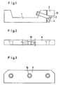
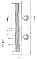
- the reference numeral 1 denotes a beam support, to which a plurality of strip-shaped segments 2 are assigned in its longitudinal direction, which are connected to the beam support 1 by screws. Only one of these screws can be seen in FIG. 1 and has been designated with the reference number 3.
- the Damping element 4 is intended to dampen vibrations and can be made of plastic or another metallic material than the beam support 1 and the segments 2, both of which are forged or rolled from steel.
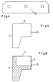
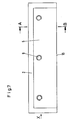
- Each segment 2 has a recess 5 which is approximately square or rectangular in cross section on its upper side.
- a plurality of sheet-like or sheet-like bodies are arranged, specifically an upper cover sheet 6 and a plurality of sheet-shaped items of equal size located below it Intermediate layers 7.
- the number of intermediate layers 7 can be greater or less than nine.
- the thickness of the intermediate layers 7 is considerably smaller than the thickness of the cover plate 6 and can only be about 1/10 to 1/5 of the cover plate 6.
- Both the cover plate 6 and the intermediate layers 7 are made of steel in the illustrated embodiments, but can also be made of different materials, for example aluminum, copper or plastic.
- cover plate 6 The entire package of cover plate 6 and intermediate layers 7 thus formed is held by a plurality of screws 8 (FIG. 8) which are screwed into threaded through bores 9.
- the cover plate 6 has depressions 10, in which the screw heads are each arranged flush with the upper edge 11 of the segments 2.
- a lubricating layer 12 is formed as a depot between the intermediate layers 7.
- the lubricant oozes out of this depot to the braking surface 13 and thereby prevents the unpleasant squeaking and screeching across all speed ranges of the railway wagons.
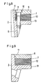
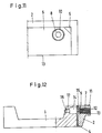
- the beam carrier 1 is assigned a depot chamber 14 for the lubricant, which is connected to the spaces between the intermediate layers 7 via a channel 15 and an extension 16.
- a filling channel 17 is connected to the depot chamber 14, in which a screw 18 is adjustably arranged in order to press the lubricant to the braking surface 13.
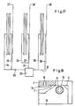
- a lubricant pump 19 is provided, which is connected via a line 20 and a connection fitting 21 to a channel 22, which optionally opens into a depot chamber 14, which in turn extends via the extension 16 to the spaces between the intermediate layers 7 is connected, thereby promoting lubricant to the braking surface 13.
- the lubricant pump 19 can also be connected to a plurality of depot chambers, which delivers lubricant to various braking surfaces, for example to a number of further bar track brakes, via a plurality of lines (not shown). It is also possible to connect a plurality of pumps 19 in parallel, which deliver the lubricant to the different braking surfaces 13.
- the intermediate layer 7 is assigned a plurality of depots 23 in the form of a lattice-like structure in which the lubricant is located.
- This can be a sieve-like or otherwise designed sheet with which the lubricant is assigned.
- a sieve-like body 24 is provided for storing the lubricant
- one or more intermediate layers are provided with corrugations 25 which also serve as depots for the lubricant. All the depots, corrugations and sieve-like formations are connected to the intermediate spaces of the intermediate layers 7 and thus to the braking surface 13, so that lubricant can reach the braking surface 13 from here.
- a pump 26 is assigned a plurality - in the present case three - beam track brakes 27, 28 and 29, the depot chambers of which are directed to the relevant ones via lines 30, 31 and 32 and branch lines 34, 35, 36, 37, 38 and 39 Lubricant chambers or depots and thus also connected to the braking surfaces 13 (not shown).
- the pump 26 can be controlled according to a certain program or depending on the braking frequency of the wagons and then deliver suitable lubricant to the braking surfaces 13 so that they remain lubricated continuously.
Landscapes
- Engineering & Computer Science (AREA)
- Mechanical Engineering (AREA)
- Braking Arrangements (AREA)
Abstract
Description
Die Erfindung bezieht sich auf eine Balkengleisbremse zum Abbremsen von Eisenbahnwaggons mit jeweils zwei beidseitig jeder Fahrschiene eines Gleises liegenden, oder aber mit zwei beidseitig einer Fahrschiene befindlichen Balken, die auf ihrer dem Waggonrad zugekehrten Seite eine oder mehrere langgestreckte Aussparungen zum Aufnehmen mindestens eines leistenförmigen Segments aufweisen, der auswechselbar in der betreffenden Aussparung angeordnet ist, wobei in dem betreffenden Segment an der dem Waggonrad zugekehrten Seite wenigstens eine Aussparung angeordnet ist, in der ein Deckblech und mehrere Zwischenlagen sandwichartig und aufeinanderliegend auswechselbar und z. B. durch Schrauben an dem Segment gehalten sind und die Segmente mit Hilfe eines Schmiermittels an ihrer dem Waggonrad zugekehrten Seite gleitfähig zu machen sind.The invention relates to a bar track brake for braking railway wagons, each with two bars on either side of a rail, or with two bars on both sides of a rail, which have on their side facing the wagon wheel one or more elongated recesses for receiving at least one strip-shaped segment , which is arranged interchangeably in the relevant recess, with at least one recess being arranged in the relevant segment on the side facing the wagon wheel, in which a cover plate and a plurality of intermediate layers are interchangeable and interchangeable and z. B. are held by screws on the segment and the segments are to be made slidable with the help of a lubricant on their side facing the wagon wheel.
Bei allgemein bekannten Rangieranlagen in Flachbahnhöfen wird der zu zerlegende Zug von einer Abdrücklok über einen Ablaufberg gedrückt. Hinter dem Ablaufberg erfolgt eine Abstandsbremsung der ablaufenden Wagen durch Balkengleisbremsen als Talbremsen. Die Einlaufgeschwindigkeit beträgt etwa 6 bis 8 m/s. Eine weitere Bremsstaffel befindet sich am Beginn der Richtungsgleise. Hier beträgt die Einlaufgeschwindigkeit etwa 4,5 m/s. Die Wagen werden auf etwa 1,5 m/s abgebremst.In generally known marshalling yards in flat train stations, the train to be dismantled is pushed by a push-off locomotive over a discharge hill. Behind the drain mountain, the wagons running are braked at a distance using beam track brakes as valley brakes. The entry speed is about 6 to 8 m / s. Another brake relay is at the beginning of the direction tracks. Here the entry speed is about 4.5 m / s. The cars are braked to about 1.5 m / s.
Es ist aber auch bekannt, die Einfahrgleise im Gefälle zu verlegen, so daß der Zug zunächst durch Festhaltebremsen gehalten ist. Werden diese Festhaltebremsen gelöst, so setzen sich die einzelnen Wagen infolge der Schwerkraft in Bewegung. Durch Balkengleisbremsen im Zulauf wird der Ablauf so geregelt, daß die Zulaufgeschwindigkeit über den Ablaufberg etwa der üblichen Abdrückgeschwindigkeit von etwa 1,5 m/s entspricht. Zur Vereinfachung des Sprachgebrauch bezeichnet man diese Bremsen auch als "Zulaufbremsen".But it is also known to lay the entry tracks on a slope, so that the train is initially held by parking brakes. If these parking brakes are released, the individual carriages start to move due to gravity. The process is regulated by bar track brakes in the inlet so that the inlet speed via the outlet hill corresponds approximately to the usual pulling speed of approximately 1.5 m / s. To simplify the use of language, these brakes are also referred to as "feed brakes".
Besonders bei Zulaufbremsen treten während des Bremsvorganges lang anhaltende Kreischgeräusche auf. Die Spitzenwerte betragen bis zu 117 dB (A). Eine Geräuschminderung hat man durch sogenannte Segmentbalkenbremsen erzielt (vergleiche ETR (27), 10-1978, S. 667-670; US-A-3,874,298). Die Segmentbremsbalken bestehen aus einem durchgehend gewalzten Bremsträger, an dessen Bremsflächen über die gesamte Länge einzelne Stahlsegmente angeschraubt sind. Diese Segmente sind etwa 400 mm lang und können mit einer 5 mm dicken Dämpfungsplatte vom eigentlichen Bremsträger isoliert sein.Long-lasting screeching noises occur in particular with intake brakes during the braking process. The peak values are up to 117 dB (A). Noise reduction has been achieved by so-called segmented bar brakes (see ETR (27), 10-1978, pp. 667-670; US-A-3,874,298). The segment brake beams consist of a continuously rolled brake carrier, on the braking surfaces of which individual steel segments are screwed over the entire length. These segments are about 400 mm long and can be isolated from the actual brake carrier with a 5 mm thick damping plate.
Eine Balkengleisbremse gemäß dem Gattungsbegriff des Patentanspruches 1 dieser Patentanmeldung ist durch die EP-A-0011317 vorbekannt, bei welcher die Segmente sandwichartig aufgebaut und aus einzelnen horizontal aufeinanderliegenden Platten gebildet sind, die aus unterschiedlichen Werkstoffen bestehen. Dieses so gebildete "Sandwichpaket" als Segment ist durch mehrere Schrauben mit einen aus Stahl bestehenden Bremsträger verbunden. Dieser Segmentbremsbalken verschleißt relativ schnell und besitzt nur einen engen Einsatzbereich bei Zulaufbremsen. Liegt die Einlaufgeschwindigkeit über 2 m/s, sind solche Bremsbacken nicht einsetzbar.A bar track brake according to the preamble of
Zwar wird in der EP-A-0011317 bereits vorgeschlagen, die Segmente der äußeren Balken mit Hilfe eines Schmiermittels gleitfähig zu machen, jedoch kann dies nur bei Begehungen von Fall zu Fall geschehen. Offensichtlich ist dabei daran gedacht worden, die Segmente mit einem Schmiermittel einzupinseln, was jedoch personalaufwendig und demgemäß kostenträchtig ist.It is already proposed in EP-A-0011317 to make the segments of the outer beams slidable with the aid of a lubricant, but this can only be done on a case-by-case basis. It has obviously been thought of brushing the segments with a lubricant, but this is labor-intensive and therefore costly.
Der Erfindung liegt die Aufgabe zugrunde, eine Balkengleisbremse gemäß dem Oberbegriff des Patentanspruches 1 dahingehend zu verbessern, daß die unangenehmen Kreisch-und Quietschgeräusche bei allen in der Praxis vorkommenden Geschwindigkeiten praktisch nicht mehr auftreten können.The invention has for its object to improve a bar track brake according to the preamble of
Ausgehend von einer Balkengleisbremse gemäß dem Oberbegriff des Patentanspruches 1 wird diese Aufgabe durch die kennzeichnenden Merkmale dieses Patentanspruches gelöst. Vorteilhafte Weiterbildungen des Erfindungsgegenstandes sind den Unteransprüchen zu entnehmen.Starting from a bar track brake according to the preamble of
Bei der erfindungsgemäß ausgebildeten Balkengleisbremse ist dem betreffenden Segment eine Schmiermittelvorrichtung zugeordnet, die das Schmiermittel verbrauchsabhängig an die dem Waggonrad zugekehrte Bremsfläche abgibt. Dadurch wird es möglich, die Bremsflächen der Segmente auch automatisch zu schmieren, so daß die unangenehmen Kreisch- und Quietschgeräusche auch bei Geschwindigkeiten unter 2 m/s, z. B. bei 1,5 m/s, nicht mehr auftreten können.In the beam track brake designed according to the invention, a lubricant device is assigned to the segment in question, which, depending on consumption, delivers the lubricant to the braking surface facing the wagon wheel. This makes it possible to automatically lubricate the braking surfaces of the segments, so that the unpleasant screeching and squeaking noises even at speeds below 2 m / s, for. B. at 1.5 m / s, can no longer occur.
Bei Anwendung einer erfindungsgemäß ausgebildeten Balkengleisbremse hat man es somit in der Hand, nur dann die Bremsflächen der Segmente zu schmieren, wenn tatsächlich ein Bremsvorgang eintritt. Man braucht somit keineswegs von vornherein Schmiermittel, z. B. Pasten oder Fette, dick auf die Bremsflächen aufzutragen, in der Hoffnung, daß sie sich über eine längere Betriebsdauer hier halten würden. Bei einer erfindungsgemäßen Balkengleisbremse tritt nur dann ein Schmiermittelverbrauch auf, wenn das Schmiermittel tatsächlich während des Bremsvorganges benötigt wird. Dadurch wird auch die Umwelt geschont, da beim unkontrollierten Schmieren der Segmente Öle und Fette in den Untergrund versickern und dadurch das Grundwasser schädigen könnten.When using a bar track brake designed according to the invention, it is therefore in your hand to lubricate the braking surfaces of the segments only when a braking process actually occurs. So you don't need lubricants from the outset, e.g. B. pastes or fats, thick to apply to the braking surfaces, in the hope that they would stay here for a longer period of time. In a bar track brake according to the invention, lubricant consumption only occurs when the lubricant is actually needed during the braking process. This also protects the environment, since oils and greases seep into the subsoil if the segments are lubricated in an uncontrolled manner and could damage the groundwater.
Bei einer erfindungsgemäß ausgebildeten Balkengleisbremse ist somit eine "Depotbildung" mit Schmiermittel in der Balkengleisbremse selbst möglich, wobei aus dem Schmiermitteldepot Schmiermittel nach und nach an die Bremsflächen der Segmente gesteuert abgegeben werden kann.In the case of a bar track brake designed in accordance with the invention, it is thus possible to "build up a deposit" with lubricant in the bar track brake itself, it being possible for lubricant to be gradually released from the lubricant depot to the braking surfaces of the segments.
Eine erfindungsgemäß ausgebildete Balkengleisbremse kann dadurch über alle in der Praxis auftretenden Geschwindigkeitsbereiche die unangenehmen Quietsch- und Kreischgeräusche beim Abbremsen von Eisenbahnwaggons sicher vermeiden.A bar track brake designed according to the invention can thus reliably avoid the unpleasant squeaking and screeching noises when braking down railroad cars over all speed ranges that occur in practice.
Anhand der Zeichnung sind Ausführungsbeispiele der Erfindung ― teils schematisch ― eingehend veranschaulicht. Es zeigen:
- Fig. 1
- einen Querschnitt durch eine Balkengleisbremse mit einem Segmentbremsbalken;
- Fig. 2
- ein Deckblech, teils in der Seitenansicht, teils im Schnitt;
- Fig. 3
- die Draufsicht zu Fig. 2;
- Fig. 4
- eine Zwischenlage, gleichfalls in der Draufsicht;
- Fig. 5
- ein Segment in Ansichtrichtung des Pfeiles X der Fig. 7;
- Fig. 6
- den Schnitt nach der Linie A-B der Fig. 7;
- Fig. 7
- die Draufsicht auf ein Segment gemäß Fig. 5 oder 6;
- Fig. 8
- ein Segment mit mehreren Zwischenlagen und einem Deckblech, teils im Schnitt und teils in der Ansicht in Richtung des Pfeiles Y der Fig. 10;
- Fig. 9
- den Schnitt nach der Linie E-F der Fig. 10;
- Fig. 10
- eine Seitenansicht zu Fig. 9;
- Fig. 11
- die teilweise Draufsicht auf ein Bremssegment, teils abgebrochen dargestellt;
- Fig. 12
- einen Bremsbalken, teils in der Seitenansicht, teils im Schnitt mit einer Schmiermitteldepotkammer;
- Fig. 13
- eine weitere Ausführungsform der Balkengleisbremse und zwar mit einer Schmiermittelpumpe;
- Fig. 14
- eine weitere Ausführungsform der Gleisbremse, teils in der Ansicht, teils herausgebrochen dargestellt;
- Fig. 15
- eine weitere Ausführungsform mit einem siebartigen Körper;
- Fig. 16
- eine andere Ausführungsform mit Riefelungen und/oder Ausstanzungen;
- Fig. 17
- eine weitere Ausführungsform in schematischer Draufsicht und
- Fig. 18
- eine weitere Ausführungsform der Gleisbremse.
Exemplary embodiments of the invention - partly schematically - are illustrated in detail with the aid of the drawing. Show it:
- Fig. 1
- a cross section through a bar track brake with a segment brake beam;
- Fig. 2
- a cover plate, partly in side view, partly in section;
- Fig. 3
- the top view of Fig. 2;
- Fig. 4
- an intermediate layer, also in plan view;
- Fig. 5
- a segment in the direction of arrow X of FIG. 7;
- Fig. 6
- the section along the line AB of Fig. 7;
- Fig. 7
- the top view of a segment of FIG 5 or 6.
- Fig. 8
- a segment with several intermediate layers and a cover plate, partly in section and partly in the view in the direction of arrow Y of FIG. 10;
- Fig. 9
- the section along the line EF of Fig. 10;
- Fig. 10
- a side view of Fig. 9;
- Fig. 11
- the partial top view of a brake segment, shown partially broken off;
- Fig. 12
- a brake beam, partly in side view, partly in section with a lubricant depot chamber;
- Fig. 13
- a further embodiment of the bar track brake with a lubricant pump;
- Fig. 14
- a further embodiment of the track brake, partly shown in the view, partly broken out;
- Fig. 15
- a further embodiment with a sieve-like body;
- Fig. 16
- another embodiment with corrugations and / or punched-outs;
- Fig. 17
- a further embodiment in a schematic plan view and
- Fig. 18
- another embodiment of the track brake.
Mit dem Bezugszeichen 1 ist ein Balkenträger bezeichnet, dem in seiner Längsrichtung mehrere leistenförmige Segmente 2 zugeordnet sind, die durch Schrauben mit dem Balkenträger 1 verbunden sind. Von diesen Schrauben ist lediglich eine in Fig. 1 ersichtlich und mit dem Bezugszeichen 3 bezeichnet worden. In Längsrichtung des Balkenträgers 1 sind mehrere solcher Segmente 2 in Flucht hintereinander angeordnet und durch ein plattenförmiges Dämpfungselement 4 gegen den Balkenträger 1 abgestützt. Das Dämpfungselement 4 soll Schwingungen dämpfen und kann aus Kunststoff oder einem anderen metallischen Werkstoff bestehen als der Balkenträger 1 und die Segmente 2, die beide aus Stahl geschmiedet bzw. gewalzt sind.The
Jedes Segment 2 weist an seiner Oberseite eine im Querschnitt etwa quadratische oder rechteckförmige Aussparung 5 auf. In dieser Aussparung 5 sind mehrere schichtförmige oder blechartige Körper angeordnet, und zwar ein oberes Deckblech 6 und mehrere darunter befindliche, gleich große, blechförmige Zwischenlagen 7. Aus den Fig. 8 und 9 ist ersichtlich, daß bei diesen Ausführungsformen neun Zwischenlagen 7 vorgesehen sind. Die Anzahl Zwischenlagen 7 kann größer oder kleiner als neun sein. Die Dicke der Zwischenlagen 7 ist erheblich kleiner als die Dicke des Deckbleches 6 und kann etwa nur 1/10 bis 1/5 des Deckbleches 6 betragen. Sowohl das Deckblech 6 als auch die Zwischenlagen 7 sind bei den dargestellten Ausführungsformen aus Stahl hergestellt, können aber auch aus unterschiedlichen Werkstoffen, beispielsweise aus Aluminium, Kupfer oder Kunststoff, hergestellt sein.Each
Das gesamte so gebildete Paket aus Deckblech 6 und Zwischenlagen 7 wird durch mehrere Schrauben 8 (Fig. 8) gehalten, die in mit Gewinde versehene Durchgangsbohrungen 9 eingeschraubt sind. Das Deckblech 6 weist dazu Einsenkungen 10 auf, in denen die Schraubköpfe jeweils bündig mit der Oberkante 11 der Segmente 2 angeordnet sind.The entire package of
Bei den aus den Fig. 1 bis 9 ersichtlichen Ausführungsformen ist zwischen den Zwischenlagen 7 jeweils eine Schmierschicht 12 als Depot gebildet. Aus diesem Depot quillt das Schmiermittel beim Abbremsen eines Waggonrades zur Bremsfläche 13 heraus und verhindert dadurch das unangenehme Quietschen und Kreischen über alle Geschwindigkeitsbereiche der Eisenbahnwagen.In the embodiments shown in FIGS. 1 to 9, a
Bei der aus der Fig. 12 ersichtlichen Ausführungsform ist dem Balkenträger 1 eine Depotkammer 14 für den Schmierstoff zugeordnet, die über einen Kanal 15 und einer Erweiterung 16 an die Zwischenräume zwischen den Zwischenlagen 7 angeschlossen ist. An die Depotkammer 14 ist ein Einfüllkanal 17 angeschlossen, in dem eine Schraube 18 verstellbar angeordnet ist, um das Schmiermittel zu der Bremsfläche 13 zu drücken.In the embodiment shown in FIG. 12, the
Bei der Ausführungsform nach Fig. 13 ist eine Schmiermittelpumpe 19 vorgesehen, die über eine Leitung 20 und eine Anschlußarmatur 21 an einen Kanal 22 angeschlossen ist, der gegebenfalls in eine Depotkammer 14 ausmündet, die wiederum über die Erweiterung 16 an die Zwischenräume zwischen den Zwischenlagen 7 angeschlossen ist, und dadurch Schmiermittel zur Bremsfläche 13 fördert.In the embodiment according to FIG. 13, a
Die Schmiermittelpumpe 19 kann auch an mehrere Depotkammern angeschlossen werden, die über mehrere nicht dargestellte Leitungen Schmiermittel zu verschiedenen Bremsflächen, beispielsweise zu einer Anzahl weiterer Balkengleisbremsen fördert. Es ist außerdem möglich, mehrere Pumpen 19 parallel zu schalten, die den Schmierstoff zu den verschiedenen Bremsflächen 13 fördern.The
Bei der Ausführungsform nach Fig. 14 sind der Zwischenschicht 7 mehrere Depots 23 in Form eines gitterartigen Gebildes zugeordnet, in denen sich der Schmierstoff befindet. Es kann sich hierbei um ein siebartiges oder sonst wie gestaltetes Blech handeln, dem der Schmierstoff zugeordnet wird.In the embodiment according to FIG. 14, the
Bei der Ausführungsform nach Fig. 15 ist ein siebartiger Körper 24 zum Speichern des Schmierstoffes vorgesehen, während bei der Ausführungsform nach Fig. 16 eine oder mehrere Zwischenlagen mit Riefelungen 25 versehen sind, die ebenfalls als Depots für den Schmierstoff dienen. Alle die Depots, Riefelungen und siebartigen Ausformungen sind an die Zwischenräume der Zwischenlagen 7 und damit an die Bremsfläche 13 angeschlossen, so das von hier aus Schmierstoff zur Bremsfläche 13 gelangen kann.In the embodiment according to FIG. 15, a sieve-
Bei der Ausführungsform nach Fig. 17 ist einer Pumpe 26 eine Mehrzahl ― vorliegend drei ― Balkengleisbremsen 27, 28 und 29 zugeordnet, deren Depotkammern über Leitungen 30, 31 und 32 sowie Zweigleitungen 34, 35, 36, 37, 38 und 39 an die betreffenden Schmiermittelkammern oder Depots und damit auch an die Bremsflächen 13 (nicht dargestellt) angeschlossen sind. Die Pumpe 26 kann nach einem bestimmten Programm oder aber in Abhängigkeit der Bremsfrequenz der Waggons gesteuert sein und dann geeignetes Schmiermittel zu den Bremsflächen 13 fördern, so daß diese dauernd geschmiert bleiben.In the embodiment according to FIG. 17, a
Bei der Ausführungsform nach Fig. 18 wird das Schmiermittel ― ähnlich wie bei der Ausführungsform nach Fig. 12 ― aus einer dort nicht dargestellten Depotkammer 14 über einen Kanal 15 auf ein Depot 40 verteilt, von wo aus sich das Schmiermittel über die Zwischenlagen 7 und deren Zwischenräume zur Bremsfläche 13 hinverteilt.
- 1
- Balkenträger
- 2
- Segment
- 3
- Schraube
- 4
- Dämpfungselement
- 5
- Aussparung
- 6
- Deckblech
- 7
- Zwischenlage
- 8
- Schraube
- 9
- Durchgangsbohrung
- 10
- Einsenkung
- 11
- Oberkante
- 12
- Schmierschicht
- 13
- Bremsfläche
- 14
- Depotkammer
- 15
- Kanal
- 16
- Erweiterung
- 17
- Einfallkanal
- 18
- Schraube
- 19
- Schmiermittelpumpe
- 20
- Leitung
- 21
- Anschlußarmatur
- 22
- Kanal
- 23
- Depot
- 24
- siebartiger Körper
- 25
- Riefelungen
- 26
- Pumpe
- 27
- Balkengleisbremsen
- 28
- "
- 29
- "
- 30
- Leitung
- 31
- "
- 32
- "
- 33
- 34
- Zweigleitungen
- 35
- "
- 36
- "
- 37
- "
- 38
- "
- 39
- "
- 40
- Depot
In the embodiment according to FIG. 18, the lubricant - similar to the embodiment according to FIG. 12 - is distributed from a
- 1
- Beam support
- 2nd
- segment
- 3rd
- screw
- 4th
- Damping element
- 5
- Recess
- 6
- Cover plate
- 7
- Liner
- 8th
- screw
- 9
- Through hole
- 10th
- Sinking
- 11
- Top edge
- 12th
- Smear layer
- 13
- Braking surface
- 14
- Depository
- 15
- channel
- 16
- extension
- 17th
- Incident channel
- 18th
- screw
- 19th
- Lubricant pump
- 20th
- management
- 21st
- Connection fitting
- 22
- channel
- 23
- depot
- 24th
- sieve-like body
- 25th
- Corrugations
- 26
- pump
- 27th
- Beam track brakes
- 28
- "
- 29
- "
- 30th
- management
- 31
- "
- 32
- "
- 33
- 34
- Branch lines
- 35
- "
- 36
- "
- 37
- "
- 38
- "
- 39
- "
- 40
- depot
Claims (4)
Priority Applications (1)
| Application Number | Priority Date | Filing Date | Title |
|---|---|---|---|
| AT88114489T ATE66878T1 (en) | 1987-10-29 | 1988-09-05 | BEAM TRACK BRAKE FOR BRAKING RAILWAY CARS. |
Applications Claiming Priority (2)
| Application Number | Priority Date | Filing Date | Title |
|---|---|---|---|
| DE3736580 | 1987-10-29 | ||
| DE19873736580 DE3736580A1 (en) | 1987-10-29 | 1987-10-29 | BEAM TRACK BRAKE FOR BRAKING RAILWAYS |
Publications (2)
| Publication Number | Publication Date |
|---|---|
| EP0313771A1 EP0313771A1 (en) | 1989-05-03 |
| EP0313771B1 true EP0313771B1 (en) | 1991-09-04 |
Family
ID=6339297
Family Applications (1)
| Application Number | Title | Priority Date | Filing Date |
|---|---|---|---|
| EP88114489A Expired - Lifetime EP0313771B1 (en) | 1987-10-29 | 1988-09-05 | Beam type brake for decelerating railroad cars |
Country Status (4)
| Country | Link |
|---|---|
| EP (1) | EP0313771B1 (en) |
| AT (1) | ATE66878T1 (en) |
| DE (1) | DE3736580A1 (en) |
| ES (1) | ES2023991B3 (en) |
Families Citing this family (6)
| Publication number | Priority date | Publication date | Assignee | Title |
|---|---|---|---|---|
| DE3930332C2 (en) * | 1989-09-11 | 1997-08-14 | Siemens Ag | Brake beam for bar track brakes with segmented wear elements |
| SI20202A (en) * | 1999-03-10 | 2000-10-31 | Bojan Pav�nik | Noise dampening device for rail breaks |
| DE10240668A1 (en) * | 2002-09-04 | 2004-03-18 | Cww-Gerko Akustik Gmbh | Bar retarder |
| DE102005054832B3 (en) * | 2005-11-15 | 2007-08-23 | ThyssenKrupp Präzisionsschmide GmbH | Rail brake for rail vehicles |
| DE102011115089A1 (en) * | 2011-10-07 | 2013-04-11 | Sona Blw Präzisionsschmiede Gmbh | Rail brake for rail vehicles |
| SI25377A (en) * | 2017-02-07 | 2018-08-31 | Bojan PAVČNIK | Lamella of the rail element, preferably the rail brakes and the process of its use |
Family Cites Families (8)
| Publication number | Priority date | Publication date | Assignee | Title |
|---|---|---|---|---|
| US3874298A (en) * | 1972-11-01 | 1975-04-01 | Gen Signal Corp | Noise suppression system for car retarders |
| GB1482999A (en) * | 1973-12-15 | 1977-08-17 | Thyssen Huette Ag | Brake beams for beam-type rail brakes |
| GB1479595A (en) * | 1974-10-29 | 1977-07-13 | Swindells J | Pumps and lubricating devices including pumps |
| US4003451A (en) * | 1975-06-30 | 1977-01-18 | Qiv Incorporated | Low noise brake shoe for track retarder |
| DE2555722B1 (en) * | 1975-12-11 | 1977-05-18 | Andreas Radermacher | Rail mounted wheel activated railway track lubricator - has delayed action return on pump piston and cylinder spring support |
| US4088078A (en) * | 1976-06-04 | 1978-05-09 | Westinghouse Air Brake Company | Lubricating apparatus for reducing squeal noise of a railroad car wheel when passing through a car retarder |
| CH634514A5 (en) * | 1978-11-16 | 1983-02-15 | Schweizerische Bundesbahnen | BEAM TRACK BRAKE. |
| DE7930282U1 (en) * | 1979-10-25 | 1980-04-10 | Radermacher, Andreas, 5376 Nettersheim | DRIVE RAIL WITH HOLES FOR THE SUPPLY OF LUBRICANTS |
-
1987
- 1987-10-29 DE DE19873736580 patent/DE3736580A1/en active Granted
-
1988
- 1988-09-05 EP EP88114489A patent/EP0313771B1/en not_active Expired - Lifetime
- 1988-09-05 AT AT88114489T patent/ATE66878T1/en active
- 1988-09-05 ES ES88114489T patent/ES2023991B3/en not_active Expired - Lifetime
Also Published As
| Publication number | Publication date |
|---|---|
| DE3736580C2 (en) | 1990-05-17 |
| ATE66878T1 (en) | 1991-09-15 |
| ES2023991B3 (en) | 1992-02-16 |
| DE3736580A1 (en) | 1989-05-18 |
| EP0313771A1 (en) | 1989-05-03 |
Similar Documents
| Publication | Publication Date | Title |
|---|---|---|
| DE2816561C3 (en) | System of rail wheel and track for rail vehicles | |
| EP2190624B1 (en) | Wheelset press | |
| EP2552761B1 (en) | Rail vehicle with variable axel geometry | |
| EP0313771B1 (en) | Beam type brake for decelerating railroad cars | |
| EP2339197B1 (en) | Disc brake, brake calliper of such a brake and method for producing such a brake calliper | |
| EP1834042B1 (en) | Machine for renovation of a track | |
| AT410808B (en) | Ballastless superstructure for rail-bound traffic | |
| DE102011115089A1 (en) | Rail brake for rail vehicles | |
| DE102017122023A1 (en) | Underfloor wheelset machine, in particular underfloor wheel lathe with adjustable track width | |
| EP1572386A1 (en) | Rolling mill comprising means for exchanging the rolls | |
| DE202010018220U1 (en) | Lubricating device for a Radlenkervorrichtung | |
| DE2608372C2 (en) | Mobile track-laying machine for compacting the ballast beneath the sleepers of a track | |
| DE3930332A1 (en) | Beam for brake for railway vehicle - is formed from U=shaped steel section with welded transverse ribs | |
| DE102013108864A1 (en) | Motor vehicle pallet and production system and method for producing a motor vehicle pallet | |
| EP0752341A1 (en) | Vehicle | |
| EP0843632B1 (en) | Braking arrangement with a curved sorting siding | |
| DE604350C (en) | ||
| AT140886B (en) | Railway wheel or the like. | |
| DE102004060804A1 (en) | Rail lubricating and moistening device for e.g. trolley-car, has rail with grooving and head rails, where groove of grooving rail serves as lubricant reservoir is filled with fluid up to preset height over inlet guide in controlled manner | |
| EP0252153B1 (en) | Method and device for controlling the speed of rail vehicles | |
| DE202017105763U1 (en) | Underfloor wheel lathe with adjustable gauge | |
| DE2340779A1 (en) | HYDRAULIC BRAKE DEVICE FOR RAIL VEHICLES | |
| DE1605382C (en) | Track braking device for braking rail vehicles | |
| DE102004005840B4 (en) | Equipment is for laying rails and sleepers for mobile cranes and involves frame with at least two bearers which extend next to rail involved | |
| DD212544A1 (en) | RAIL-CONTAINED TRANSPORT CAR FOR SCHUETTGUETER |
Legal Events
| Date | Code | Title | Description |
|---|---|---|---|
| PUAI | Public reference made under article 153(3) epc to a published international application that has entered the european phase |
Free format text: ORIGINAL CODE: 0009012 |
|
| 17P | Request for examination filed |
Effective date: 19880920 |
|
| AK | Designated contracting states |
Kind code of ref document: A1 Designated state(s): AT BE CH ES FR GB GR IT LI LU NL SE |
|
| 17Q | First examination report despatched |
Effective date: 19900213 |
|
| GRAA | (expected) grant |
Free format text: ORIGINAL CODE: 0009210 |
|
| AK | Designated contracting states |
Kind code of ref document: B1 Designated state(s): AT BE CH ES FR GB GR IT LI LU NL SE |
|
| PG25 | Lapsed in a contracting state [announced via postgrant information from national office to epo] |
Ref country code: GR Free format text: LAPSE BECAUSE OF FAILURE TO SUBMIT A TRANSLATION OF THE DESCRIPTION OR TO PAY THE FEE WITHIN THE PRESCRIBED TIME-LIMIT Effective date: 19910904 |
|
| REF | Corresponds to: |
Ref document number: 66878 Country of ref document: AT Date of ref document: 19910915 Kind code of ref document: T |
|
| ITF | It: translation for a ep patent filed |
Owner name: BARZANO' E ZANARDO MILANO S.P.A. |
|
| GBT | Gb: translation of ep patent filed (gb section 77(6)(a)/1977) | ||
| ET | Fr: translation filed | ||
| REG | Reference to a national code |
Ref country code: ES Ref legal event code: FG2A Ref document number: 2023991 Country of ref document: ES Kind code of ref document: B3 |
|
| PLBE | No opposition filed within time limit |
Free format text: ORIGINAL CODE: 0009261 |
|
| STAA | Information on the status of an ep patent application or granted ep patent |
Free format text: STATUS: NO OPPOSITION FILED WITHIN TIME LIMIT |
|
| 26N | No opposition filed | ||
| EPTA | Lu: last paid annual fee | ||
| EAL | Se: european patent in force in sweden |
Ref document number: 88114489.3 |
|
| PGFP | Annual fee paid to national office [announced via postgrant information from national office to epo] |
Ref country code: GB Payment date: 19950825 Year of fee payment: 8 |
|
| PGFP | Annual fee paid to national office [announced via postgrant information from national office to epo] |
Ref country code: FR Payment date: 19950911 Year of fee payment: 8 |
|
| PGFP | Annual fee paid to national office [announced via postgrant information from national office to epo] |
Ref country code: CH Payment date: 19950913 Year of fee payment: 8 |
|
| PGFP | Annual fee paid to national office [announced via postgrant information from national office to epo] |
Ref country code: AT Payment date: 19950914 Year of fee payment: 8 |
|
| PGFP | Annual fee paid to national office [announced via postgrant information from national office to epo] |
Ref country code: SE Payment date: 19950918 Year of fee payment: 8 |
|
| PGFP | Annual fee paid to national office [announced via postgrant information from national office to epo] |
Ref country code: NL Payment date: 19950922 Year of fee payment: 8 |
|
| PGFP | Annual fee paid to national office [announced via postgrant information from national office to epo] |
Ref country code: ES Payment date: 19950928 Year of fee payment: 8 |
|
| PGFP | Annual fee paid to national office [announced via postgrant information from national office to epo] |
Ref country code: LU Payment date: 19951001 Year of fee payment: 8 |
|
| PGFP | Annual fee paid to national office [announced via postgrant information from national office to epo] |
Ref country code: BE Payment date: 19951011 Year of fee payment: 8 |
|
| PG25 | Lapsed in a contracting state [announced via postgrant information from national office to epo] |
Ref country code: LU Free format text: LAPSE BECAUSE OF NON-PAYMENT OF DUE FEES Effective date: 19960905 Ref country code: GB Effective date: 19960905 Ref country code: AT Effective date: 19960905 |
|
| PG25 | Lapsed in a contracting state [announced via postgrant information from national office to epo] |
Ref country code: SE Effective date: 19960906 Ref country code: ES Free format text: LAPSE BECAUSE OF THE APPLICANT RENOUNCES Effective date: 19960906 |
|
| PG25 | Lapsed in a contracting state [announced via postgrant information from national office to epo] |
Ref country code: LI Effective date: 19960930 Ref country code: FR Effective date: 19960930 Ref country code: CH Effective date: 19960930 Ref country code: BE Effective date: 19960930 |
|
| BERE | Be: lapsed |
Owner name: THYSSEN INDUSTRIE A.G. UMFORMTECHNIK/BERGBAUTECHN Effective date: 19960930 |
|
| PG25 | Lapsed in a contracting state [announced via postgrant information from national office to epo] |
Ref country code: NL Effective date: 19970401 |
|
| GBPC | Gb: european patent ceased through non-payment of renewal fee |
Effective date: 19960905 |
|
| REG | Reference to a national code |
Ref country code: CH Ref legal event code: PL |
|
| NLV4 | Nl: lapsed or anulled due to non-payment of the annual fee |
Effective date: 19970401 |
|
| EUG | Se: european patent has lapsed |
Ref document number: 88114489.3 |
|
| REG | Reference to a national code |
Ref country code: FR Ref legal event code: ST |
|
| REG | Reference to a national code |
Ref country code: FR Ref legal event code: ST |
|
| REG | Reference to a national code |
Ref country code: ES Ref legal event code: FD2A Effective date: 19991007 |
|
| PG25 | Lapsed in a contracting state [announced via postgrant information from national office to epo] |
Ref country code: IT Free format text: LAPSE BECAUSE OF NON-PAYMENT OF DUE FEES;WARNING: LAPSES OF ITALIAN PATENTS WITH EFFECTIVE DATE BEFORE 2007 MAY HAVE OCCURRED AT ANY TIME BEFORE 2007. THE CORRECT EFFECTIVE DATE MAY BE DIFFERENT FROM THE ONE RECORDED. Effective date: 20050905 |