EP0313403A2 - Staubsaugermundstück - Google Patents
Staubsaugermundstück Download PDFInfo
- Publication number
- EP0313403A2 EP0313403A2 EP88309953A EP88309953A EP0313403A2 EP 0313403 A2 EP0313403 A2 EP 0313403A2 EP 88309953 A EP88309953 A EP 88309953A EP 88309953 A EP88309953 A EP 88309953A EP 0313403 A2 EP0313403 A2 EP 0313403A2
- Authority
- EP
- European Patent Office
- Prior art keywords
- projections
- floor nozzle
- web
- agitator
- rotor
- Prior art date
- Legal status (The legal status is an assumption and is not a legal conclusion. Google has not performed a legal analysis and makes no representation as to the accuracy of the status listed.)
- Granted
Links
Images

Classifications
-
- A—HUMAN NECESSITIES
- A47—FURNITURE; DOMESTIC ARTICLES OR APPLIANCES; COFFEE MILLS; SPICE MILLS; SUCTION CLEANERS IN GENERAL
- A47L—DOMESTIC WASHING OR CLEANING; SUCTION CLEANERS IN GENERAL
- A47L9/00—Details or accessories of suction cleaners, e.g. mechanical means for controlling the suction or for effecting pulsating action; Storing devices specially adapted to suction cleaners or parts thereof; Carrying-vehicles specially adapted for suction cleaners
- A47L9/02—Nozzles
- A47L9/04—Nozzles with driven brushes or agitators
- A47L9/0405—Driving means for the brushes or agitators
- A47L9/0416—Driving means for the brushes or agitators driven by fluid pressure, e.g. by means of an air turbine
-
- A—HUMAN NECESSITIES
- A47—FURNITURE; DOMESTIC ARTICLES OR APPLIANCES; COFFEE MILLS; SPICE MILLS; SUCTION CLEANERS IN GENERAL
- A47L—DOMESTIC WASHING OR CLEANING; SUCTION CLEANERS IN GENERAL
- A47L11/00—Machines for cleaning floors, carpets, furniture, walls, or wall coverings
- A47L11/32—Carpet-sweepers
- A47L11/33—Carpet-sweepers having means for storing dirt
-
- A—HUMAN NECESSITIES
- A47—FURNITURE; DOMESTIC ARTICLES OR APPLIANCES; COFFEE MILLS; SPICE MILLS; SUCTION CLEANERS IN GENERAL
- A47L—DOMESTIC WASHING OR CLEANING; SUCTION CLEANERS IN GENERAL
- A47L9/00—Details or accessories of suction cleaners, e.g. mechanical means for controlling the suction or for effecting pulsating action; Storing devices specially adapted to suction cleaners or parts thereof; Carrying-vehicles specially adapted for suction cleaners
- A47L9/02—Nozzles
- A47L9/04—Nozzles with driven brushes or agitators
- A47L9/0461—Dust-loosening tools, e.g. agitators, brushes
- A47L9/0466—Rotating tools
- A47L9/0477—Rolls
-
- A—HUMAN NECESSITIES
- A47—FURNITURE; DOMESTIC ARTICLES OR APPLIANCES; COFFEE MILLS; SPICE MILLS; SUCTION CLEANERS IN GENERAL
- A47L—DOMESTIC WASHING OR CLEANING; SUCTION CLEANERS IN GENERAL
- A47L9/00—Details or accessories of suction cleaners, e.g. mechanical means for controlling the suction or for effecting pulsating action; Storing devices specially adapted to suction cleaners or parts thereof; Carrying-vehicles specially adapted for suction cleaners
- A47L9/02—Nozzles
- A47L9/04—Nozzles with driven brushes or agitators
- A47L9/0461—Dust-loosening tools, e.g. agitators, brushes
- A47L9/0483—Reciprocating or oscillating tools, e.g. vibrators, agitators, beaters
Definitions
- the present invention relates to a floor nozzle having an agitator for use with a vacuum cleaner.
- Floor nozzles for use with vacuum cleaners have an agitator comprising a rotor with bristles attached to its circumferential surface.
- a rotor with bristles attached to its circumferential surface.
- the bristles on the rotating rotor rub the carpet to brush up dust particles which are then drawn into the floor nozzle under a vacuum developed by the vacuum cleaner.
- a floor nozzle for use with a vacuum cleaner includes a housing, an agitator rotatably disposed in the housing, the agitator comprising a rotor and at least one elongate web mounted on a circumferential surface of the rotor, the elongate web being made of a flexible material and having a plurality of projections on at least one of opposite surfaces thereof, and means disposed in the housing for rotating the agitator.
- the projections are configured to avoid the surface of the agitator becoming covered with waste thread or fibrous materials and may be in the form of teeth.
- the elongate web has smooth slanted surfaces respectively on opposite ends thereof to prevent tne opposite ends of the web from catching filamentary dust pieces such as hairs and waste threads.
- the rotor has at least one helical groove of a substantially T-shaped cross section defined longitudinally in the circumferential surface, the elongate web having on one edge thereof an anchor foot of a substantially T-shaped cross section, the anchor foot being inserted in the groove and having a plurality of longitudinally extending ridges held against an inner surface of the groove. Since the anchor foot is held against the inner surface of the groove only through the ridges providing a small area of contact, the flexible web can smoothly be inserted longitudinally into the groove from one open end thereof without being subjected to large frictional resistance and unwanted deformation. Therefore, the agitator can be assembled with ease and is of high quality.
- the rotor is extrusion-molded of a material of a low expansion ratio such as polystyrene.
- the rotor thus formed has a hard skin layer on its outer surface (including the inner surface of the T-shaped groove) for reducing frictional resistance which is presented to the insertion of the elongate web into the groove.
- the elongate web may include a first portion having the projections, and a second portion free therefrom and near the rotor, the first portion having a thickness different from that of the second portion.
- the projections may include a first group of projections and a second group of projections, the projections of the first group and the projections of the second group having different heights and being alternately positioned.
- the projections may be disposed on opposite surfaces of the elongate web and include a plurality of first projections on one of the opposite surfaces thereof and a plurality of second projections on the other opposite surfaces.
- the floor nozzle can effectively collect hairs, waste threads, and other filamentary dust pieces from a floor nozzle being cleaned, and can maintain a desired high dust-collecting capability.
- the agitator also has a long service life.
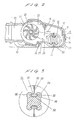
- Figs. 1 through 7 show a floor nozzle for use with a vacuum cleaner according to an embodiment of the present invention.
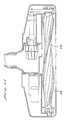
- the floor nozzle has a housing 7 comprising upper and lower casings 9, 10 joined to each other.
- the housing 7 has a suction chamber 12 defined in a front portion thereof and having a lower suction opening or port 11, and a turbine chamber 13 defined in a rear portion thereof.
- the turbine chamber 13 is separated from the suction chamber 12 by a partition 14.
- the housing 7 accommodates therein an agitator 16 disposed in and paral lel to the suction chamber 12 for rotation about its own horizontal axis.
- the agitator 16 is rotatably supported by a pair of opposite bearings 17 on laterally opposite side walls of the suction chamber 12.
- a fixed brush 18 is securely attached to the lower panel of the housing 7 behind the suction port 11 and extends parallel to the suction port 11.
- Wheels 19, 20 are rotatably mounted on the housing 7 at front and rear portions thereof for keeping the suction port 11 spaced a certain distance from a surface to be cleaned.
- a substantially semicylindrical suction joint 21 is angularly slidably supported in a rear portion of the turbine chamber 13 by a pair of laterally opposite shafts, the suction joint 21 having a rearwardly projecting mouth 15 from which a joint tube 22 extends rearwardly.
- a floor nozzle pipe 24 is rotatably mounted on the joint tube 22 with an O-ring 23 interposed therebetween. The floor nozzle pipe 24 is detachably connected to an extension pipe (not shown) which is coupled through a hose to the suction hole of a vacuum cleaner (not shown).
- a turbine 25 is rotatably disposed in the turbine chamber 13 with its outer circumference partly surrounded by the suction joint 21.
- the turbine 25 has an integral shaft 26 projecting laterally out of the turbine chamber coaxially through one of the shafts of the suction joint 21.
- the shaft 26 is rotatably supported in the nozzle housing 10 and has its projecting distal end operatively coupled to a pulley 28 on one end of the agitator 16 by means of an endless belt 27 near one of the bearings 17. Therefore, the agitator 16 can be rotated about its own axis by rotative power transmitted from the turbine 25 through the belt 27.
- the turbine 25 is displaced off the center of the turbine chamber 13 as it is viewed in plan toward the belt 27.
- the partition 14 has two vent holes 29, 30 defined therein.
- the vent hole 29 is positioned in confronting relation to the lower half of the turbine 25.
- the other vent hole 30 is positioned in directly confronting relation to the joint tube 22 of the suction joint 21, without facing the turbine 25.
- a switching lever 31 slidably mounted in the nozzle housing 10 has a shield plate 32 which can be laterally moved to selectively open and close the vent hole 30 in response to sliding movement of the switching lever 31.
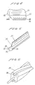
- the agitator 16 comprises an elongate rotor 34 with a pair of diametrically opposite elongate webs 35 mounted on the outer circumferential surface and extending helically in the longitudinal direction of the rotor 34. More specifically, as shown in Figs. 3 and 6, the rotor 34 has a pair of diametrically opposite helical grooves 36 of substantially T-shaped cross section defined in the outer circumferential surface, each groove 36 having open opposite ends.
- the elongate webs 35 have respective anchor feet 37 of substantially T-shaped cross section on one edge thereof which are snugly fitted respectively in the grooves 36. As shown in Figs.
- each of the anchor feet 37 has a plurality of longitudinally continuous ridges 38 held in contact with the inner surface of one of the grooves 36.
- the elongate webs 35 are made of a flexible material such as rubber or the like, and have a multiplicity of teeth 39 on at least one surface thereof (which will be a leading surface when the rotor 34 is rotated). As illustrated in Fig. 4, each of the opposite ends of each elongate web 35 has a smooth tapered or slanted surface 35a.
- the elongate webs 35 are in the form of elongate unitary strips rather than bristles, waste pieces of thread and other filamentary objects are prevented from getting entangled with the webs 35.
- the tapered or slanted surfaces 35a of the ends of the webs 35 prevent the web ends from being excessively flexed, i.e., allow them to become somewhat resilient, so that fibrous objects will not remain entangled with the ends of the webs 35 or will not easily be caught by the ends of the webs 35.
- the elongate webs 35 are inserted into the rotor 34 as follows:
- the T-shaped anchor foot 37 of each of the elongate webs 35 is longitudinally inserted into one of the T-shaped grooves 36 from one of the open ends thereof.
- the webs 35 which are made of a flexible material, elongate, and stretchable can smoothly be inserted into the respective helical grooves 36 while retaining their original shape. Accordingly, the elongate webs 35 can be installed in place in a reduced number of assembling steps and are stable in quality.
- the agitator 16 is driven by the turbine 25.
- a motor may be employed to rotate the agitator 16.
- Each of the elongate webs 35 may be provided with teeth 39 on its opposite surfaces so that the web 35 will be bidirectional when assembled, i.e., can be assembled without concern over its direction.
- Fig. 8 shows an agitator according to another embodiment of the present invention.
- the agitator generally indicated by 40, has a pair of helical elongate webs 42 mounted on the outer circumferential surface of a rotor 41 in diametrically opposite relation and extending in the longitudinal direction of the rotor 41.
- the rotor 41 has a pair of T-shaped helical grooves 43 defined in the outer circumferential surface thereof in diametrically opposite relation.
- the rotor 41 is extrusion-molded in a helical shape of a material of low expansion ratio such as polystyrene.
- Each of the elongate webs 42 has a T-shaped anchor foot 44 on one edge thereof which is fitted in one of the T- shaped grooves 43.
- the anchor foot 44 has a plurality of ridges 45 extending continuously in the longitudinal direction and held in contact with the inner surface of the groove 43.
- the elongate webs 42 are made of a flexible material such as rubber or the like.
- the rotor 41 Since the rotor 41 is formed by low-ratio expansion extrusion molding, the surface thereof including the inner surface of the T-shaped grooves 43 produces a hard, slippery skin layer upon contact with ambient air in the extrusion molding process.
- the skin layer on the surface of the rotor 41 has a low coefficient of friction. This fact, together with the limited contact areas of the T-shaped feet 44 provided by the teeth 45 thereon, allows the T-shaped feet 44 to be smoothly inserted into the respective T-shaped grooves 43.
- the agitator 40 is lightweight and causes low vibration during rotation since it is of a foamed structure.
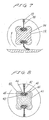
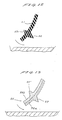
- Fig. 9 shows an agitator 48 having an elongate web 46 including a portion having teeth 47 which is thinner than the remaining portion of the web 46.
- the web 46 is flexibly displaced counterclockwise by contact with a floor surface to be cleaned so as to lie along the floor surface.
- the tooth-free portion of the web 46 is thicker than the portion having the teeth 47, the web 46 is sufficiently resilient as a whole.
- the thinner portion of the web 46 which has the teeth 47 is flexible enough to neatly rub the floor surface while following surface irregularities on the floor surface during relative movement on the floor surface. Dust particles are brushed off the floor surface by the teeth 47 of the web 46.
- the dust particles separated from the floor surface are then effectively drawn into the nozzle housing 7 (Fig. 2) under a vacuum from the vacuum cleaner and by radially recovering action of the web 46 due to both the resiliency thereof and centrifugal forces acting thereon.
- the elongate web 46 When the elongate web 46 is held in contact with the floor surface, it shuts off air streams coming from the front side of the floor nozzle, so that the vacuum from the vacuum cleaner acts intensively and effectively on the floor surface being cleaned.
- the elongate web 46 is in the form of an elongate unitary strip rather than bristles, waste pieces of thread and other filamentary objects are prevented from getting entangled with the web 46.
- Fig. 10 shows another agitator having an elongate web 49 including a proximal portion 50 that is thinner than the remaining portion of the web 49. Even if the elongate web 49 is made of a material of high surface hardness, the thinner proximal portion 50 allows the web 49 to flex along a floor surface to be cleaned for a high dust-collecting capability. Since the material of the web 49 may be high in surface hardness, it may be an elastomeric material which is highly resistant to wear and highly durable.
- the web 49 is extrusion-molded of a thermoplastic elastomer or the like, it is more moldable to achieve a desired tooth shape, can be produced with better yield, and can be pressed to shape with better productivity if the material has a higher hardness.
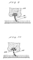
- each elongate web 51 of an agitator 54 is made of a flexible material such as rubber or the like, and has a multiplicity of conical teeth 52, 53 on its opposite surfaces, the teeth 52 being higher than the teeth 53.
- the agitator 54 in a suction chamber 55 is rotated counterclockwise (Fig. 12) to cause the higher teeth 52 to brush up waste threads, hairs, and the like from deep within the carpet tuft.
- the agitator 54 When a carpet having a relative short pile is to be cleaned, the agitator 54 is taken out, turned around, and then put back into the suction chamber 55 to cause the lower teeth 53 to brush up waste threads, hairs, and other filamentary objects from the carpet without damaging the carpet surface.
- the agitator 54 can have a service life which is almost twice the service life of conventional unidirectional agitators.
- Fig. 13 illustrates yet another embodiment in which an elongate web 56 comprises a web member 56a having teeth 57 made of a harder material and a web member 56b having teeth 57′ made of a softer material, the web members 56a, 56b being joined back-to-back to each other.
- the agitator is rotated counterclockwise (Fig. 13) to cause the harder teeth 57 to catch entangled waste threads, hairs, and the like from the carpet tuft.
- the agitator is taken out, turned around, and then put back into the suction chamber to cause the softer teeth 57′ to brush up waste threads, hairs, and other filamentary objects from the carpet without damaging the carpet surface.
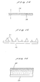
- Fig. 14 shows an elongate web 58 in accordance with a further embodiment of the present invention.
- the web 58 has a plurality of teeth 59 with their height progressively lower toward the center of the web 58 and progressively higher toward the opposite ends of the web 58.
- the teeth 59 which are higher at the opposite ends of the web 58 are effective in separating hairs and waste threads reliably from a floor surface at areas below the opposite ends of the floor nozzle where the vacuum suction is relatively weak. This permits corners of the floor surface being cleaned to be cleaned more effectively by the ends of the floor nozzle.
- Fig. 15 illustrates a still further embodiment of the present invention.
- an elongate web 60 has a plurality of alternately arranged higher and lower conical teeth 61. Since the teeth 61 have alternately different heights, even if the tip ends of the higher teeth 61 are worn and rounded, the lower teeth 61 are still effective to remove thread pieces and hairs from a floor surface being cleaned. Accordingly, a desired dust-collecting capability is maintained over a long period of time.
- teeth 62 on an elongate web 63 are progressively denser toward the distal edge of the web 63 and progressively coarser toward the proximal edge of the web 63. Because the density of the teeth 62 is progressively smaller toward the proximal edge of the web 63, the web 63 is lower in stiffness at the proximal edge and hence can be flexed to rub a floor surface to be cleaned, enabling the denser teeth 62 near the distal edge of the web 63 to catch and collect filamentary dust pieces and hairs with an improved dust-collecting capability.
- filamentary dust pieces such as waste threads and hairs are effectively collected by and prevented from entangled with the agitator on various different floor surfaces in houses, and at the same the floor nozzle can maintain a desired high dust-collecting capability over a long period of time.
- the agitator can also be assembled with ease and is of high quality.
Landscapes
- Engineering & Computer Science (AREA)
- Mechanical Engineering (AREA)
- Nozzles For Electric Vacuum Cleaners (AREA)
Applications Claiming Priority (14)
| Application Number | Priority Date | Filing Date | Title |
|---|---|---|---|
| JP62268663A JPH01110336A (ja) | 1987-10-23 | 1987-10-23 | 電気掃除機用床ノズル |
| JP268663/87 | 1987-10-23 | ||
| JP87476/88 | 1988-04-08 | ||
| JP63087476A JPH01259824A (ja) | 1988-04-08 | 1988-04-08 | 電気掃除機用床ノズル |
| JP89845/88 | 1988-04-12 | ||
| JP63089845A JPH0824639B2 (ja) | 1988-04-12 | 1988-04-12 | 電気掃除機用床ノズル |
| JP63125323A JPH01293827A (ja) | 1988-05-23 | 1988-05-23 | 電気掃除機用床ノズル |
| JP12532488A JPH01293828A (ja) | 1988-05-23 | 1988-05-23 | 電気掃除機用床ノズル |
| JP125326/88 | 1988-05-23 | ||
| JP125325/88 | 1988-05-23 | ||
| JP12532588A JPH01293829A (ja) | 1988-05-23 | 1988-05-23 | 電気掃除機用床ノズル |
| JP125323/88 | 1988-05-23 | ||
| JP125324/88 | 1988-05-23 | ||
| JP12532688A JPH01293830A (ja) | 1988-05-23 | 1988-05-23 | 電気掃除機用床ノズル |
Publications (3)
| Publication Number | Publication Date |
|---|---|
| EP0313403A2 true EP0313403A2 (de) | 1989-04-26 |
| EP0313403A3 EP0313403A3 (en) | 1990-03-28 |
| EP0313403B1 EP0313403B1 (de) | 1993-03-31 |
Family
ID=27565438
Family Applications (1)
| Application Number | Title | Priority Date | Filing Date |
|---|---|---|---|
| EP88309953A Expired - Lifetime EP0313403B1 (de) | 1987-10-23 | 1988-10-21 | Staubsaugermundstück |
Country Status (6)
| Country | Link |
|---|---|
| US (1) | US5029361A (de) |
| EP (1) | EP0313403B1 (de) |
| KR (1) | KR910009949B1 (de) |
| AU (1) | AU588750B2 (de) |
| DE (1) | DE3879867T2 (de) |
| ES (1) | ES2040353T3 (de) |
Cited By (24)
| Publication number | Priority date | Publication date | Assignee | Title |
|---|---|---|---|---|
| EP0338780A2 (de) * | 1988-04-20 | 1989-10-25 | Matsushita Electric Industrial Co., Ltd. | Bodendüse für Staubsauger |
| GB2224197A (en) * | 1988-10-13 | 1990-05-02 | Hoky Kk | Rotary beater |
| GB2225526A (en) * | 1988-12-01 | 1990-06-06 | Hoky Kk | Beater |
| FR2668053A1 (fr) * | 1990-10-17 | 1992-04-24 | Bissell Inc | Rotor et segment de rotor moule d'une seule piece pour appareils de nettoyage des sols et procede de production d'un tel rotor. |
| GB2252901A (en) * | 1991-02-21 | 1992-08-26 | Fedag | Vacuum cleaning tool with turbine driven brush |
| EP0520175A1 (de) * | 1991-06-26 | 1992-12-30 | Wessel-Werk GmbH & Co. Kommanditgesellschaft | Aktive Staubsaugerdüse |
| DE4132869A1 (de) * | 1991-10-03 | 1993-06-09 | Fa. Fedag, Romanshorn, Ch | Saugduese fuer ein saugreinigungsgeraet |
| FR2708841A1 (fr) * | 1993-08-10 | 1995-02-17 | Monti Werkzeuge Gmbh | Brosse manuelle pour le nettoyage en particulier de tapis, de sièges de voitures, de meubles capitonnés ou similaires. |
| FR2748385A1 (fr) * | 1996-05-09 | 1997-11-14 | Fedag | Dispositif de nettoyage a aspiration pour aspirateur |
| WO2001001819A3 (en) * | 1999-07-02 | 2001-04-05 | Oreck Holdings Llc | Agitator for a cleaning machine, such as a floor cleaner, and a method of making the same |
| US6277163B1 (en) | 1999-04-06 | 2001-08-21 | Oreck Holdings Llc | Vacuum cleaner outer bag |
| GB2412571A (en) * | 2004-04-02 | 2005-10-05 | Samsung Kwangju Electronics Co | Reduced width turbine in vacuum cleaner nozzle head |
| EP1712174A2 (de) * | 2005-04-15 | 2006-10-18 | Samsung Gwangju Electronics Co., Ltd. | Turbobürste von Staubsauger |
| US7367085B2 (en) | 2001-11-03 | 2008-05-06 | Dyson Limited | Floor tool |
| WO2010142970A1 (en) * | 2009-06-09 | 2010-12-16 | Dyson Technology Limited | A cleaner head |
| US8402600B2 (en) | 2006-12-13 | 2013-03-26 | Ab Electrolux | Vacuum cleaner nozzle and roller |
| EP2599420A1 (de) | 2011-11-29 | 2013-06-05 | Senur Elektrik Motorlari San. Ve Tic. A.S. | Von einem Luftgebläse gedrehte Staubsaugerdrehbürste mit mehreren Radialkanälen |
| US8782851B2 (en) | 2009-06-09 | 2014-07-22 | Dyson Technology Limited | Cleaner head |
| US8806710B2 (en) | 2009-06-09 | 2014-08-19 | Dyson Technology Limited | Cleaner head |
| WO2019094612A1 (en) * | 2017-11-13 | 2019-05-16 | Tti (Macao Commercial Offshore) Limited | Surface cleaning apparatus |
| EP3479744A4 (de) * | 2016-12-23 | 2020-03-11 | LG Electronics Inc. -1- | Düse für reiniger und staubsauger |
| US10588472B2 (en) | 2017-01-03 | 2020-03-17 | Samsung Electronics Co., Ltd. | Vacuum cleaner |
| CN111343892A (zh) * | 2017-11-13 | 2020-06-26 | 三星电子株式会社 | 清扫机 |
| US20210330161A1 (en) * | 2020-04-24 | 2021-10-28 | Techtronic Cordless Gp | Rotary working element |
Families Citing this family (15)
| Publication number | Priority date | Publication date | Assignee | Title |
|---|---|---|---|---|
| US6226832B1 (en) | 1998-04-23 | 2001-05-08 | Matsushita Home Appliance Corporation Of America | Easy maintenance vacuum cleaner |
| USD431698S (en) * | 1999-04-28 | 2000-10-03 | Matsushita Electric Industrial Co., Ltd. | Rotary brush for electric vacuum cleaner |
| KR100352613B1 (ko) * | 1999-06-11 | 2002-09-12 | 김학열 | 청소기용 브러시 홀더 |
| US6532619B2 (en) | 2000-06-19 | 2003-03-18 | Bissell Homecare, Inc. | Extraction cleaner and agitator therefor |
| US7243393B2 (en) * | 2001-02-06 | 2007-07-17 | The Hoover Company | Agitator drive configuration |
| KR100470559B1 (ko) * | 2002-05-11 | 2005-03-08 | 삼성광주전자 주식회사 | 진공청소기의 흡입구 |
| US7293326B2 (en) | 2004-07-29 | 2007-11-13 | Electrolux Home Care Products, Inc. | Vacuum cleaner alignment bracket |
| AU2006201894B2 (en) | 2005-05-05 | 2010-09-16 | Bissell Inc. | Vacuum accessory tool |
| US20100043160A1 (en) * | 2008-08-20 | 2010-02-25 | United Microelectronics Corp. | Wafer cleaning roller |
| US8261407B2 (en) * | 2009-09-01 | 2012-09-11 | Techtronic Floor Care Technology Limited | Vacuum cleaner accessory tool |
| US9920546B2 (en) * | 2015-05-13 | 2018-03-20 | Zodiac Pool Systems Llc | Components of automatic pool cleaners |
| DE102015114237B4 (de) * | 2015-08-27 | 2021-05-20 | Wessel-Werk Gmbh & Co. Kg | Reinigungsgerät |
| USD955115S1 (en) * | 2018-08-10 | 2022-06-21 | Sharkninja Operating Llc | Brush roll |
| US11832778B2 (en) * | 2020-07-29 | 2023-12-05 | Sharkninja Operating Llc | Nozzle for a surface treatment apparatus and a surface treatment apparatus having the same |
| JP2023545771A (ja) * | 2020-10-08 | 2023-10-31 | シャークニンジャ オペレーティング エルエルシー | 表面処理装置ための撹拌器およびそれを有する表面処理装置 |
Citations (6)
| Publication number | Priority date | Publication date | Assignee | Title |
|---|---|---|---|---|
| GB642819A (en) * | 1948-06-04 | 1950-09-13 | Christopher Collaro | Improvements relating to rotary brushes |
| GB685208A (en) * | 1949-07-01 | 1952-12-31 | James Francis Armstrong Blue | Improvements in and relating to carpet sweepers, vacuum cleaners and textile finishing machines |
| GB1109783A (en) * | 1964-07-16 | 1968-04-18 | Westinghouse Electric Corp | An agitator roll assembly for a suction cleaner |
| EP0084345A2 (de) * | 1982-01-15 | 1983-07-27 | Ludwig Peithmann GmbH & Co. | Bürste für einen Bürstvorsatz eines Staubsaugers |
| DE3526655A1 (de) * | 1984-07-25 | 1986-02-06 | Hukuba Kogyo K.K., Nagareyama, Chiba | Kehrwalze fuer eine kehrmaschine od. dergl. |
| EP0265205A2 (de) * | 1986-10-20 | 1988-04-27 | KABUSHIKI KAISHA HOKY (Trading as HOKY CORPORATION) | Bodenreiniger |
Family Cites Families (15)
| Publication number | Priority date | Publication date | Assignee | Title |
|---|---|---|---|---|
| US1265790A (en) * | 1915-02-17 | 1918-05-14 | James B Kirby | Agitating device for vacuum-cleaner nozzles. |
| US2271551A (en) * | 1938-11-28 | 1942-02-03 | Hoover Co | Suction cleaner |
| US2484235A (en) * | 1945-12-14 | 1949-10-11 | Barker Poultry Equipment Co | Inclined drum poultry picker |
| US2571042A (en) * | 1947-01-08 | 1951-10-09 | Calvin R Kemp | Blade for fowl-plucking apparatus |
| US2607064A (en) * | 1948-09-17 | 1952-08-19 | Owens Brush Company | Hair brushing and massaging implement |
| FR1440453A (fr) * | 1964-07-16 | 1966-05-27 | Westinghouse Electric Corp | Rouleau-brosse |
| US3716889A (en) * | 1970-10-12 | 1973-02-20 | Wallace Leisure Prod Inc | Vacuum cleaner |
| US3872539A (en) * | 1973-02-12 | 1975-03-25 | John S Doyel | Hand-held cleaning device utilizing air flow and broom action |
| US4042995A (en) * | 1976-05-24 | 1977-08-23 | Hyman Varon | Tool for removing animal hair from carpeting |
| US4285737A (en) * | 1978-05-25 | 1981-08-25 | Price John G | Method of cleaning railroad track |
| FR2494982B1 (fr) * | 1980-11-28 | 1986-05-23 | Hoover Ltd | Agitateur pour aspirateur et aspirateur muni d'un tel agitateur |
| US4403372A (en) * | 1982-02-22 | 1983-09-13 | Whirlpool Corporation | Vacuum cleaner brush having string guard means |
| US4480350A (en) * | 1983-04-07 | 1984-11-06 | White Larry F | Sweeper bristle |
| US4586211A (en) * | 1985-01-22 | 1986-05-06 | Phillips Dan D | Tile surface cleaning apparatus |
| DE3877670T2 (de) * | 1987-09-16 | 1993-08-19 | Matsushita Electric Ind Co Ltd | Staubsauger-fussbodenduese. |
-
1988
- 1988-10-21 KR KR1019880013776A patent/KR910009949B1/ko not_active IP Right Cessation
- 1988-10-21 DE DE88309953T patent/DE3879867T2/de not_active Expired - Fee Related
- 1988-10-21 EP EP88309953A patent/EP0313403B1/de not_active Expired - Lifetime
- 1988-10-21 ES ES198888309953T patent/ES2040353T3/es not_active Expired - Lifetime
- 1988-10-21 US US07/260,742 patent/US5029361A/en not_active Expired - Fee Related
- 1988-10-24 AU AU24180/88A patent/AU588750B2/en not_active Ceased
Patent Citations (6)
| Publication number | Priority date | Publication date | Assignee | Title |
|---|---|---|---|---|
| GB642819A (en) * | 1948-06-04 | 1950-09-13 | Christopher Collaro | Improvements relating to rotary brushes |
| GB685208A (en) * | 1949-07-01 | 1952-12-31 | James Francis Armstrong Blue | Improvements in and relating to carpet sweepers, vacuum cleaners and textile finishing machines |
| GB1109783A (en) * | 1964-07-16 | 1968-04-18 | Westinghouse Electric Corp | An agitator roll assembly for a suction cleaner |
| EP0084345A2 (de) * | 1982-01-15 | 1983-07-27 | Ludwig Peithmann GmbH & Co. | Bürste für einen Bürstvorsatz eines Staubsaugers |
| DE3526655A1 (de) * | 1984-07-25 | 1986-02-06 | Hukuba Kogyo K.K., Nagareyama, Chiba | Kehrwalze fuer eine kehrmaschine od. dergl. |
| EP0265205A2 (de) * | 1986-10-20 | 1988-04-27 | KABUSHIKI KAISHA HOKY (Trading as HOKY CORPORATION) | Bodenreiniger |
Cited By (36)
| Publication number | Priority date | Publication date | Assignee | Title |
|---|---|---|---|---|
| EP0338780A2 (de) * | 1988-04-20 | 1989-10-25 | Matsushita Electric Industrial Co., Ltd. | Bodendüse für Staubsauger |
| EP0338780A3 (en) * | 1988-04-20 | 1990-07-04 | Matsushita Electric Ind Co Ltd | Floor nozzle for electric cleaner |
| GB2224197A (en) * | 1988-10-13 | 1990-05-02 | Hoky Kk | Rotary beater |
| GB2225526A (en) * | 1988-12-01 | 1990-06-06 | Hoky Kk | Beater |
| FR2668053A1 (fr) * | 1990-10-17 | 1992-04-24 | Bissell Inc | Rotor et segment de rotor moule d'une seule piece pour appareils de nettoyage des sols et procede de production d'un tel rotor. |
| GB2252901A (en) * | 1991-02-21 | 1992-08-26 | Fedag | Vacuum cleaning tool with turbine driven brush |
| EP0520175A1 (de) * | 1991-06-26 | 1992-12-30 | Wessel-Werk GmbH & Co. Kommanditgesellschaft | Aktive Staubsaugerdüse |
| DE4132869A1 (de) * | 1991-10-03 | 1993-06-09 | Fa. Fedag, Romanshorn, Ch | Saugduese fuer ein saugreinigungsgeraet |
| FR2708841A1 (fr) * | 1993-08-10 | 1995-02-17 | Monti Werkzeuge Gmbh | Brosse manuelle pour le nettoyage en particulier de tapis, de sièges de voitures, de meubles capitonnés ou similaires. |
| FR2748385A1 (fr) * | 1996-05-09 | 1997-11-14 | Fedag | Dispositif de nettoyage a aspiration pour aspirateur |
| US6277163B1 (en) | 1999-04-06 | 2001-08-21 | Oreck Holdings Llc | Vacuum cleaner outer bag |
| WO2001001819A3 (en) * | 1999-07-02 | 2001-04-05 | Oreck Holdings Llc | Agitator for a cleaning machine, such as a floor cleaner, and a method of making the same |
| US6539575B1 (en) | 1999-07-02 | 2003-04-01 | Oreck Holdings, Llc | Agitator for a cleaning machine with material cutting channel |
| US7367085B2 (en) | 2001-11-03 | 2008-05-06 | Dyson Limited | Floor tool |
| AU2004214557B2 (en) * | 2004-04-02 | 2007-05-10 | Samsung Gwangju Electronics Co., Ltd. | Brush assembly and vacuum cleaner including brush assembly |
| GB2412571A (en) * | 2004-04-02 | 2005-10-05 | Samsung Kwangju Electronics Co | Reduced width turbine in vacuum cleaner nozzle head |
| GB2412571B (en) * | 2004-04-02 | 2006-04-12 | Samsung Kwangju Electronics Co | Vacuum cleaner nozzle unit |
| EP1712174A2 (de) * | 2005-04-15 | 2006-10-18 | Samsung Gwangju Electronics Co., Ltd. | Turbobürste von Staubsauger |
| EP1712174A3 (de) * | 2005-04-15 | 2008-01-02 | Samsung Gwangju Electronics Co., Ltd. | Turbobürste von Staubsauger |
| US8402600B2 (en) | 2006-12-13 | 2013-03-26 | Ab Electrolux | Vacuum cleaner nozzle and roller |
| US8782851B2 (en) | 2009-06-09 | 2014-07-22 | Dyson Technology Limited | Cleaner head |
| US8316503B2 (en) | 2009-06-09 | 2012-11-27 | Dyson Technology Limited | Cleaner head |
| WO2010142970A1 (en) * | 2009-06-09 | 2010-12-16 | Dyson Technology Limited | A cleaner head |
| US8806710B2 (en) | 2009-06-09 | 2014-08-19 | Dyson Technology Limited | Cleaner head |
| EP2599420A1 (de) | 2011-11-29 | 2013-06-05 | Senur Elektrik Motorlari San. Ve Tic. A.S. | Von einem Luftgebläse gedrehte Staubsaugerdrehbürste mit mehreren Radialkanälen |
| WO2013079515A1 (en) | 2011-11-29 | 2013-06-06 | Senur Elektrik Motorlari San. Ve Tic. A.S. | A vacuum cleaner rotary brush having a plurality of radial channels being rotated by an air fan |
| EP3479744A4 (de) * | 2016-12-23 | 2020-03-11 | LG Electronics Inc. -1- | Düse für reiniger und staubsauger |
| US11540685B2 (en) | 2016-12-23 | 2023-01-03 | Lg Electronics Inc. | Nozzle for cleaner, and vacuum cleaner |
| US10588472B2 (en) | 2017-01-03 | 2020-03-17 | Samsung Electronics Co., Ltd. | Vacuum cleaner |
| WO2019094612A1 (en) * | 2017-11-13 | 2019-05-16 | Tti (Macao Commercial Offshore) Limited | Surface cleaning apparatus |
| CN111343892A (zh) * | 2017-11-13 | 2020-06-26 | 三星电子株式会社 | 清扫机 |
| EP3689211A4 (de) * | 2017-11-13 | 2020-12-23 | Samsung Electronics Co., Ltd. | Reiniger |
| CN111343892B (zh) * | 2017-11-13 | 2022-09-13 | 三星电子株式会社 | 清扫机 |
| US11517159B2 (en) | 2017-11-13 | 2022-12-06 | Samsung Electronics Co., Ltd. | Cleaner |
| US20210330161A1 (en) * | 2020-04-24 | 2021-10-28 | Techtronic Cordless Gp | Rotary working element |
| WO2021217033A1 (en) * | 2020-04-24 | 2021-10-28 | Techtronic Cordless Gp | Rotary working element |
Also Published As
| Publication number | Publication date |
|---|---|
| DE3879867T2 (de) | 1993-10-14 |
| EP0313403A3 (en) | 1990-03-28 |
| US5029361A (en) | 1991-07-09 |
| KR910009949B1 (ko) | 1991-12-07 |
| AU2418088A (en) | 1989-04-27 |
| ES2040353T3 (es) | 1993-10-16 |
| EP0313403B1 (de) | 1993-03-31 |
| DE3879867D1 (de) | 1993-05-06 |
| KR890006196A (ko) | 1989-06-12 |
| AU588750B2 (en) | 1989-09-21 |
Similar Documents
| Publication | Publication Date | Title |
|---|---|---|
| EP0313403B1 (de) | Staubsaugermundstück | |
| US4372004A (en) | Wide-sweep carpet cleaner bristle strip and brush roll | |
| US11395569B2 (en) | Brushroll for vacuum cleaner | |
| US11759069B2 (en) | Agitator for a surface treatment apparatus and a surface treatment apparatus having the same | |
| JP3183445B2 (ja) | 電気掃除機の吸込口体およびその回転清掃体 | |
| JPH0815472B2 (ja) | 電気掃除機の吸込口体 | |
| KR100382237B1 (ko) | 전기 청소기용 흡입구 | |
| CA3087466C (en) | Brushroll for vacuum cleaner | |
| CA2101455C (en) | Vacuum sweeper drive belt | |
| JPH06105771A (ja) | 電気掃除機の吸口 | |
| JPH0549568A (ja) | 電気掃除機用吸込具 | |
| US20220095864A1 (en) | Agitator for a surface treatment apparatus and a surface treatment apparatus having the same | |
| US11992172B2 (en) | Agitator for a surface treatment apparatus and a surface treatment apparatus having the same | |
| US20240172908A1 (en) | Agitator for a surface treatment apparatus and a surface treatment apparatus having the same | |
| US20240099527A9 (en) | Agitator for a surface treatment apparatus and a surface treatment apparatus having the same | |
| JP2023545771A (ja) | 表面処理装置ための撹拌器およびそれを有する表面処理装置 | |
| KR930000969Y1 (ko) | 마루용 흡입구 | |
| JPH04152923A (ja) | 電気掃除機の床ノズル | |
| GB2620119A (en) | Vacuum cleaner head having agitator element and rib | |
| JPH0549565A (ja) | 電気掃除機用吸込具 | |
| JPH04314411A (ja) | 電気掃除機の吸込口体 | |
| JPH0219123A (ja) | 電気掃除機用床ノズル | |
| JPH07327881A (ja) | 電気掃除機の床用吸込具 | |
| JPH0433628A (ja) | 電気掃除機用床ノズル | |
| JP2000126099A (ja) | 床用吸込具 |
Legal Events
| Date | Code | Title | Description |
|---|---|---|---|
| PUAI | Public reference made under article 153(3) epc to a published international application that has entered the european phase |
Free format text: ORIGINAL CODE: 0009012 |
|
| 17P | Request for examination filed |
Effective date: 19881102 |
|
| AK | Designated contracting states |
Kind code of ref document: A2 Designated state(s): DE ES GB |
|
| PUAL | Search report despatched |
Free format text: ORIGINAL CODE: 0009013 |
|
| AK | Designated contracting states |
Kind code of ref document: A3 Designated state(s): DE ES GB |
|
| 17Q | First examination report despatched |
Effective date: 19910715 |
|
| GRAA | (expected) grant |
Free format text: ORIGINAL CODE: 0009210 |
|
| AK | Designated contracting states |
Kind code of ref document: B1 Designated state(s): DE ES GB |
|
| REF | Corresponds to: |
Ref document number: 3879867 Country of ref document: DE Date of ref document: 19930506 |
|
| PGFP | Annual fee paid to national office [announced via postgrant information from national office to epo] |
Ref country code: GB Payment date: 19931012 Year of fee payment: 6 |
|
| REG | Reference to a national code |
Ref country code: ES Ref legal event code: FG2A Ref document number: 2040353 Country of ref document: ES Kind code of ref document: T3 |
|
| PGFP | Annual fee paid to national office [announced via postgrant information from national office to epo] |
Ref country code: DE Payment date: 19931021 Year of fee payment: 6 |
|
| PGFP | Annual fee paid to national office [announced via postgrant information from national office to epo] |
Ref country code: ES Payment date: 19931029 Year of fee payment: 6 |
|
| PLBE | No opposition filed within time limit |
Free format text: ORIGINAL CODE: 0009261 |
|
| STAA | Information on the status of an ep patent application or granted ep patent |
Free format text: STATUS: NO OPPOSITION FILED WITHIN TIME LIMIT |
|
| 26N | No opposition filed | ||
| PG25 | Lapsed in a contracting state [announced via postgrant information from national office to epo] |
Ref country code: GB Effective date: 19941021 |
|
| PG25 | Lapsed in a contracting state [announced via postgrant information from national office to epo] |
Ref country code: ES Free format text: LAPSE BECAUSE OF THE APPLICANT RENOUNCES Effective date: 19941022 |
|
| GBPC | Gb: european patent ceased through non-payment of renewal fee |
Effective date: 19941021 |
|
| PG25 | Lapsed in a contracting state [announced via postgrant information from national office to epo] |
Ref country code: DE Effective date: 19950701 |
|
| REG | Reference to a national code |
Ref country code: ES Ref legal event code: FD2A Effective date: 20001102 |