EP0312827A2 - Dispositif de nettoyage d'un cylindre de transfert d'une machine d'impression rotative - Google Patents
Dispositif de nettoyage d'un cylindre de transfert d'une machine d'impression rotative Download PDFInfo
- Publication number
- EP0312827A2 EP0312827A2 EP88116382A EP88116382A EP0312827A2 EP 0312827 A2 EP0312827 A2 EP 0312827A2 EP 88116382 A EP88116382 A EP 88116382A EP 88116382 A EP88116382 A EP 88116382A EP 0312827 A2 EP0312827 A2 EP 0312827A2
- Authority
- EP
- European Patent Office
- Prior art keywords
- cylinder
- brushes
- cleaned
- cleaning
- cleaning device
- Prior art date
- Legal status (The legal status is an assumption and is not a legal conclusion. Google has not performed a legal analysis and makes no representation as to the accuracy of the status listed.)
- Granted
Links
- 238000004140 cleaning Methods 0.000 title claims abstract description 17
- 230000001681 protective effect Effects 0.000 claims abstract description 14
- 239000012459 cleaning agent Substances 0.000 claims description 5
- 230000002441 reversible effect Effects 0.000 claims 1
- 239000000428 dust Substances 0.000 abstract description 4
- 238000010276 construction Methods 0.000 description 1
- 238000011161 development Methods 0.000 description 1
- 230000018109 developmental process Effects 0.000 description 1
Images

Classifications
-
- B—PERFORMING OPERATIONS; TRANSPORTING
- B41—PRINTING; LINING MACHINES; TYPEWRITERS; STAMPS
- B41F—PRINTING MACHINES OR PRESSES
- B41F35/00—Cleaning arrangements or devices
- B41F35/06—Cleaning arrangements or devices for offset cylinders
-
- B—PERFORMING OPERATIONS; TRANSPORTING
- B41—PRINTING; LINING MACHINES; TYPEWRITERS; STAMPS
- B41P—INDEXING SCHEME RELATING TO PRINTING, LINING MACHINES, TYPEWRITERS, AND TO STAMPS
- B41P2235/00—Cleaning
- B41P2235/10—Cleaning characterised by the methods or devices
- B41P2235/20—Wiping devices
- B41P2235/23—Brushes
Definitions
- the invention relates to a device for cleaning a transfer cylinder of a rotary printing press during operation, with cleaning agents which can be arranged on the cylinder to be cleaned and which are arranged approximately parallel to the axis.
- a device for cleaning a transfer cylinder of a printing press is known, by means of which dust and lint can be removed from a transfer cylinder during operation. Brushes are pressed periodically against the transfer cylinder, which is preferably a rubber blanket cylinder, dust and lint being swept away by the latter and fed to a so-called lint catcher.
- This device is arranged on the periphery of the transfer cylinder and fastened on both sides to the printing unit side walls. It can be seen as a nuisance that this device is arranged on the periphery of the transfer cylinder, since this affects work on the machine.
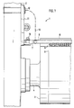
- the protection and cleaning device 1 according to the invention is arranged on a blanket cylinder 3 mounted in a side wall 2 or can be adjusted to it.
- the blanket cylinder 3 can be supported on both sides, as indicated in FIG. 1, by means of pins 4.
- the design of the protection and cleaning device 1 according to the invention can be carried out on the left side of the blanket cylinder 3 in the same way.
- a suction pipe 8 is positioned on or in the crossmember 7, with which the dust, lint and dirt are sucked off from the brushes 9 arranged in the axial direction of the cylinder to be cleaned, or from the surroundings thereof, by means of the brushes 9 from the Printing unit cylinder 3, for example a cylinder carrying a blanket 5, is removed.
- the suction pipe 8 is connected to a flexible, schematically indicated hose 10, which can lead to a suction device (not shown) via the printing unit side wall.
- a pivotable lever 11 is preferably provided on both ends at the ends, which is rotatably supported on brackets 12 on one side and one end of the cross member 7 is attached to the other side of each.
- Another blanket cylinder 13 is employed, which, depending on the construction of the machine, is an impression cylinder, another blanket cylinder or, as in the present case, a plate cylinder 13.
- a further blanket cylinder 14 is attached to the blanket cylinder 3, so that a printing medium, for example a paper web, carried out between the cylinders 3, 14 can be printed on both sides. It goes without saying that such protective and cleaning devices can also be attached to the further blanket cylinder 14.
- the protection and cleaning device according to the invention is therefore preferably double, ie provided at an inlet gap 19, 20, as indicated at 1 and 17.
- the protective and cleaning device 1, 17 described above is therefore arranged in the region of the approximately triangular inlet gap 19 and / or 20.
- the protection and cleaning device 1 or 17 does not interfere with handling on the printing press.
- protective strips are also required in the area of the inlet gaps for safety reasons, a significant advantage of the invention results from the fact that the means required for cleaning the cylinders are arranged in or behind the protective strip, where they do not interfere paractically and the means required for mounting and adjustment, for example the levers 11, are also only required once.
- the setting or adjustment of the protective strip 6 and the brushes 9 is indicated at 18.
- 9 can also be used instead of the brushes Cleaning elements are used, although it is advantageous, but not absolutely necessary, to work with a suction device.
- the protective strips 6 can be produced in a simple manner from angles or semicircular profiles.
- the pivoting of the levers 11 can be done manually or, preferably, with known electrical or mechanical devices, which also applies to the adjusting and parking device 18.
Landscapes
- Inking, Control Or Cleaning Of Printing Machines (AREA)
Applications Claiming Priority (2)
| Application Number | Priority Date | Filing Date | Title |
|---|---|---|---|
| DE19873735302 DE3735302A1 (de) | 1987-10-17 | 1987-10-17 | Vorrichtung zum reinigen eines uebertragungszylinders einer rotationsdruckmaschine |
| DE3735302 | 1987-10-17 |
Publications (3)
| Publication Number | Publication Date |
|---|---|
| EP0312827A2 true EP0312827A2 (fr) | 1989-04-26 |
| EP0312827A3 EP0312827A3 (en) | 1990-09-26 |
| EP0312827B1 EP0312827B1 (fr) | 1993-12-15 |
Family
ID=6338614
Family Applications (1)
| Application Number | Title | Priority Date | Filing Date |
|---|---|---|---|
| EP88116382A Expired - Lifetime EP0312827B1 (fr) | 1987-10-17 | 1988-10-04 | Dispositif de nettoyage d'un cylindre de transfert d'une machine d'impression rotative |
Country Status (5)
| Country | Link |
|---|---|
| US (1) | US4905596A (fr) |
| EP (1) | EP0312827B1 (fr) |
| JP (1) | JP2812687B2 (fr) |
| CA (1) | CA1297238C (fr) |
| DE (2) | DE3735302A1 (fr) |
Cited By (3)
| Publication number | Priority date | Publication date | Assignee | Title |
|---|---|---|---|---|
| EP0369565A2 (fr) * | 1988-11-17 | 1990-05-23 | Baldwin Technology Corporation | Dispositif de nettoyage du blanchet dans une presse |
| US5265537A (en) * | 1988-11-17 | 1993-11-30 | Baldwin Technology Corporation | Printing press blanket cleaner |
| US5322015A (en) * | 1988-02-08 | 1994-06-21 | Baldwin Technology Corporation | Rotating brush cleaner system |
Families Citing this family (14)
| Publication number | Priority date | Publication date | Assignee | Title |
|---|---|---|---|---|
| US5148746A (en) * | 1988-08-19 | 1992-09-22 | Presstek, Inc. | Print-head and plate-cleaning assembly |
| DE3938478A1 (de) * | 1989-11-20 | 1991-05-23 | Koenig & Bauer Ag | Vorrichtung zum verhindern von maschinenschaeden |
| US5259313A (en) * | 1991-12-20 | 1993-11-09 | Heidelberg Harris Gmbh | Method and apparatus for cleaning an inking mechanism and/or a printing mechanism in printing units of rotary printing machines |
| DE4221132C2 (de) * | 1992-06-27 | 1995-01-19 | Heidelberger Druckmasch Ag | Vorrichtung zur Absicherung der Gefahrenstellen eines Druckwerkes |
| DE4417054B4 (de) * | 1994-05-14 | 2007-01-11 | Heidelberger Druckmaschinen Ag | Andrückvorrichtung im Druckwerk einer Druckmaschine |
| US5842417A (en) * | 1995-04-25 | 1998-12-01 | Heidelberger Druckmaschinen Ag | Apparatus for preventing condensation in machines processing a web of material |
| DE19526574C1 (de) * | 1995-07-20 | 1996-10-17 | Roland Man Druckmasch | Verfahren und Vorrichtung zum Waschen eines Formzylinders und einer zugeordneten Auftragwalze in einer Druckmaschine |
| US5755158A (en) * | 1996-08-28 | 1998-05-26 | Presstek, Inc. | Alternately engageable, dual-stage cleaning system for lithographic printing plates |
| US5870954A (en) * | 1998-01-22 | 1999-02-16 | Presstek, Inc. | Retractable cleaning system for lithographic printing plates |
| DE19860859A1 (de) * | 1998-12-31 | 2000-07-06 | Koenig & Bauer Ag | Vorrichtung zum Reinigen einer Walze |
| US6158343A (en) * | 1999-05-28 | 2000-12-12 | M&R Printing Equipment, Inc. | Contaminant remover for printing machine |
| US6588698B2 (en) * | 2001-11-26 | 2003-07-08 | Gl&V Management Hungary Kft | Winding machine including a finger sensor adjacent the nip formed between a support drum and a web reel |
| SE0401185L (sv) * | 2004-05-07 | 2005-11-08 | Baldwin Jimek Ab | Ett system för att rengöra en dukcylinder och en metod för att rengöra en dukcylinder |
| SE0401186L (sv) * | 2004-05-07 | 2005-08-23 | Baldwin Jimek Ab | Borstarrangemang för att rengöra en duk på en roterbar dukcylinder |
Citations (3)
| Publication number | Priority date | Publication date | Assignee | Title |
|---|---|---|---|---|
| US2961953A (en) * | 1958-05-27 | 1960-11-29 | Carl Allers Ets As | Printing machines |
| DE3601539A1 (de) * | 1985-01-22 | 1986-07-24 | Gary C. St. Louis Mo. Glanzner | Vorrichtung zum reinigen des uebertragzylinders einer druckerpresse |
| DE3610697C1 (de) * | 1986-03-29 | 1987-02-26 | Roland Man Druckmasch | Schutzleiste an gegenlaeufigen Zylindern von Rotationsdruckmaschinen |
Family Cites Families (14)
| Publication number | Priority date | Publication date | Assignee | Title |
|---|---|---|---|---|
| US1196438A (en) * | 1914-09-29 | 1916-08-29 | Charles S Britton | Suction-nozzle attachment for printing-presses. |
| US1562010A (en) * | 1922-03-28 | 1925-11-17 | R Hoe And Co Inc | Guard for printing cylinders and the like |
| GB392326A (en) * | 1932-03-16 | 1933-05-18 | Coop Wholesale | Improvements in or relating to offset litho and letter-press printing machines |
| US2086227A (en) * | 1935-06-07 | 1937-07-06 | Hoe & Co R | Printing machine |
| US2704026A (en) * | 1953-08-24 | 1955-03-15 | Edmund A Rogge | Doctor blade and mounting for rotogravure printing machines |
| GB747444A (en) * | 1953-10-19 | 1956-04-04 | Goss Printing Press Co Ltd | Improvements in or relating to delivery mechanisms for printing presses |
| FR1141751A (fr) * | 1955-05-17 | 1957-09-09 | Vernicolor A G | Machine à imprimer offset pour impression rotative et feuille à feuille avec dispositif de nettoyage des cylindres |
| US3508711A (en) * | 1967-12-29 | 1970-04-28 | Ryco Graphic Mfg | Fluid dispensing system |
| US3735702A (en) * | 1971-05-12 | 1973-05-29 | Oxy Dry Sprayer Corp | Apparatus and method for cleaning rotating cylindrical surfaces |
| US4162652A (en) * | 1978-05-25 | 1979-07-31 | Roland Offsetmaschinenfabrik Faber & Schleicher Ag | Device for cleaning cylinder bearers on printing presses |
| JPS55871A (en) * | 1978-06-20 | 1980-01-07 | Matsushita Electric Ind Co Ltd | Consumed gas quantity indicator |
| JPS5956037U (ja) * | 1982-10-06 | 1984-04-12 | 小森印刷機械株式会社 | 印刷機の安全装置 |
| JPS59192334U (ja) * | 1983-06-08 | 1984-12-20 | 大日本印刷株式会社 | オフセツト輪転機のユニツト部における安全ステ− |
| DE3441963C2 (de) * | 1984-11-16 | 1987-01-22 | M.A.N.- Roland Druckmaschinen AG, 6050 Offenbach | Sicherheitseinrichtung an Bogenrotationsdruckmaschinen |
-
1987
- 1987-10-17 DE DE19873735302 patent/DE3735302A1/de active Granted
-
1988
- 1988-09-30 US US07/252,173 patent/US4905596A/en not_active Expired - Fee Related
- 1988-10-04 EP EP88116382A patent/EP0312827B1/fr not_active Expired - Lifetime
- 1988-10-04 DE DE88116382T patent/DE3886339D1/de not_active Expired - Fee Related
- 1988-10-13 CA CA000580057A patent/CA1297238C/fr not_active Expired - Lifetime
- 1988-10-17 JP JP63259614A patent/JP2812687B2/ja not_active Expired - Lifetime
Patent Citations (3)
| Publication number | Priority date | Publication date | Assignee | Title |
|---|---|---|---|---|
| US2961953A (en) * | 1958-05-27 | 1960-11-29 | Carl Allers Ets As | Printing machines |
| DE3601539A1 (de) * | 1985-01-22 | 1986-07-24 | Gary C. St. Louis Mo. Glanzner | Vorrichtung zum reinigen des uebertragzylinders einer druckerpresse |
| DE3610697C1 (de) * | 1986-03-29 | 1987-02-26 | Roland Man Druckmasch | Schutzleiste an gegenlaeufigen Zylindern von Rotationsdruckmaschinen |
Cited By (4)
| Publication number | Priority date | Publication date | Assignee | Title |
|---|---|---|---|---|
| US5322015A (en) * | 1988-02-08 | 1994-06-21 | Baldwin Technology Corporation | Rotating brush cleaner system |
| EP0369565A2 (fr) * | 1988-11-17 | 1990-05-23 | Baldwin Technology Corporation | Dispositif de nettoyage du blanchet dans une presse |
| EP0369565A3 (en) * | 1988-11-17 | 1990-10-10 | Baldwin Technology Corporation | Printing press blanket cleaner |
| US5265537A (en) * | 1988-11-17 | 1993-11-30 | Baldwin Technology Corporation | Printing press blanket cleaner |
Also Published As
| Publication number | Publication date |
|---|---|
| US4905596A (en) | 1990-03-06 |
| EP0312827A3 (en) | 1990-09-26 |
| DE3735302C2 (fr) | 1991-10-31 |
| JP2812687B2 (ja) | 1998-10-22 |
| DE3886339D1 (de) | 1994-01-27 |
| CA1297238C (fr) | 1992-03-17 |
| JPH01128835A (ja) | 1989-05-22 |
| DE3735302A1 (de) | 1989-04-27 |
| EP0312827B1 (fr) | 1993-12-15 |
Similar Documents
| Publication | Publication Date | Title |
|---|---|---|
| EP0312827B1 (fr) | Dispositif de nettoyage d'un cylindre de transfert d'une machine d'impression rotative | |
| DE69407435T2 (de) | Vorrichtung und verfahren zum reinigen der oberfläche einer walze | |
| EP0712725B2 (fr) | Rouleau de pression pour presser un cliché flexible contre le cylindre de forme | |
| DE2815388C3 (de) | Vorrichtung zum Waschen von Zylindern an Druckmaschinen, insbesondere Offsetdruckmaschinen | |
| DE3789975T2 (de) | Reinigungssystem für eine Druckmaschine. | |
| DE69118587T2 (de) | Waschvorrichtung mit rotierender Bürste | |
| DE3241124A1 (de) | Farbabteilkeil in einem farbkasten einer rotationsdruckmaschine | |
| DE4215355A1 (de) | Waschvorrichtung für Zylinder in Druckmaschinen, insbesondere Bogenoffsetdruckmaschinen | |
| DE69405824T2 (de) | Farbwerk für Druckmaschinen | |
| EP0606581B1 (fr) | Dispositif de nettoyage automatique des cylindres de blanchet d'une rotative à rouleaux | |
| EP0704302A1 (fr) | Dispositif pour alimenter une plaque d'impression vers le cylindre porte-plaque d'une machine à imprimer | |
| EP0835837B1 (fr) | Dispositifs pour éviter des incidents de production dans des dispositifs de pliage | |
| DE3121244C2 (de) | Tunnelvortriebsmaschine | |
| CH661898A5 (de) | Rollenoffset-rotationsdruckmaschine. | |
| CH659620A5 (de) | Druckmaschine, insbesondere zum bedrucken von hohlen werkstuecken. | |
| DE3223653A1 (de) | Bogenausleger einer rotationssiebdruckmaschine | |
| DD274003A1 (de) | Rakeleinrichtung fuer offsetdruckmaschinen | |
| DD259600A1 (de) | Einrichtung zum waschen eines zylinders einer druckmaschine | |
| EP1256449B1 (fr) | Imprimante avec un cylindre de plaque et avec une barre d'insertion | |
| EP0544126A2 (fr) | Machine d'impression | |
| DE19750660C1 (de) | Siebdruckmaschine | |
| DE2238039A1 (de) | Vorrichtung zum entfernen von fremdpartikeln von einer lithographischen druckpresse | |
| DE29819374U1 (de) | Reinigungsvorrichtung zum Reinigen der Mantelfläche eines Zylinders in einer Druckmaschine | |
| DE3835266A1 (de) | Einrichtung zur abschmierfreien bogenfuehrung | |
| DE29511688U1 (de) | Druckmaschinenreinigungsvorrichtung, insbesondere zum Reinigen der Druckplattenzylinder einer Bogendruckmaschine |
Legal Events
| Date | Code | Title | Description |
|---|---|---|---|
| PUAI | Public reference made under article 153(3) epc to a published international application that has entered the european phase |
Free format text: ORIGINAL CODE: 0009012 |
|
| AK | Designated contracting states |
Kind code of ref document: A2 Designated state(s): CH DE FR GB IT LI SE |
|
| PUAL | Search report despatched |
Free format text: ORIGINAL CODE: 0009013 |
|
| AK | Designated contracting states |
Kind code of ref document: A3 Designated state(s): CH DE FR GB IT LI SE |
|
| 17P | Request for examination filed |
Effective date: 19900911 |
|
| 17Q | First examination report despatched |
Effective date: 19920617 |
|
| ITF | It: translation for a ep patent filed | ||
| GRAA | (expected) grant |
Free format text: ORIGINAL CODE: 0009210 |
|
| AK | Designated contracting states |
Kind code of ref document: B1 Designated state(s): CH DE FR GB IT LI SE |
|
| GBT | Gb: translation of ep patent filed (gb section 77(6)(a)/1977) |
Effective date: 19931220 |
|
| REF | Corresponds to: |
Ref document number: 3886339 Country of ref document: DE Date of ref document: 19940127 |
|
| ET | Fr: translation filed | ||
| PLBE | No opposition filed within time limit |
Free format text: ORIGINAL CODE: 0009261 |
|
| STAA | Information on the status of an ep patent application or granted ep patent |
Free format text: STATUS: NO OPPOSITION FILED WITHIN TIME LIMIT |
|
| 26N | No opposition filed | ||
| EAL | Se: european patent in force in sweden |
Ref document number: 88116382.8 |
|
| PGFP | Annual fee paid to national office [announced via postgrant information from national office to epo] |
Ref country code: GB Payment date: 19980914 Year of fee payment: 11 |
|
| PGFP | Annual fee paid to national office [announced via postgrant information from national office to epo] |
Ref country code: FR Payment date: 19980916 Year of fee payment: 11 |
|
| PGFP | Annual fee paid to national office [announced via postgrant information from national office to epo] |
Ref country code: SE Payment date: 19980918 Year of fee payment: 11 |
|
| PGFP | Annual fee paid to national office [announced via postgrant information from national office to epo] |
Ref country code: DE Payment date: 19980922 Year of fee payment: 11 |
|
| PGFP | Annual fee paid to national office [announced via postgrant information from national office to epo] |
Ref country code: CH Payment date: 19980929 Year of fee payment: 11 |
|
| PG25 | Lapsed in a contracting state [announced via postgrant information from national office to epo] |
Ref country code: GB Free format text: LAPSE BECAUSE OF NON-PAYMENT OF DUE FEES Effective date: 19991004 |
|
| PG25 | Lapsed in a contracting state [announced via postgrant information from national office to epo] |
Ref country code: SE Free format text: THE PATENT HAS BEEN ANNULLED BY A DECISION OF A NATIONAL AUTHORITY Effective date: 19991030 |
|
| PG25 | Lapsed in a contracting state [announced via postgrant information from national office to epo] |
Ref country code: LI Free format text: LAPSE BECAUSE OF NON-PAYMENT OF DUE FEES Effective date: 19991031 Ref country code: CH Free format text: LAPSE BECAUSE OF NON-PAYMENT OF DUE FEES Effective date: 19991031 |
|
| GBPC | Gb: european patent ceased through non-payment of renewal fee |
Effective date: 19991004 |
|
| REG | Reference to a national code |
Ref country code: CH Ref legal event code: PL |
|
| EUG | Se: european patent has lapsed |
Ref document number: 88116382.8 |
|
| PG25 | Lapsed in a contracting state [announced via postgrant information from national office to epo] |
Ref country code: FR Free format text: LAPSE BECAUSE OF NON-PAYMENT OF DUE FEES Effective date: 20000630 |
|
| PG25 | Lapsed in a contracting state [announced via postgrant information from national office to epo] |
Ref country code: DE Free format text: LAPSE BECAUSE OF NON-PAYMENT OF DUE FEES Effective date: 20000801 |
|
| REG | Reference to a national code |
Ref country code: FR Ref legal event code: ST |
|
| PG25 | Lapsed in a contracting state [announced via postgrant information from national office to epo] |
Ref country code: IT Free format text: LAPSE BECAUSE OF NON-PAYMENT OF DUE FEES;WARNING: LAPSES OF ITALIAN PATENTS WITH EFFECTIVE DATE BEFORE 2007 MAY HAVE OCCURRED AT ANY TIME BEFORE 2007. THE CORRECT EFFECTIVE DATE MAY BE DIFFERENT FROM THE ONE RECORDED. Effective date: 20051004 |